
Related Manuals for NTI ENVIROMUX-MINI-LXO


Summary of Contents for NTI ENVIROMUX-MINI-LXO
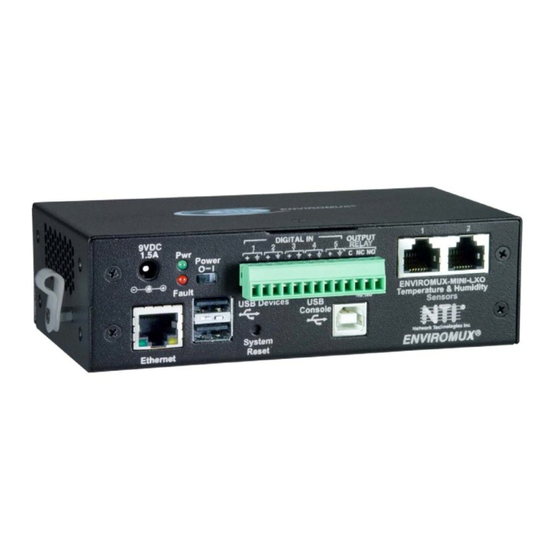
- Page 1 ® ENVIROMUX Series ENVIROMUX-MINI-LXO Mini Server Environment Monitoring System Installation and Operation Manual Front View of ENVIROMUX-MINI-LXO MAN143 Rev Date 12/19/13...
- Page 2 TRADEMARK ENVIROMUX is a registered trademark of Network Technologies Inc in the U.S. and other countries. COPYRIGHT Copyright © 2009, 2013 by Network Technologies Inc. All rights reserved. No part of this publication may be reproduced, stored in a retrieval system, or transmitted, in any form or by any means, electronic, mechanical, photocopying, recording, or otherwise, without the prior written consent of Network Technologies Inc, 1275 Danner Drive, Aurora, Ohio 44202.
-
Page 3: Table Of Contents
TABLE OF CONTENTS Introduction..................................1 Supported Web Browsers ............................... 2 Materials ..................................2 Connectors and LEDs ..............................3 Installation ..................................4 Connect Sensors ................................. 4 Output Relay................................6 Ethernet Connection ..............................6 USB Console Port................................ 7 Installing Drivers ............................... 7 Using the USB Console Port .......................... - Page 4 Figure 4- Portion of Water Sensor configuration page ........................5 Figure 5- Output Relay Application Examples ........................... 6 Figure 6- Connect ENVIROMUX-MINI-LXO to the Ethernet ......................6 Figure 7- Connect terminal to USB Console port..........................7 Figure 8- COM port assigned to ENVIROMUX ..........................12 Figure 9- Configure COM port in HyperTerminal ..........................
- Page 5 Figure 16- Summary page and the Monitoring menu........................20 Figure 17- Status page for a temperature sensor ..........................21 Figure 18- Sensor Configuration page ............................. 22 Figure 19- Sensor Configuration- exploded view of additional settings ................... 23 Figure 20- Chart to setup alert notification ............................25 Figure 21- Sensor Configuration for Digital Inputs ...........................
- Page 6 Figure 67- Text Menu-View IP Devices............................64 Figure 68- Text Menu- View Output Relay Status..........................64 Figure 69- Text Menu-Configure Sensors list ..........................65 Figure 70- Text Menu-Configuration Menu for Sensor........................65 Figure 71- Text Menu-Sensor Settings ............................66 Figure 72- Text Menu-Non-Critical and Critical Alert Settings......................67 Figure 73- Text Menu-Sensor Data Logging............................
- Page 7 Figure 118- Text Menu-User accessible status menus ........................96 Figure 119- Text Menu-User Accessible Settings..........................97 Figure 120- Text Menu-User Account Settings ..........................97 Figure 121- Text Menu-User Contact Settings..........................98 Figure 122- Text Menu-User Activity Schedule..........................99 Figure 123- Text Menu-User SNMP Settings........................... 99 Figure 124- Location of Reset buttons ............................
-
Page 8: Introduction
Alert methods include email, SMS, SNMP traps (MIBs), web-page alerts, and a visual indicator (red LED). The ENVIROMUX-MINI-LXO will monitor temperature, humidity, and detect the presence of water on a flat surface (such as the floor). The unit also has four sets of terminal block pairs for the connection of contact-closure sensors. -
Page 9: Supported Web Browsers
CAT5/5e/6 unshielded twisted-pair cable(s) terminated with RJ45 connectors wired straight thru- pin 1 to pin 1, etc. for Ethernet connection Contact your nearest NTI distributor or NTI directly for all of your cable needs at 800-RGB-TECH (800-742-8324) in US & Canada or 330-562-7070 (Worldwide) or at our website at http://www.networktechinc.com... -
Page 10: Connectors And Leds
NTI Mini Server Environment Monitoring System CONNECTORS AND LEDS LABEL CONNECTOR/LED DESCRIPTION Green LED green — indicates device is powered Fault Red LED red — illuminates if a sensor goes out of range of a configurable threshold USB Console USB Type B female connector... -
Page 11: Installation
NTI Mini Server Environment Monitoring System INSTALLATION Connect Sensors Connect the desired sensors (sold separately) to the available ports on the ENVIROMUX. Plug the RJ45 connectors to either of the two RJ45 ports marked "TEMPERATURE/HUMIDITY". Mount the sensors according to their individual operating characteristics. -
Page 12: Figure 3- Secure Liquid Detection Sensor With Tape
NTI Mini Server Environment Monitoring System Optionally, connect the two-wire cable from a liquid detection sensor (ENVIROMUX-LD shown below- sold separately) to a set of “DIGITAL IN” contacts. The twisted orange sensing cable should be placed flat on the surface (usually the floor) where liquid detection is desired. If tape is required to hold the sensor in place, be sure to only apply tape to the ends, exposing as much of the sensor as possible. -
Page 13: Output Relay
Connect a CAT5 patch cable (RJ45 connectors on each end wired pin 1 to pin 1, pin 2 to pin 2 etc) from the local Ethernet network connection to the connector on the ENVIROMUX marked "Ethernet". Figure 6- Connect ENVIROMUX-MINI-LXO to the Ethernet Note: A direct Ethernet connection can be made with a PC using a crossover cable. For the pinout of this cable, see... -
Page 14: Usb Console Port
NTI Mini Server Environment Monitoring System USB Console Port Your ENVIROMUX includes a USB Type B connector labeled “USB Console”. If you connect a USB cable between the ENVIROMUX and your PC you will be able to control your ENVIROMUX serially from a terminal console using this connection. - Page 15 NTI Mini Server Environment Monitoring System Windows XP-32 bit Installation Your typical installation will include windows like the ones that follow. The images below are from a Windows XP SP2 32 bit installation. A. Windows will want to check the internet for drivers.
- Page 16 NTI Mini Server Environment Monitoring System C. Let the New Hardware Wizard search for the driver, but direct it to the drive the Product Manual CD is in and the directory of either the 32 bit driver or the 64 bit driver.
- Page 17 NTI Mini Server Environment Monitoring System Windows 7-64 bit Installation A Windows 7 64 bit installation has a few extra steps. The images below are from a Windows 7, 64-bit installation. A. Upon ENVIROMUX power ON, the driver cannot be found. Press “Close”.
- Page 18 NTI Mini Server Environment Monitoring System E. You will probably get this warning that Windows can’t verify the publisher of the driver software. Select “Install this driver software anyway. “ F. The driver will load. This might take a minute while it searches your computer for the usbser.sys file it needs.
-
Page 19: Using The Usb Console Port
NTI Mini Server Environment Monitoring System 4. During the installation, your PC will assign a COM port number to the USB port attached to the ENVIROMUX. You will need to identify the COM port number assigned. This information can be viewed in your Device Manager list (below) if you didn’t take note of it during installation. -
Page 20: Connect The Power
Connect the AC adapter to the connection marked "PWR" on the ENVIROMUX and plug it into an outlet. Figure 10- Connect the AC adapter and power-up Use the NTI Discovery Tool (page 17) to configure network settings. Front Panel LEDs Indicate Status With proper connections made, the ENVIROMUX is now ready to power ON. -
Page 21: Connect A Modem
NTI Mini Server Environment Monitoring System Connect a Modem A USB GSM modem may be connected (ENVIROMUX-3GU) to use to send SMS alert messages to a contact’s cell phone. The ENVIROMUX-3GU modem will connect to the ENVIROMUX at the “USB Devices” port (either USB Type A connector, it doesn’t matter which one) . -
Page 22: Overview
NTI Mini Server Environment Monitoring System OVERVIEW Administration The ENVIROMUX can be administered in any one of the following ways: • Using Telnet or SSH protocol via the Ethernet Port. • Using a terminal program via the USB Console Port •... -
Page 23: Security
NTI Mini Server Environment Monitoring System Email The ENVIROMUX can access an SMTP server to send outgoing email. Outgoing email would contain pre-formatted alert notifications. SMTP server information can be configured using one of the interfaces. Email addresses can be configured through web pages or text menu. -
Page 24: Device Discovery Tool
DEVICE DISCOVERY TOOL In order to easily locate the ENVIROMUX on a network, the NTI Device Discovery Tool may be used. A link to the Discovery Tool is provided on the web page that appears when you insert the instruction manual CD provided into your CD ROM drive. -
Page 25: Operation Via Web Interface
NTI Mini Server Environment Monitoring System OPERATION VIA WEB INTERFACE A user may monitor and configure the settings of the ENVIROMUX and any sensor connected to it using the Web Interface via any web browser (see page 2 for supported web browsers). To access the Web Interface, connect the ENVIROMUX to the Ethernet (page 6). -
Page 26: Figure 15- Summary Page
NTI Mini Server Environment Monitoring System With a successful log in, the “Summary” page with a menu at left will appear on the screen: Figure 15- Summary page From this initial page, the user can use the menu to the left to manage all the functions of the ENVIROMUX. -
Page 27: Monitoring
NTI Mini Server Environment Monitoring System Monitoring Under Monitoring, there are links to view the status of all sensors and IP Devices being monitored by the ENVIROMUX. Link Description Summary Lists all items being monitored, including their description, type, value, and status... -
Page 28: Figure 17- Status Page For A Temperature Sensor
NTI Mini Server Environment Monitoring System To clear these values and start over, press “Clear Records” Figure 17- Status page for a temperature sensor If the temperature sensor is in alert status, the user has the option to either acknowledge the alert or dismiss it. -
Page 29: Configure Sensors
NTI Mini Server Environment Monitoring System Configure Sensors The Sensor Configuration page is broken into three sections; Sensor Settings, Alert Settings and Data Logging. To explode the window to see settings for a section, click on the section heading (Figure 18). -
Page 30: Figure 19- Sensor Configuration- Exploded View Of Additional Settings
NTI Mini Server Environment Monitoring System Figure 19- Sensor Configuration- exploded view of additional settings... - Page 31 NTI Mini Server Environment Monitoring System Sensor Settings Description Description The description of the sensor that will be viewed in the Summary page and in the body of alert messages Group Assign the sensor to any group 1 -8 (see also page 39)
-
Page 32: Figure 20- Chart To Setup Alert Notification
NTI Mini Server Environment Monitoring System Alert Settings (Applies to Critical and Non-Critical Alerts except where noted) Attach IP Camera capture to Associate a sensor with a IP camera. Select an IP camera from the drop-down box. An image email will be captured and sent with the alert message when an alert is sent via e-mail. -
Page 33: Configure Digital Inputs
NTI Mini Server Environment Monitoring System Configure Digital Inputs The configuration page for digital inputs is almost the same as that for temperature and humidity sensors, with a few differences. Instead of threshold and minimum/maximum levels settings, digital inputs (water sensors and contact sensors) are either open contact or closed contact sensors. -
Page 34: Monitor Ip Devices
NTI Mini Server Environment Monitoring System Monitor IP Devices IP devices such as servers, routers, cameras, etc. can be monitored to make sure network connections are open to them. In order to monitor an IP Device the devices must be added to the list of IP Devices being monitored. From the Monitoring section of the menu, click on IP Devices. -
Page 35: Figure 24- Ip Device Configuration Page
NTI Mini Server Environment Monitoring System The IP Device Configuration page will immediately open. Here you can configure the ENVIROMUX to ping the IP Device as often as desired and to react to a lack of response by sending alert messages. -
Page 36: Monitor Output Relay
NTI Mini Server Environment Monitoring System With a couple of IP devices having been configured for monitoring, the IP Device list will provide links to them for viewing their status, editing their configuration, or deleting them from the list. Figure 25- IP Device list with new devices added To view the graphic image showing the status of an IP address, click on the IP Device description or click View. -
Page 37: Figure 28- Output Relay Contact State
NTI Mini Server Environment Monitoring System Note: A recent design improvement resulted in a change to the pinout of the output relay in the ENVIROMUX- MINI-LXO. Please be aware of the change and note which version yours is. The previous version is shown below. -
Page 38: Monitor Ip Cameras
NTI Mini Server Environment Monitoring System Monitor IP Cameras The IP Cameras page displays the video snapshots of up to 8 monitored IP cameras. ENVIROMUX will display the video from specified IP addresses and provide images at 320 x 240 resolution. To configure the IP cameras to be monitored, click on the “Configure IP Cameras”... -
Page 39: Dc Power
NTI Mini Server Environment Monitoring System DC Power On the Summary Page (under Monitoring), the status of the DC power supply can be found (only applicable for models with battery backup). The ENVIROMUX will monitor the power coming into the ENVIROMUX and can be configured to send an alert in the event that power supply fails. -
Page 40: Administration
NTI Mini Server Environment Monitoring System Administration From the Administration section there are several sub sections for configuring the ENVIROMUX: System Fields for applying time zone, date, time, NTP server, and backup and restore configuration settings Enterprise Fields for assigning the unit name, address, contact person, the ENVIROMUX e-... - Page 41 Note: If “Restore Defaults” is used, the IP address will also be restored to its default address of 192.168.1.23 with a login name “root” and password “nti”. To restore the root password to “nti” without having to restore all default settings, contact NTI for assistance.
-
Page 42: Enterprise Configuration
NTI Mini Server Environment Monitoring System Enterprise Configuration The Enterprise Configuration page is used to enter basic company information to be applied to the body of alerts. To view the Enterprise Configuration, click on Enterprise from the Administration section of the menu. Enter in the blocks your unit name, location, the contact person that alert e-mails should refer to, the phone number to reach them, and the e-mail address assigned to the ENVIROMUX. -
Page 43: Network Configuration
NTI Mini Server Environment Monitoring System Network Configuration From the Network Setup page the administrator can either choose to have the IP address and DNS information filled in automatically by the DHCP server, or manually fill in the fields (use a static address). Settings can be entered for either the IPv4 or IPv6 protocols. -
Page 44: Figure 38- Network Configuration- More Settings
NTI Mini Server Environment Monitoring System The Network Configuration page is broken into four sections; IP Settings, SMTP Settings, SNMP Settings, and Server Settings. To explode the window to see settings for a section, click on the section heading. Common Port numbers:... - Page 45 NTI Mini Server Environment Monitoring System More Network Settings (see Figure 38 SMTP Settings Description SMTP Server Enter a valid SMTP server name (e.g. yourcompany.com) Port Enter a valid port number (default port is 25, for SSL most use 465, for STARTTLS most use...
-
Page 46: User Configuration
NTI Mini Server Environment Monitoring System User Configuration The Users page is a list of all configured users of the ENVIROMUX. A maximum of 15 users (other than root) can be configured. From this page the user can choose to add more users, go to the user configuration page to edit a user’s access to the ENVIROMUX, or delete a user from the list. -
Page 47: Figure 41- Configure User- More Options
NTI Mini Server Environment Monitoring System Figure 41- Configure User- more options... - Page 48 NTI Mini Server Environment Monitoring System Account Settings Description Username Enter the desired username for this user Admin Place a checkmark here if this user should have administrative privileges Enabled Place a checkmark here to enable this user to access the ENVIROMUX...
-
Page 49: Figure 42-Summary Page For User Without Admin Privileges
NTI Mini Server Environment Monitoring System More about User Privileges The root user (or any user with administrator rights) can change the root password and configure how the root user will receive alert messages. Users with administrative rights can change all configuration settings except for the root user name. -
Page 50: Security
NTI Mini Server Environment Monitoring System Security Security in the ENVIROMUX can be managed one of two ways; through the local settings (passwords assigned in user settings on page 41) or through an LDAP server. If security is configured to use LDAP mode, then the passwords for users must be those found on a configured LDAP server. -
Page 51: Figure 44- Security Configuration- Ip Filtering Rules
NTI Mini Server Environment Monitoring System Included in the Security Configuration options is IP Filtering. IP Filtering provides an additional mechanism for securing the ENVIROMUX. Access to the ENVIROMUX network services (SNMP, HTTP(S), SSH, Telnet) can be controlled by allowing or disallowing connections from various IP addresses, subnets, or networks. -
Page 52: System Information
NTI Mini Server Environment Monitoring System More on IP Filtering The most common approach is to only allow “white-listed” IP addresses, subnets, or networks to access the device while blocking all others. The IP Filters are processed sequentially from top to bottom, so it is important to place the most precise rules at the top of the list and the most generic rules at the bottom of the list. -
Page 53: Update Firmware
The Update Firmware page is used to change the firmware of the ENVIROMUX. Occasionally new features or changes to existing features will be introduced and new firmware with these changes will be made available on the NTI website (http://www.networktechinc.com/download/d-environment-monitoring.html). To view the Update Firmware page, select Firmware in the Administration section of the main menu. -
Page 54: Reboot The System
NTI Mini Server Environment Monitoring System Reboot the System The ENVIROMUX can be remotely rebooted by anyone with administrative privileges. To view the Reboot System page, select Reboot in the Administration section of the main menu. Click the Reboot Now button to cause the ENVIROMUX to reboot. -
Page 55: Smart Alerts
NTI Mini Server Environment Monitoring System Smart Alerts Smart Alerts enable the ENVIROMUX to contact users when specially configured circumstances exist for defined sensors. Smart Alerts will respond to 1 or more alert conditions independent of the alert configurations for each sensor configured on page 22. -
Page 56: Figure 51- Configuration Options For New Event
NTI Mini Server Environment Monitoring System Figure 51- Configuration options for new event Depending upon the type of sensor chosen, various event settings can be configured that will cause an event to be logged. In the example above, if the temperature sensor sees a temperature greater than 75.0 degrees C for more than 30 seconds, and event will be logged. -
Page 57: Figure 52- Smart Alert Summary Page
NTI Mini Server Environment Monitoring System Event Notification Settings (Continued) Auto Acknowledge Place a checkmark in this box to have alert notifications in the summary page return to normal state automatically when an Event is no longer being triggered. Enable Syslog Alerts... -
Page 58: Figure 53- Smart Alert Configuration
NTI Mini Server Environment Monitoring System A menu will open with many options to choose to make the best use of the information provided by the events. Figure 53- Smart Alert configuration... - Page 59 NTI Mini Server Environment Monitoring System DESCRIPTION Description Use the default description provided or enter the description you want to see on notifications received. OR Events Available Events Select from the predefined available Events (Figure 49) to have OR logic applied to a triggered...
-
Page 60: Figure 54- Event Logical Function Diagram
NTI Mini Server Environment Monitoring System Figure 54- Event Logical Function Diagram Smart Alert Rules: • Any configured Event can be applied to either the OR Events list or the AND Events list, or both lists. • Events can be configured to be triggered by a sensor or monitored device in alert state or in normal state. -
Page 61: Figure 55- Examples Of Smart Alert Conditions
NTI Mini Server Environment Monitoring System Figure 55- Examples of Smart Alert conditions... -
Page 62: Log
NTI Mini Server Environment Monitoring System From the Log section there are three sub sections for configuring the ENVIROMUX: View Event Log View a log listing the date and time of events such as startups, shut downs, user logins View Data Log... -
Page 63: View Data Log
NTI Mini Server Environment Monitoring System View Data Log The Data Log provides the administrative user with a listing of all the readings taken by the ENVIROMUX pertaining to the sensors and IP Devices being monitored. The event log will record the date and time of each reading. -
Page 64: Figure 58- Log Settings Page
NTI Mini Server Environment Monitoring System The Data and/or Event log can be set to send alerts to users via email, syslog, and/or SNMP traps once it has reached 90% of capacity, allowing them time to react. The Data log can also be set to send log entries via email, syslog, or SNMP traps to users in addition to the entries it records internally. -
Page 65: Support
You must have Adobe Reader installed on your PC to open this. The Downloads link will take you to the Firmware Downloads page for the ENVIROMUX on the NTI website. All versions of firmware and MIB files for the ENVIROMUX will be found there, available for immediate download to your PC. -
Page 66: Operation Via Text Menu- Enviromux
NTI Mini Server Environment Monitoring System OPERATION VIA TEXT MENU- ENVIROMUX The ENVIROMUX can be controlled through a text menu using a terminal program (e.g. HyperTerminal) connected to the USB Console Port (page 7), or using the Telnet or the SSH protocol provided a connection has been made to the Ethernet Port (page 6). -
Page 67: Connect To Enviromux From Command Line
NTI Mini Server Environment Monitoring System Connect to ENVIROMUX from Command Line To access the Text Menu from the command line, the ENVIROMUX must first be connected to the Ethernet (page 6). Connect Via Telnet Note: Telnet must be enabled for a connection via Telnet to be possible (page 37) To open a telnet session to the ENVIROMUX, Issue the following command from the command line: telnet <ENVIROMUX hostname or IP address>... -
Page 68: Figure 63- Text Menu- User Main Menu
NTI Mini Server Environment Monitoring System If you are a user with only user privileges (no administrative privileges), the text menu will have more limited options. Figure 63- Text Menu- User Main Menu For more on the Text Menu options for non-administrative users, see page 95. -
Page 69: Using The Text Menu
NTI Mini Server Environment Monitoring System Using the Text Menu Text Menu Navigation • To move up and down the numbered menu items or toggle through field options, use the arrow keys. • To jump from menu item to another quickly, press the numbered key above the QWERTY keys (the numberpad number keys are not used). -
Page 70: Figure 65- Text Menu-Sensor Status
NTI Mini Server Environment Monitoring System View Sensors The View Sensors selection will show the present status of each analog sensor connected to the ENVIROMUX. The current value being reported by the sensor and the state (whether Normal or Alert) will be shown. If the sensor is in alert status, pressing the <Enter>... -
Page 71: Figure 67- Text Menu-View Ip Devices
NTI Mini Server Environment Monitoring System View IP Devices The View IP Devices selection will show the present status of each IP Device monitored by the ENVIROMUX. The current value being reported by the IP Device and the state (whether Normal or Alert) will be shown. If the IP Device is in alert status, pressing the <Enter>... -
Page 72: Figure 69- Text Menu-Configure Sensors List
NTI Mini Server Environment Monitoring System Configure Sensors The Configure Sensors menu lists the temperature and humidity sensors connected to the ENVIROMUX. Press <Enter> to open the configuration menu for the selected sensor. Figure 69- Text Menu-Configure Sensors list The configuration menu for the sensor includes options to enter the Sensor Settings, Non-Critical Alert Settings, Critical Alert Settings, and Data Logging. -
Page 73: Figure 71- Text Menu-Sensor Settings
NTI Mini Server Environment Monitoring System From the Sensor Settings menu enter the Description for the sensor and select which sensor group the sensor should belong to (1 or 2). Figure 71- Text Menu-Sensor Settings Sensor Settings Description Description The description of the sensor that will be viewed in the Summary page and in the body of alert... -
Page 74: Figure 72- Text Menu-Non-Critical And Critical Alert Settings
NTI Mini Server Environment Monitoring System From the Non-Critical or Critical Alert Settings menu, the user can enable/disable alert messages to be sent when the sensor is in an alert state and configure when and how alert messages are sent. Additionally, from the Critical Alert Settings menu, the user can configure the ENVIROMUX to capture a snapshot from an IP camera and attach the image to the alert message sent via email. -
Page 75: Figure 73- Text Menu-Sensor Data Logging
NTI Mini Server Environment Monitoring System From the Data Logging menu for the sensor, the user can decide if the data sampled should be recorded in the Data Log and how frequently. Figure 73- Text Menu-Sensor Data Logging Configure Digital Inputs The Configure Digital Input Sensors menu lists the contact sensors connected to the ENVIROMUX. -
Page 76: Figure 75- Digital Input Sensor Settings Menu
NTI Mini Server Environment Monitoring System Water sensors and contact sensors are each configured much like the temperature and humidity sensors previously described. Only the Sensor Settings menu (below) is different. Alert settings and data logging menus are as seen in Figure 72 and Figure 73. -
Page 77: Figure 77- Data Logging For Digital Input Sensors
NTI Mini Server Environment Monitoring System Alert Settings Disable alerts Change to “Yes” to prevent alerts from being sent when this sensor’s status changes Alert Delay The alert delay is an amount of time the sensor must be in an alert condition before an alert is sent. -
Page 78: Figure 78- Text Menu-Configure Ip Devices List
NTI Mini Server Environment Monitoring System Configure IP Devices The Configure IP Devices menu lists the IP Devices monitored by the ENVIROMUX. Press <Enter> to open the configuration menu for the selected IP Device. Figure 78- Text Menu-Configure IP Devices List The configuration menu for the IP Device includes options to enter the IP Device Settings, Alert Settings, and Data Logging. -
Page 79: Figure 80-Text Menu-Ip Device Settings
NTI Mini Server Environment Monitoring System From the IP Device Settings menu, the user can enter the name and address of the IP Device, assign a sensor group, and define how the IP Device will be monitored. Figure 80-Text Menu-IP Device Settings... -
Page 80: Figure 81- Text Menu-Ip Device Alert Settings
NTI Mini Server Environment Monitoring System From the Alert Settings menu, the user can enable/disable alert messages to be sent when the IP Device is not responding and configure when and how alert messages are sent. Figure 81- Text Menu-IP Device Alert Settings... -
Page 81: Figure 82- Text Menu-Ip Device Data Logging
NTI Mini Server Environment Monitoring System From the Data Logging menu for the IP Device, the user can decide if the data sampled should be recorded in the Data Log and how frequently. Figure 82- Text Menu-IP Device Data Logging Configure Output Relay From the Monitoring menu, the user can select to configure the Output Relay. -
Page 82: Figure 84- Text Menu- Output Relay Settings
NTI Mini Server Environment Monitoring System Select the Output Relay Settings to access a menu where the description of the Output Relay can be defined. This definition will be presented in the View Output Relays list as well as in the description field when viewing the list through the WEB interface (page 19). -
Page 83: Figure 86- Text Menu- Ip Camera List For Configuration
NTI Mini Server Environment Monitoring System Configure IP Cameras From the Monitoring menu, the user can select to configure IP Cameras. You will first be presented with the IP Cameras list (up to 8 can be configured). Select an IP Camera in the list and press <Enter> to open the IP Camera Settings menu. -
Page 84: System Configuration
NTI Mini Server Environment Monitoring System System Configuration Under System Configuration (from the Main Menu), select “Time Settings” to enter the time of day, time zone, enable daylight saving time, or NTP server settings. Also, select “Restore Settings to Defaults” to clear all configuration and user settings and restore the ENVIROMUX to settings as received from the factory. -
Page 85: Figure 90- Text Menu-Restore Default Settings
Note: If “Restore Defaults” is used, the IP address will also be restored to its default address of 192.168.1.23 with a login name “root” and password “nti”. To restore the root password to “nti” without having to restore all default settings, contact NTI for assistance. -
Page 86: Enterprise Configuration
NTI Mini Server Environment Monitoring System Enterprise Configuration Under Enterprise Configuration (from the Main Menu), enter the unit name, location, the contact person emails should refer to and their phone number, and the email address of the ENVIROMUX to be used for outgoing alert messages. -
Page 87: Figure 93- Text Menu-Ipv4 Settings Menu
NTI Mini Server Environment Monitoring System IPv4 Settings The IP Settings menu contains the network connection settings for the ENVIROMUX. Figure 93- Text Menu-IPv4 Settings Menu IP Settings Description Mode Select between Static (manual) , or DHCP (automatic IP and DNS) settings IP Address Enter a valid IPv4 address (default value is 192.168.1.23) -
Page 88: Figure 95- Text Menu-Smtp Server Settings
NTI Mini Server Environment Monitoring System SMTP Settings The SMTP Settings menu contains the SMTP server settings for the ENVIROMUX. Note: The SMTP server port number is shown in Figure 95 as "25". This is a common port number assigned, but not necessarily the port number assigned to your SMTP server. -
Page 89: Figure 97- Text Menu-Misc. Service Settings Menu
NTI Mini Server Environment Monitoring System SNMP Settings Enable SNMP agent Choose between v1/v2c, v3 , and v1/v2c/v3 SNMP agent version settings Enable SNMP traps Change to “Enabled” to enable SNMP traps to be sent Read-write community name Enter applicable name (commonly used- “private”) (not applicable as of this printing) Read-only community name Enter applicable name (commonly used- “public”) -
Page 90: User Configuration
NTI Mini Server Environment Monitoring System User Configuration The User Configuration menu lists all configured user names of the ENVIROMUX. A maximum of 15 users (other than root) can be configured. From this screen the administrative user can add users, go to the user configuration page to edit a user’s access to the ENVIROMUX, or delete a user from the list. -
Page 91: Figure 100- Text Menu-Configuration List For User
NTI Mini Server Environment Monitoring System Figure 100- Text Menu-Configuration List for User User Account Settings Select “Account Settings” from the list and press <Enter>. A menu with the account settings for that specific user will open where you can either leave the name as “userx”, or change it. With the name assigned, fill in the remaining information as needed. -
Page 92: Figure 102- Text Menu-User Contact Settings
NTI Mini Server Environment Monitoring System Account Settings Description Enabled Change to “Yes” to enable this user to access the ENVIROMUX Admin Change to “Yes” if this user should have administrative privileges Title Enter information as applicable (optional) Department Enter information as applicable (optional) -
Page 93: Figure 103- Text Menu-User Activity Schedule
NTI Mini Server Environment Monitoring System User Activity Schedule Select “Schedule” from the list and press <Enter>. A menu with the user activity settings for that specific user will open. Figure 103- Text Menu-User Activity Schedule Schedule Settings Schedule Type... -
Page 94: Security Configuration
NTI Mini Server Environment Monitoring System Security settings can be configured within each user configuration if the SNMP protocol has been selected for use (page 82). Settings Authentication Choose between MD5 or SHA to require authentication, or none to disable it. This only needs to be Protocol changed from “none”... -
Page 95: Figure 106- Text Menu-Authentication Settings
NTI Mini Server Environment Monitoring System Authentication Settings Security in the ENVIROMUX can be managed one of two ways; through the local settings (passwords assigned in user settings on page 84) or through an LDAP server. If security is configured to use LDAP mode, then the passwords for users must be those found on a configured LDAP server. -
Page 96: Figure 107- Text Menu-Ip Filtering
NTI Mini Server Environment Monitoring System IP Filtering Included in the Security Configuration options is IP Filtering. IP Filtering provides an additional mechanism for securing the ENVIROMUX. Access to the ENVIROMUX network services (SNMP, HTTP(S), SSH, Telnet) can be controlled by allowing or disallowing connections from various IP addresses, subnets, or networks. - Page 97 NTI Mini Server Environment Monitoring System The most common approach is to only allow “white-listed” IP addresses, subnets, or networks to access the device while blocking all others. The IP Filters are processed sequentially from top to bottom, so it is important to place the most precise rules at the top of the list and the most generic rules at the bottom of the list.
-
Page 98: Event And Data Logs
NTI Mini Server Environment Monitoring System Event and Data Logs Under the Event and Data Logs menu find 4 submenus for viewing a log record of the events monitored by the ENVIROMUX and configuring how the ENVIROMUX will handle reaching the capacity of those logs. -
Page 99: Figure 111- Text Menu-View Data Log
NTI Mini Server Environment Monitoring System View Data Log The Data Log provides the administrative user with a listing of all the readings taken by the ENVIROMUX pertaining to the sensors and IP Devices being monitored. The data log will record the date and time of each reading. -
Page 100: Figure 112- Text Menu-Event Log Settings
NTI Mini Server Environment Monitoring System Figure 112- Text Menu-Event Log Settings Figure 113-Text Menu-Data Log Settings... -
Page 101: System Information
NTI Mini Server Environment Monitoring System System Information The System Information page lists current firmware, time, and network settings for the ENVIROMUX. It also lists the ENVIROMUX MAC address. Figure 114-Text Menu-System Information Reboot From the Main Menu the administrative user can initiate a reboot of the ENVIROMUX. By highlighting “Reboot” and pressing <Enter>... -
Page 102: Text Menu For Non-Administrative Users
NTI Mini Server Environment Monitoring System Text Menu for Non-Administrative Users Users without administrative privileges are able to view sensors and IP Devices and edit their own account settings. Figure 116- Text Menu-User Main Menu Monitoring The Monitoring menu lists 4 options for viewing the status of the items monitored by the ENVIROMUX. -
Page 103: Figure 118- Text Menu-User Accessible Status Menus
NTI Mini Server Environment Monitoring System Figure 118- Text Menu-User accessible status menus If a monitored item is in alert status, the non-administrative user can enter a response to it. By pressing the <Enter> key with the sensor selected, the user will have the option to either acknowledge the alert or dismiss it. -
Page 104: User Accessible Settings
NTI Mini Server Environment Monitoring System User Accessible Settings The User without administrative privileges has access to setting for their own account. Figure 119- Text Menu-User Accessible Settings Account Settings Under Account Settings, the non-administrative user can edit their password, title, company, or department settings. Other settings are only accessible to the administrative user. -
Page 105: Figure 121- Text Menu-User Contact Settings
NTI Mini Server Environment Monitoring System Contact Settings Under Contact Settings, the non-administrative user can decide which sensor group messages they will receive and how. Figure 121- Text Menu-User Contact Settings Contact Settings Group x Change to “Yes” to receive messages from sensors, IP devices and accessories in any Group... -
Page 106: Figure 122- Text Menu-User Activity Schedule
NTI Mini Server Environment Monitoring System Schedule Under Schedule, the non-administrative user can edit their activity schedule to control when messages should be sent to them. Figure 122- Text Menu-User Activity Schedule Schedule Settings Schedule Type Always active- user will receive messages at all hours of each day... - Page 107 NTI Mini Server Environment Monitoring System Security settings can be configured within each user configuration if the SNMP protocol has been selected for use (page 82). Settings Authentication Choose between MD5 or SHA to require authentication, or none to disable it...
-
Page 108: System Reset Button
RESTORE DEFAULTS BUTTON Another button, “Restore Defaults”, is located on the front of the ENVIROMUX-MINI-LXO (see above). The button can be used to clear all configuration changes and restore the ENVIROMUX to default settings including the administrative password. To use this button, press it with a pen or other small pointed object and hold it for 5 seconds. -
Page 109: Wiring Methods
NTI Mini Server Environment Monitoring System WIRING METHODS PC-to ENVIROMUX Crossover Cable In order to make a direct connection between a PC and the ETHERNET connector of the ENVIROMUX, a crossover cable must be used. The cable is made with CAT5 cable terminated with RJ45 connectors and wired according to the chart below. -
Page 110: How To Setup Email
NTI Mini Server Environment Monitoring System HOW TO SETUP EMAIL Use this guide to assist in the configuration of the ENVIROMUX to send email messages. 1. Apply a valid email address for the ENVIROMUX to the Enterprise Setup Page (see page 35). -
Page 111: Figure 134- Configure User To Receive Alerts Via Email
NTI Mini Server Environment Monitoring System 2. Fill in Network Page (page 36) with valid information: A. SMTP Server - check with your service provider as to what this should be. Sometimes it is just the name of the provider (gmail.com), sometimes characters are added (mail.gmail.com, smtp.gmail.com, smtp-mail.gmail.com, etc) -
Page 112: Technical Specifications
NTI Mini Server Environment Monitoring System TECHNICAL SPECIFICATIONS Ports Temperature/Humidity Inputs Two female RJ45 connectors for connecting temperature sensors, humidity sensors, and/or combined temperature/humidity sensors. Max. Sensor Cable Length Temperature and Humidity Sensors- 25 feet Liquid and Contact Sensors- 1000 feet DIGITAL IN Dry Contact Five screw terminal pairs for connecting dry contact devices and liquid detection sensors. -
Page 113: Troubleshooting
ENVIROMUX user server matches the username and password in the list ENVIROMUX user configuration (page 39) cannot remember root password Either restore default settings (page 78) or contact NTI for Cannot login assistance SMTP Error Codes: Without... -
Page 114: Index
NTI Mini Server Environment Monitoring System INDEX AC adapter, 13 log to flashdrive, 57 acknowledge, 21, 63, 64, 96 login-web interface, 18 monitoring-text menu, 62 Administration, 33, 55 monitoring-web interface, 20 authentication, 88 connect sensors, 4 Network configuration, 79 console port connect, 59... -
Page 115: Warranty Information
NTI Mini Server Environment Monitoring System WARRANTY INFORMATION The warranty period on this product (parts and labor) is two (2) years from the date of purchase. Please contact Network Technologies Inc at (800) 742-8324 (800-RGB-TECH) or (330) 562-7070 or visit our website at http://www.networktechinc.com...
Need help?
Do you have a question about the ENVIROMUX-MINI-LXO and is the answer not in the manual?
Questions and answers