Sign In
Upload
Manuals
Brands
NTI Manuals
Measuring Instruments
ENVIROMUX E-MICRO-TRH
NTI ENVIROMUX E-MICRO-TRH Manuals
Manuals and User Guides for NTI ENVIROMUX E-MICRO-TRH. We have
2
NTI ENVIROMUX E-MICRO-TRH manuals available for free PDF download: Installation And Operation Manual, Quick Installation Manual
NTI ENVIROMUX E-MICRO-TRH Installation And Operation Manual (82 pages)
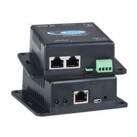
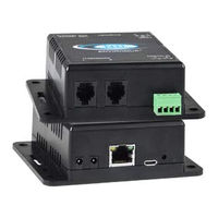
Micro Environment Monitoring System / Remote Temperature/Humidity Sensor over IP
Brand:
NTI
| Category:
Measuring Instruments
| Size: 4 MB
Table of Contents
Table of Contents
7
Introduction
10
Supported Web Browsers
11
Materials
11
Connectors and Leds
12
Installation
13
Mounting
13
DIN Clip Installation
13
Figure 1- Mount with Sensor Towards the Floor
13
Figure 2- DIN Clip Hardware
13
Connect Sensors
14
Figure 3- DIN Clips Installed
14
Figure 4- Connect Sensors
14
Figure 5- Terminal Block for Dry-Contact Sensors
15
Figure 6- Secure Liquid Detection Sensor with Tape
15
Figure 7- Portion of Water Sensor Configuration Page
16
Ethernet Connection
17
Figure 8- Connect E-MICRO to the Ethernet
17
Connect the Power
18
Cable Restraint
18
Figure 9- Connect the AC Adapter and Power-Up
18
Figure 10- Use Cable Restraint
18
Overview
19
Administration
19
General Functions
19
Security
20
Device Discovery Tool
21
How to Use the Device Discovery Tool
21
Figure 11- Device Discovery Tool
21
Operation Via Web Interface
22
Log in and Enter Password
22
Figure 12- Login Prompt to Access Web Interface
22
Figure 13- Summary Page
23
Summary
24
Figure 14- Summary Page
24
Figure 15-Sensor Values in Color Have Meaning
24
Figure 16- List of Alerts Configured
25
Sensor Settings
26
Alerts
26
Figure 17- Sensor Settings
26
Figure 18- List of Configured Alerts and Their Status
26
Configure Alerts
27
Figure 19- Select a Sensor to Add an Alert Configuration for
27
Figure 20- Alert Configuration Page for Temperature/Humidity Sensors
27
Figure 21- Enable "Use Sensor as Threshold
28
Figure 22- Alert Configuration for Digital Sensor- Minor Difference
29
Smart Alert
30
Figure 23- Smart Alerts Page
30
Figure 24- Sensor to be Used for a Predefined Event
30
Figure 25- Event Logical Function Diagram
32
Figure 26- Examples of Smart Alert Conditions
33
Administration
34
System Settings
34
Figure 27- System Settings Page
34
Network Configuration
36
Figure 28- Network Settings Page
36
Modbus TCP/IP Support
37
SNMP Settings
37
Figure 29- SNMP Settings
37
Email Server Settings
38
Figure 30- Email Server Settings
38
Figure 31- Email Server Setting- Gmail Server Type
39
Time Settings
41
Set Local Time
41
Figure 32- Time and Date Settings
41
Users
42
Figure 33- Users List
42
Figure 34- User2 Added- Ready to Configure
42
Figure 35- Initial User Settings
42
Figure 36- User Settings-Contact Settings
43
Figure 37- User Settings- User Active Schedule
44
Figure 38- IP Camera Monitoring
45
Figure 39- Configure IP Cameras
45
Update Firmware
46
Figure 40- Update Firmware Page
46
Log
47
View Event Log
47
Figure 41- Event Log Page
47
View Data Log
48
Figure 42- Data Log Page
48
Figure 43- Examples of Emailed Datalogs
49
IP Devices
50
Figure 44- IP Devices Listing-None Monitored yet
50
Figure 45- IP Device Configuration Page
50
Support
51
Logout
51
Figure 46- IP Device List with New Devices Added
51
Figure 47- Support
51
Figure 48- Logout
51
Operation Via Text Menu- ENVIROMUX
52
Connect to ENVIROMUX from Terminal through Ethernet
52
Figure 49- Terminal Connection through Ethernet Port
52
Figure 50- Text Menu Login Screen
52
Connect to ENVIROMUX from Command Line
53
Figure 51- Text Menu- Administrator Main Menu
53
Using the Text Menu
54
Monitoring
54
Figure 52- Text Menu-Monitoring Menu
54
Figure 53- Text Menu-Sensor Status
55
Figure 54- Text Menu- Digital Input Status
55
Figure 55- Text Menu-View IP Devices
56
Figure 56- Text Menu-Configure Sensors List
56
Display Network Settings
57
Figure 57- Text Menu-Network Settings
57
Restore Defaults Button
58
Figure 58- Location of Restore Defaults Button
58
How to Setup Email
59
Figure 59- Email Server Settings Example for Sending Emails
59
Figure 60- Make Sure Alert Is Configured to Send to One or more Groups
60
Figure 61- Configure User to Receive Alerts Via Email
60
Locating Oids
61
Reading SNMP Values with Paessler PRTG
64
Figure 62- Add New Device to PRTG
64
Figure 63-PRTG E-MICRO Sensor Addition
65
Figure 64-PRTG E-MICRO Alert Addition
66
Figure 65-PRTG E-MICRO Alert Settings
67
Figure 66-PRTG E-MICRO Alert Notification
68
Figure 67-PRTG E-MICRO Sensor List
68
Figure 68-PRTG E-MICRO Sensor Settings
69
Figure 69-PRTG E-MICRO Value Scaling
70
Modbus TCP/IP Support
71
Modbus TCP Function Codes Definition
71
Function Code 02 - Read the State of Digital Inputs
71
Function Code 04 - Read Sensors and Digital Input Values and Status
72
REST API Support
74
Technical Specifications
79
Troubleshooting
80
E-MICRO Email Error Codes
81
Index
82
Warranty Information
82
Advertisement
NTI ENVIROMUX E-MICRO-TRH Quick Installation Manual (2 pages)
Brand:
NTI
| Category:
Measuring Instruments
| Size: 0 MB
Advertisement
Related Products
NTI ENVIROMUX-5D
NTI ENVIROMUX-16D
NTI ENVIROMUX-2D
NTI ENVIROMUX-MINI-LXO
NTI ENVIROMUX-5DB
NTI ENVIROMUX-2DB
NTI ENVIROMUX E-MICRO-TRHP
NTI ENVIROMUX E-2D
NTI E-STHS-LSH
NTI ENVIROMUX E-5D
NTI Categories
Extender
Boiler
Switch
Media Converter
Cables and connectors
More NTI Manuals
Login
Sign In
OR
Sign in with Facebook
Sign in with Google
Upload manual
Upload from disk
Upload from URL