Table of Contents
Advertisement
Quick Links
Industrial Managed
Ethernet Switch –
User Manual
EHG77xx
.
Atop Technologies, Inc
Industrial Managed
Ethernet Switch
User Manual
V1.0
th
May 30
, 2024
Series covered by this manual:
EHG7704/EHG7706/EHG7708/EHG7708c/EHG7711 series
This PDF Document contains internal hyperlinks for ease of navigation.
For example, click on any item listed in the Table of Contents to go to that page.
Page 1 of 251
Advertisement
Table of Contents

Subscribe to Our Youtube Channel
Related Manuals for Atop EHG7704 Series


Summary of Contents for Atop EHG7704 Series
- Page 1 Industrial Managed Ethernet Switch – User Manual EHG77xx Atop Technologies, Inc Industrial Managed Ethernet Switch User Manual V1.0 May 30 , 2024 Series covered by this manual: EHG7704/EHG7706/EHG7708/EHG7708c/EHG7711 series This PDF Document contains internal hyperlinks for ease of navigation. For example, click on any item listed in the Table of Contents to go to that page.
- Page 2 Industrial Managed Ethernet Switch – User Manual EHG77xx Published by: Atop Technologies, Inc. 2F, No. 146, Sec. 1, Tung-Hsing Rd, 30261 Chupei City, Hsinchu County Taiwan, R.O.C. Tel: +886-3-550-8137 Fax: +886-3-550-8131 www.atoponline.com Page 2 of 251...
- Page 3 EHG77xx Important Announcement The information contained in this document is the property of Atop Technologies, Inc., and is supplied for the sole purpose of operation and maintenance of Atop Technologies, Inc., products. No part of this publication is to be used for any other purposes, and it is not to be reproduced, copied, disclosed, transmitted, stored in a retrieval system, or translated into any human or computer language, in any form, by any means, in whole or in part, without the prior explicit written consent of Atop Technologies, Inc.,...
-
Page 4: Table Of Contents
Industrial Managed Ethernet Switch – User Manual EHG77xx Table of Contents Introduction ........................14 Introduction to Industrial Managed Switch ..................... 14 Software Features ..........................15 Introduction to the Document ......................... 15 Configuring with a Web Browser ..................16 System ..............................18 2.1.1 Information ............................. - Page 5 Industrial Managed Ethernet Switch – User Manual EHG77xx 2.15.4 Port Scheduler ............................136 2.15.5 Port Shaping ............................139 2.15.6 Port Tag Remarking ..........................139 2.15.7 Port DSCP ............................141 2.15.8 DSCP-Based QoS ..........................142 2.15.9 DSCP Translation ..........................143 2.15.10 DSCP Classification ........................
- Page 6 Industrial Managed Ethernet Switch – User Manual EHG77xx 3.10 LLDP..............................225 3.10.1 Neighbors ............................. 225 3.10.2 Port Statistics ............................226 3.11 PTP............................... 228 3.11.1 PTP............................... 228 3.11.2 802.1AS Statistics ..........................229 3.12 MAC Table ............................230 3.13 VLANs ..............................231 3.13.1 Membership ............................
- Page 7 Industrial Managed Ethernet User Manual Switch – EHG77XX Figure 2.22 Webpage to Configure ERPS ....................... 35 Figure 2.23 After Clicking to Configure ERPS ....................36 Figure 2.24 Submenus under the DHCP Main Configuration Menu ................ 37 Figure 2.25 Webpage to Configure DHCPv4 Snooping ................... 38 Figure 2.26 Webpage to Configure DHCPv4 Relay ....................
- Page 8 Industrial Managed Ethernet User Manual Switch – EHG77XX Figure 2.78 Webpage to Configure Common Aggregation ..................98 Figure 2.79 Webpage to Configure Group Aggregation ..................99 Figure 2.80 Webpage to Configure LACP Aggregation ..................101 Figure 2.81 Webpage to Configure Bridge Settings of Spanning Tree ..............102 Figure 2.82 Webpage to Configure MSTI Mapping of Spanning Tree ..............
- Page 9 Industrial Managed Ethernet User Manual Switch – EHG77XX Figure 3.8 System Log Information Webpage ....................... 181 Figure 3.9 Detailed System Log Information Webpage ..................182 Figure 3.10 System’s Power Status Webpage ...................... 183 Figure 3.11 System’s Digital Input Webpage ......................183 Figure 3.12 Ports Group Menu under Monitor .......................
- Page 10 Industrial Managed Ethernet User Manual Switch – EHG77XX Figure 3.68 Detailed UDLD Status for Port 1 and Neighbour Status Webpage ............ 235 Figure 3.69 SD Card Status Webpage........................236 Figure 4.1 Diagnostics Menu ..........................237 Figure 4.2 Diagnostics Webpage using IPv4 Ping ....................237 Figure 4.3 Result of successful IPv4 ping ......................
- Page 11 Industrial Managed Ethernet User Manual Switch – EHG77XX Table 2.29 Descriptions of SNMP Access Configuration ..................56 Table 2.30 Descriptions of RMON Statistics ......................57 Table 2.31 Descriptions of RMON History ....................... 58 Table 2.32 Descriptions of RMON Alarm ......................... 59 Table 2.33 Descriptions of RMON Event .........................
- Page 12 Industrial Managed Ethernet User Manual Switch – EHG77XX Table 2.89 Descriptions of DSCP-Based Configuration of QoS ................142 Table 2.90 Descriptions of DSCP Translation Configuration of QoS ..............143 Table 2.91 Descriptions of DSCP Classification Configuration of QoS ..............144 Table 2.92 Descriptions of QoS Control List Configuration ...................
- Page 13 Industrial Managed Ethernet User Manual Switch – EHG77XX Table 3.46 Descriptions of LLDP Neighbour Information ..................226 Table 3.47 Monitoring Descriptions of LLDP Global and Statistics Local Counters ..........227 Table 3.48 Descriptions of PTP External Clock Mode and Clock Configuration ........... 228 Table 3.49 Descriptions of IEEE 802.1AS Statistics ....................
-
Page 14: Introduction
Atop’s managed switch is also an industrial switch and not a commercial switch. A commercial switch simply works in a comfortable office environment. However, an industrial switch is designed to perform in harsh industrial environments, i.e., extreme temperature, high humidity, dusty air, potential high impact, or the presence of... -
Page 15: Software Features
These protocols and software features allow the network administrator to implement security and reliability into their network. These features enable Atop’s switches to be used in safety applications, and factory and process automation. The followings are the list of protocols and software features. -
Page 16: Configuring With A Web Browser
2 Configuring with a Web Browser There are three ways to configure Atop’s Industrial Managed Ethernet Switch: Web browser, Telnet console, and Serial console. How to access the industrial managed switch through web browser is explained in Chapter 2 through Chapter 5. -
Page 17: Figure 2.2 Entering Credential On The Login Webpage
Industrial Managed Ethernet User Manual Switch – EHG77XX Figure 2.2 Entering Credential on the Login Webpage If user entered wrong credentials, users can try to re-enter the new username and password again until it is correct. Or users can simply click on the Cancel button to forfeit the process. If the login process was success, the user will be presented with the Port State Overview Webpage which shows the front panel of the managed switch, as shown in Figure 2.3. -
Page 18: System
2.1.1 Information This subsection describes how users can assign system’s details to the Atop’s switch. There are three fields in this System Information Configuration Webpage: System Contact, System Name, and System Location. By entering this unique and relevant system information, it will help identifying one specific switch among all the others in the network. -
Page 19: Figure 2.6 Configuration Webpage Of The System Information
The allowed string length is between 0 to 255. Note that the name entered here will also be shown in Atop’s Device Management Utility. System Input the physical location of this node (e.g., telephone Location closet, 3rd floor) in the system location. -
Page 20: Figure 2.7 Webpage To Configure System's Ip Information
Industrial Managed Ethernet User Manual Switch – EHG77XX Figure 2.7 Webpage to Configure System’s IP Information The first part, as shown in Figure 2.7, allows user to set the operating mode of the managed switch. Only “Host” mode is available for now. User can enter up to four Domain Name System (DNS) Servers. A DNS proxy option allows clients to set up the device as a DNS proxy server. -
Page 21: Figure 2.9 Ip Interfaces Part In The Configuration->System->Ip Submenu
Industrial Managed Ethernet User Manual Switch – EHG77XX Label Description Only an IPv4 DNS proxy is now supported. The second part of IP Setting section is the IP Interface part, as shown in Figure 2.9. User can choose to enable DHCP (Dynamic Host Configuration Protocol) for DHCPv4 and/or DHCPv6 by checking the boxes in the first subcolumn within these fields, as shown in red circles. -
Page 22: Figure 2.10 Ip Routes Part In The Configuration->System->Ip Submenu
Industrial Managed Ethernet User Manual Switch – EHG77XX Label Description The field may be left blank, if IPv4 operation on the interface or the DHCP fall- back address is not necessary. DHCPv6 -> Enable Enable the DHCPv6 client by checking this box. If this option is enabled, the system will configure the IPv6 address of the interface using the DHCPv6 protocol. -
Page 23: Ntp
2.1.3 Atop’s industrial managed switch has internal calendar (date) and clock (or system time) which can be set manually or automatically. Figure 2.11 shows the Network Time Protocol (NTP) configuration webpage. Here, users can automatically set the device’s time by first selecting Enabled from the drop-down menu of Mode field. Then, users must enter the IP or Domain address of up to the total of five NTP servers: Server1 to Server 5. -
Page 24: Time
Industrial Managed Ethernet User Manual Switch – EHG77XX Label Description Factory Default Sets the fifth IP or Domain address of NTP Server. Switch will locate the Server 5 NULL 5th NTP Server if if it fails to connect with the 4th NTP Server. 2.1.4 Time This Time webpage allows the user to configure the time zone and daylight saving for the managed switch. -
Page 25: Figure 2.12 Webpage To Configure System Time
Industrial Managed Ethernet User Manual Switch – EHG77XX Figure 2.12 Webpage to Configure System Time Table 2.6 Description of System Time Configuration Label Description Month Select the month of system time Date Select the date of system time Year Select the year of system time Hours Select the starting hour of system time Minutes... -
Page 26: Log
Industrial Managed Ethernet User Manual Switch – EHG77XX Label Description Minutes Number of minutes offset from UTC. This field is only available when Time Zone is set to Manual Setting. Acronym User can set the acronym of the time zone in this field (Range: Up to 16 characters). Notice the string '' is a special syntax that is reserved for null input. -
Page 27: Dip Switch
Industrial Managed Ethernet User Manual Switch – EHG77XX Figure 2.13 Webpage to Configure System -> Log Table 2.9 Descriptions of the System Log Configuration Default Field Detailed description value Indicates the server mode operation whether it is enabled or disabled. When Disabled it is enabled, the syslog message will be sent out to the remote syslog server. -
Page 28: Alert
Industrial Managed Ethernet User Manual Switch – EHG77XX Figure 2.14 Webpage to Configure System DIP Switch 2.1.7 Alert This webpage allows the users to configure how each type of the power status alarm events will be sent to or notify the users. -
Page 29: Smtp Setting
Industrial Managed Ethernet User Manual Switch – EHG77XX Label Description Factory Default Alarm LED Options: Disabled, Power On, or Power Off Disabled E-mail Options: Disabled, Power On, or Power Off Disabled 2.1.8 SMTP Setting Simple Mail Transfer Protocol (SMTP) is an internet standard for sending e-mail across IP networks. In case of any warning events, the system can send an alarm message (e.g., Link Status and System Log) to users by e-mail. -
Page 30: Ports
Industrial Managed Ethernet User Manual Switch – EHG77XX Figure 2.17 Example of SMTP Setting Table 2.11 Descriptions of SMTP Setting Label Description Factory Default SMTP Server Configure the IP address of an out-going e-mail server NULL Authentication By checking on the box, users Enable or disable an authentication login. -
Page 31: Figure 2.18 Webpage To Configure Ports Of Ehg7711
Industrial Managed Ethernet User Manual Switch – EHG77XX The transmission Speed of each port can be chosen from the dropdown list which could be 10 Mbps HDX, 10 Mbps FDX, 100 Mbps HDX, 100 Mbps FDX, and 1 Gbps FDX. The possible physical layer connections of each port are listed on the Adv Duplex and Adv speed column. - Page 32 Industrial Managed Ethernet User Manual Switch – EHG77XX Field Label Subfield Label Description Factory Default Warning Indicate a warning when there is a problem with the port. Grey colour Different colours are used to indicate the severity of port problem. : No warnings : There are warnings.
-
Page 33: Poe
To find out whether this function is supported or not by your managed switch, please look for the keyword “PoE” in Atop’s model name. If the switch has “PoE” in its model name, it means that the switch is a Power Sourcing Equipment (PSE) that can provide power output to a Powered Device (PD). -
Page 34: Erps
Figure 2.21 depicts an example of ring topology forming by four Atop’s managed switch series. Figure 2.21 An Example of Ring Topology (a) Major Ring, and (b) Sub-Ring An ERPS ring consists of interconnected Layer 2 switching devices configured with the same control VLAN. -
Page 35: Figure 2.22 Webpage To Configure Erps
Industrial Managed Ethernet User Manual Switch – EHG77XX Figure 2.22 shows the ERPS Configuration webpage, and Table 2.14 summarizes the descriptions of columns in EPRS Configuration’s table. Figure 2.22 Webpage to Configure ERPS Table 2.14 Description of EPRS Configuration Table Label Description ERPS #... -
Page 36: Figure 2.23 After Clicking To Configure Erps
Industrial Managed Ethernet User Manual Switch – EHG77XX Figure 2.23 After Clicking to Configure ERPS Table 2.15 shows the descriptions of each field and subfields in the ERPs configuration webpage in details. Table 2.15 Descriptions of ERPS Configuration Webpage Field Label Subfiel Description Factory Default... -
Page 37: Dhcpv4
2.5 DHCPv4 Atop’s EHG77XX managed switch can act as a DHCPv4 (Dynamic Host Configuration Protocol over IP version 4) server in the local network. By enabling this function in the managed switch, an IPv4 address and related fields will be automatically assigned and delivered by the DHCPv4 server running inside the managed switch to other network devices connected to the managed switch. -
Page 38: Relay
To protect against a network security attack of rogue DHCP server or DHCP spoofing attack, Atop’s EHG77XX provide DHCP Snooping feature. When this feature is enabled on specific port(s) of EHG77XX managed switch, the EHG77XX will allow the DHCP messages from trusted ports to pass through while it will discard or filter the DHCP messages from untrusted ports. -
Page 39: Figure 2.26 Webpage To Configure Dhcpv4 Relay
Industrial Managed Ethernet User Manual Switch – EHG77XX A relay agent relays DHCP/BOOTP messages that are broadcast on one of its connected physical interfaces, such as a network adapter, to other remote subnets to which it is connected by other physical interfaces. Figure 2.26 shows the DHCP Relay configuration webpage. -
Page 40: Security
Drop: Drop the package when received a DHCP message. 2.6 Security Security Configuration of Atop’s EHG77XX managed switch consists of three main parts: Switch, Network, and AAA. There are a number of submenus for each of these main security configuration parts, as shown in Figure 2.27. -
Page 41: Figure 2.28 Configuration-> Security -> Switch Menu
Industrial Managed Ethernet User Manual Switch – EHG77XX Figure 2.28 Configuration-> Security -> Switch Menu 2.6.1.1 Switch Users A simple way of providing terminal access control in your network device (managed switch) is to use passwords and assign privilege levels. Password protection restricts access to a network or network device. Privilege levels define what commands users can enter after they have logged into a network device. -
Page 42: Figure 2.30 Webpage To Configure Security Switch Users - After Clicked Add New User Button
Industrial Managed Ethernet User Manual Switch – EHG77XX Users can also click Add New User button to add a new user. After clicked, the webpage in Figure 2.30 will be shown. Table 2.19 summarizes the descriptions of the Add User webpage. When clicking on Configuration- >Security->Switch->Users submenu, there is a hyperlink in each username where users can click to Edit user. -
Page 43: Figure 2.32 Webpage To Configure Privilege Levels Of The Switch
Industrial Managed Ethernet User Manual Switch – EHG77XX Group Name is the name identifying the privilege group. In most cases, a privilege level group consists of a single module (e.g., LACP, RSTP or QoS), but a few of them contains more than one. Table 2.20 shows examples of some group name in details: Table 2.20 Examples of Group Name Label... -
Page 44: Figure 2.33 Webpage To Configure Switch Authentication Method
Industrial Managed Ethernet User Manual Switch – EHG77XX Authorization Method configuration, and Accounting Method Configuration webpage, as shown in Figure 2.33. In the Authentication Method Configuration, users can configure how a user is authenticated when he/she logs into the switch via one of the management client interfaces. In Command Authorization Method configuration, users can configure the limitation of the CLI commands available to a user. -
Page 45: Figure 2.34 Webpage To Configure Ssh
Industrial Managed Ethernet User Manual Switch – EHG77XX Label Description Factory Default • Tacacs: Use remote TACACS+ server(s) for command authorization. If all remote servers are offline, the user is granted access to CLI commands according to his privilege level. Cmd Lvl Authorize all commands with a privilege level higher than or equal to this level. -
Page 46: Figure 2.35 Webpage To Https Configuration
Industrial Managed Ethernet User Manual Switch – EHG77XX Figure 2.35 Webpage to HTTPS Configuration If the user selects the Upload option for Certificate Maintain field, the webpage will be updated with additional fields which are Certificate Pass Phrase, Certificate Upload, and File Upload, as shown in Figure 2.36. Table 2.22 summarizes the descriptions of fields in HTTPS Configuration webpage. - Page 47 The Atop’s managed switch support SNMP and can be configured in this section. Within the SNMP submenu, there are seven submenus under it: System, Trap, Communities, Users, Groups, Views, and Access.
-
Page 48: Figure 2.37 Webpage To Configure Snmp System
Industrial Managed Ethernet User Manual Switch – EHG77XX Figure 2.37 Webpage to Configure SNMP System 2.6.1.7 SNMP Trap Destinations The managed switch provides a trap function that allows switch to send notification to agents with SNMP traps or inform. The notifications are based on the status changes of the switch such as link up, link down, warm start, and cold start. -
Page 49: Figure 2.39 Adding New Entry To Snmp Trap Destination Table
Industrial Managed Ethernet User Manual Switch – EHG77XX Figure 2.39 Adding New Entry to SNMP Trap Destination Table Table 2.23 Descriptions of SNMP Trap Destination Configurations Label Description Delete Users are allowed to delete each entry separately. Name Indicates the trap Configuration's name. Indicates the trap destination's name. Indicates the trap destination mode operation. -
Page 50: Figure 2.40 Webpage To Configure Snmp Trap Sources
Industrial Managed Ethernet User Manual Switch – EHG77XX Figure 2.40 Webpage to Configure SNMP Trap Sources Figure 2.41 Adding New Entry to SNMP Trap Sources Table 2.24 Description of SNMP Trap Source Configurations Label Description Delete Click this button to delete the entry. It will be deleted during the next save. Users are allowed to delete each entry separately. -
Page 51: Figure 2.42 Webpage To Configure Snmp Communities
Industrial Managed Ethernet User Manual Switch – EHG77XX Label Description The first character must not begin with asterisk (*) and the maximum of OID count must not exceed 128. 2.6.1.9 SNMP Communities This submenu allows users to configure SNMP community table as shown in Figure 2.42. The entry index key is Community. -
Page 52: Figure 2.44 Webpage To Configure Snmp Users
Industrial Managed Ethernet User Manual Switch – EHG77XX Label Description Indicates the community secret (access string) which is used to permit access using Community Secret SNMPv1 and SNMPv2c to the SNMP agent. The allowed string length is between 1 to 32, and the allowed content is ASCII characters from 33 to 126. - Page 53 Industrial Managed Ethernet User Manual Switch – EHG77XX Label Description Factory Default system engine ID then it is a local user; otherwise it is a remote user. A string identifying the user name that this entry should belong User Name to.
-
Page 54: Figure 2.45 Webpage To Configure Snmp Groups
Industrial Managed Ethernet User Manual Switch – EHG77XX Figure 2.45 Webpage to Configure SNMP Groups Table 2.27 Descriptions of SNMP Groups Label Description Factory Default Check here if user wants to delete the entry. It will be deleted during the Delete next save. -
Page 55: Figure 2.46 Webpage To Configure Snmp Views
Industrial Managed Ethernet User Manual Switch – EHG77XX Figure 2.46 Webpage to Configure SNMP Views Table 2.28 Descriptions of SNMP Views Label Description Factory Default Check here if user wants to delete the entry. It will be deleted during the next Delete save. -
Page 56: Figure 2.47 Webpage To Configure Snmp Access
2.6.1.14 RMON Statistics Figure 2.48 shows RMON (Remote Network Monitoring) Statistics Configuration. Atop’s managed switch can monitor network traffic on remote Ethernet segment to detect problem inside the network. The entry index key is ID for RMON Statistics table. -
Page 57: Figure 2.48 Webpage To Configure Rmon Statistics
Industrial Managed Ethernet User Manual Switch – EHG77XX Figure 2.48 Webpage to Configure RMON Statistics Figure 2.49 Adding New Entry to RMON Statistics Configuration Table 2.30 Descriptions of RMON Statistics Label Description Factory Default Delete Click here to delete the entry. It will be deleted during the next save. Indicates the index of the entry. -
Page 58: Figure 2.50 Webpage To Configure Rmon History
Industrial Managed Ethernet User Manual Switch – EHG77XX Figure 2.50 Webpage to Configure RMON History Figure 2.51 Adding New Entry to RMON History Table Table 2.31 Descriptions of RMON History Label Description Factory Default Click here to delete the entry. It will be deleted during the next Delete save. -
Page 59: Figure 2.52 Webpage To Configure Rmon Alarm
Industrial Managed Ethernet User Manual Switch – EHG77XX Figure 2.52 Webpage to Configure RMON Alarm Table 2.32 Descriptions of RMON Alarm Label Description Factory Default Click here to delete the entry. It will be deleted during the next Delete save. Indicates the index of the entry. -
Page 60: Figure 2.53 Webpage To Configure Rmon Event
Industrial Managed Ethernet User Manual Switch – EHG77XX Label Description Factory Default threshold. RisingOrFallingTrigger alarm when the first value is larger than the rising threshold or less than the falling threshold (default). Rising Rising threshold value (-2147483648 - 2147483647). Threshold Rising event index (0-65535). -
Page 61: Network
Industrial Managed Ethernet User Manual Switch – EHG77XX 2.6.2 Network Under this SecurityNetwork submenus, the users can configure network security for the EHG77XX managed switch. Figure 2.54 shows list of menus under the SecurityNetwork. Under this section, users can setup security for port, network access server (NAS), access control list (ACL), IP source guard, and ARP (Address Resolution Protocol) inspection. -
Page 62: Figure 2.55 Webpage To Configure Network Port Security
Industrial Managed Ethernet User Manual Switch – EHG77XX Figure 2.55 Webpage to Configure Network Port Security Table 2.34 Descriptions of Port Security Configuration Label Description Factory Default Global Configuration Aging If checked, secured MAC addresses are subject to aging as discussed Disabled Enabled under... - Page 63 Industrial Managed Ethernet User Manual Switch – EHG77XX Label Description Factory Default primarily to ensure that the same MAC address doesn't give rise to continuous notifications (if notifications on violation count is enabled). Port Configuration Port The port number to which the configuration below applies. Port no.
-
Page 64: Figure 2.56 Webpage To Configure Network Port Security Mac Addresses
Industrial Managed Ethernet User Manual Switch – EHG77XX 2.6.2.2 Port Security MAC Addresses In this webpage as shown in Figure 2.56, the users may add and delete static and sticky MAC addresses managed by Port Security. The port security defines three types of MAC addresses, of which static and sticky can be added and removed on this page: ... - Page 65 Industrial Managed Ethernet User Manual Switch – EHG77XX Label Description Factory Default VLAN ID The VLAN ID in question. MAC Address The MAC address in question. 00:00:00:00:00:00 Indicates the type of entry and may be either Static or Sticky (see Static Type description above).
-
Page 66: Figure 2.57 Webpage To Configure Network Nas
Industrial Managed Ethernet User Manual Switch – EHG77XX Figure 2.57 Webpage to Configure Network NAS Table 2.36 Descriptions of Network NAS Label Description Factory Default System Configuration Indicates if NAS is enabled or disabled on the switch globally. If Mode Disabled disabled globally, all ports are allowed forwarding of frames. - Page 67 Industrial Managed Ethernet User Manual Switch – EHG77XX Label Description Factory Default parameter controls exactly this period of time and can be set to a number between 10 and 1000000 seconds. If reauthentication is enabled and the port is in an 802.1X-based mode, supplicants that are no longer attached to the port will get removed upon the next reauthentication.
- Page 68 Industrial Managed Ethernet User Manual Switch – EHG77XX Label Description Factory Default This is the value that a port's Port VLAN ID is set to if a port is moved into the Guest VLAN. It is only changeable if the Guest Guest VLAN ID VLAN option is globally enabled.
- Page 69 Industrial Managed Ethernet User Manual Switch – EHG77XX Label Description Factory Default supplicant. Note: Suppose two backend servers are enabled and that the server timeout is configured to X seconds (using the AAA configuration page), and suppose that the first server in the list is currently down (but not considered dead).
- Page 70 Industrial Managed Ethernet User Manual Switch – EHG77XX Label Description Factory Default • Port-based 802.1X • Single 802.1X RADIUS attributes used in identifying a QoS Class: The User-Priority-Table attribute defined in RFC4675 forms the basis for identifying the QoS Class in an Access-Accept packet. Only the first occurrence of the attribute in the packet will be considered, and to be valid, it must follow this rule: •...
- Page 71 Industrial Managed Ethernet User Manual Switch – EHG77XX Label Description Factory Default For trouble-shooting VLAN assignments, use the "Monitor→VLANs→VLAN Membership and VLAN Port" pages. These pages show which modules have (temporarily) overridden the current Port VLAN configuration. Guest VLAN Operation: When a Guest VLAN enabled port's link comes up, the switch starts transmitting EAPOL Request Identity frames.
-
Page 72: Figure 2.58 Access Control List's Submenus
Industrial Managed Ethernet User Manual Switch – EHG77XX Click Refresh button to refresh the page. Click Save button to save changes. Click Reset button to undo any changes made locally and revert to previously saved values. 2.6.2.4 ACL (Access Control List) is the list table of ACEs, containing Access Control Entries that specify individual users or groups permitted or denied to specific traffic objects, such as a process or a program. -
Page 73: Figure 2.59 Webpage To Configure Network Acl Ports
Industrial Managed Ethernet User Manual Switch – EHG77XX Figure 2.59 Webpage to Configure Network ACL Ports Table 2.37 Descriptions of Network ACL Ports Label Description Factory Default Port The logical port for the settings contained in the same row. Port ID from 1 to 11 Select the policy to apply to this port. -
Page 74: Figure 2.60 Webpage To Configure Network Acl Rate Limiters
Industrial Managed Ethernet User Manual Switch – EHG77XX Label Description Factory Default Enabled: Port shut down feature is enabled. If a frame is received on the port, the port will be disabled. Disabled: Port shut down feature is disabled. The default value is "Disabled". -
Page 75: Figure 2.61 Webpage To Configure Network Acl Access Control
Industrial Managed Ethernet User Manual Switch – EHG77XX The valid rate is 0 - 99, 100, 200, 300, ..., 1092000 in Rate pps or 0, 100, 200, 300, ..., 1000000 in kbps. Specify the rate unit. The allowed values are: Unit pps: packets per second. - Page 76 Industrial Managed Ethernet User Manual Switch – EHG77XX - ARP: The ACE will match ARP/RARP frames. - IPv4: The ACE will match all IPv4 frames. - IPv4/ICMP: The ACE will match IPv4 frames with ICMP protocol. - IPv4/UDP: The ACE will match IPv4 frames with UDP protocol. - IPv4/TCP: The ACE will match IPv4 frames with TCP protocol.
-
Page 77: Figure 2.62 Webpage To Configure Network Acl After Clicked + Sign To Add A New Entry
Industrial Managed Ethernet User Manual Switch – EHG77XX Figure 2.62 Webpage to Configure Network ACL After Clicked + Sign to Add a New Entry Table 2.40 Description of ACL Configuration Label Description Ingress Select the ingress port for which this ACE is applied to the matching rule. Port All: The ACE is applied to all port. -
Page 78: Figure 2.63 Configuration->Security->Network->Acl-> Access Control List Submenu: Add New Entry: Frame Type Ethernet Type
Industrial Managed Ethernet User Manual Switch – EHG77XX Label Description Rate Specify the rate limiter in the number of base units. The allowed value is ranging Limiter between 1 to 16. Disabled option indicates that the rate limiter operation is disabled. Port Frames that are matched to this ACE will be redirected to the port number specified here. -
Page 79: Table 2.41 Description Of Acl Configuration With Mac Parameters
Industrial Managed Ethernet User Manual Switch – EHG77XX Table 2.41 Description of ACL Configuration with MAC Parameters Label Description SMAC (Only displayed when the frame type is Ethernet Type or ARP.) Filter Specify the source MAC address (SMAC) that is used for filtering with this ACE. Any: Choose this option if do not want to specify any source MAC address for filtering with this ACE. -
Page 80: Figure 2.64 Configuration->Security->Network->Acl-> Access Control List Submenu: Add New Entry: Frame Type Arp
Industrial Managed Ethernet User Manual Switch – EHG77XX Figure 2.64 Configuration->Security->Network->ACL-> Access Control List Submenu: Add New Entry: Frame Type ARP Table 2.43 Description of ACL Configuration with ARP Parameters Label Description Factory Default ARP/RARP Specify the available ARP/RARP opcode (OP) flag for this ACE. Any: No ARP/RARP OP flag is specified. - Page 81 Industrial Managed Ethernet User Manual Switch – EHG77XX Label Description Factory Default Sender IP Mask When "Network" is selected for the sender IP filter, you can enter a 255.255.255.0 specific sender IP mask in dotted decimal notation. Target IP Filter Specify the target IP filter for this specific ACE.
-
Page 82: Figure 2.65 Configuration->Security->Network->Acl-> Access Control List Submenu: Add New Entry: Frame Type Ipv4
Industrial Managed Ethernet User Manual Switch – EHG77XX Figure 2.65 Configuration->Security->Network->ACL-> Access Control List Submenu: Add New Entry: Frame Type IPv4 Table 2.44 Description of ACL Configuration with IPv4 Parameters Label Description Factory Default IP Protocol Specify the IP protocol filter for this ACE. Filter Any: No IP protocol filter is specified ("don't-care"). - Page 83 Industrial Managed Ethernet User Manual Switch – EHG77XX Label Description Factory Default Specify the fragment offset settings that will be matched with this ACE. This Fragment involves the settings for the More Fragments (MF) bit and the Fragment Offset (FRAG OFFSET) field for an IPv4 frame. No: IPv4 frames where the MF bit is set or the FRAG OFFSET field is greater than zero, will not be filtered with this entry.
-
Page 84: Figure 2.66 Configuration->Security->Network->Acl-> Access Control List Submenu: Add New Entry: Frame Type Ipv6
Industrial Managed Ethernet User Manual Switch – EHG77XX Figure 2.66 Configuration->Security->Network->ACL-> Access Control List Submenu: Add New Entry: Frame Type IPv6 Table 2.45 Description of ACL Configuration with IPv6 Parameters Label Description Factory Default Next Specify the IPv6 next header filter for this ACE. Header Any: No IPv6 next header filter is specified ("don't-care"). -
Page 85: Table 2.46 Description Of Acl Configuration With Icmp Parameters
Industrial Managed Ethernet User Manual Switch – EHG77XX Label Description Factory Default this bit is "don't-care". The real matched pattern is [sipv6_address & sipv6_bitmask] (last 32 bits). For example, if the SIPv6 address is 2001::3 and the SIPv6 bitmask is 0xFFFFFFFE (bit 0 is "don't-care"... -
Page 86: Table 2.48 Description Of Acl Configuration With Ethernet Type Parameters
Industrial Managed Ethernet User Manual Switch – EHG77XX Label Description Factory Default TCP/UDP When "Range" is selected for the TCP/UDP source filter, you can enter a Source Range specific TCP/UDP source range value. The allowed range is 0 to 65535. A frame that hits this ACE matches this TCP/UDP source value. -
Page 87: Figure 2.67 Configuration->Security->Network->Ip Source Guard Submenus
Industrial Managed Ethernet User Manual Switch – EHG77XX Specific: If you want to filter a specific Ethernet Type with this ACE, you can enter a specific Ethernet Type value here. When “Specific” option is selected, a field for entering an EtherType value will be appeared. Ethernet When "Specific"... -
Page 88: Figure 2.68 Webpage To Ip Source Guard Configuration
Industrial Managed Ethernet User Manual Switch – EHG77XX Figure 2.68 Webpage to IP Source Guard Configuration Table 2.49 Descriptions of Network IP Source Guard Configuration Label Description Factory Default IP Source Guard Configuration Enable or Disable the Global IP Source Guard. Note that, for a port to actually is enabled, user must also select “enabled”... -
Page 89: Figure 2.69 Webpage To Configure Network Ip Source Guard Static Table
Industrial Managed Ethernet User Manual Switch – EHG77XX Figure 2.69 Webpage to Configure Network IP Source Guard Static Table Table 2.50 Descriptions of Network IP Source Guard Static Label Description Factory Default Click entry Delete button to delete the entry. It will be deleted during the Delete next save. -
Page 90: Figure 2.70 Arp Inspection Menu
Industrial Managed Ethernet User Manual Switch – EHG77XX Figure 2.70 ARP Inspection Menu 2.6.2.8.1 Port Configuration To configure ARP Inspection for port(s) on the managed switch, the users can use the webpage shown in Figure 2.71. There are two parts here: ARP Inspection Configuration, and Port Mode Configuration. Under the ARP Inspection Configuration part, user have to globally enable the ARP Inspection by selecting “Enabled”... -
Page 91: Table 2.51 Descriptions Of Arp Inspection Port Configuration
Industrial Managed Ethernet User Manual Switch – EHG77XX Table 2.51 Descriptions of ARP Inspection Port Configuration Label Description Factory Default ARP Inspection Configuration Mode Enable or Disable the Global ARP Inspection. Disabled Port Mode Configuration Port Indicates port number. Enable or Disable ARP Inspection on any specific ports. ARP Inspection is only enabled on a given port when clicking “Enabled”... -
Page 92: Figure 2.72 Vlan Configuration Webpage Within Network->Arp Inspection Submenus
Industrial Managed Ethernet User Manual Switch – EHG77XX Figure 2.72 VLAN Configuration Webpage within Network->ARP Inspection Submenus Table 2.52 Descriptions of ARP Inspection VLAN Table Label Description Factory Default Click “Delete” button in each entry in you want to delete it. Delete Specify which VLANs that the ARP Inspection is enabled on. -
Page 93: Figure 2.73 Webpage To Configure Static Arp Inspection Static Table
Industrial Managed Ethernet User Manual Switch – EHG77XX Figure 2.73 Webpage to Configure Static ARP Inspection Static Table Table 2.53 Descriptions of Static ARP Inspection Table Label Description Factory Default Click “Delete” button to delete the entry. It will be deleted during the Delete next save. -
Page 94: Aaa
Industrial Managed Ethernet User Manual Switch – EHG77XX Figure 2.74 Webpage to Configure Dynamic ARP Inspection Table Table 2.54 Descriptions of Dynamic ARP Inspection Table Label Description Factory Default Starting port number of the switch that are displayed in Port Port1 the entries. -
Page 95: Figure 2.75 Webpage To Configure Aaa Radius
Industrial Managed Ethernet User Manual Switch – EHG77XX log of every management session used to access EHG77XX switches. You can use this information to generate reports for troubleshooting and auditing purposes. You can store accounting logs locally or send them to remote AAA servers. -
Page 96: Table 2.56 Comparison Of Authentication Server Settings Between Radius And Tacacs
Industrial Managed Ethernet User Manual Switch – EHG77XX Label Description Factory Default already determined as dead. The valid value of this field is an integer number ranging between 0 to 1440 minutes. To enable this feature, in case of more than one configured server, set the Deadtime to a value greater than 0 (zero). -
Page 97: Figure 2.76 Webpage To Configure Aaa Tacacs
Industrial Managed Ethernet User Manual Switch – EHG77XX Multiprotocol Yes, support AppleTalk Remote Support Access (ARA) and NetBIOS protocol Confidentiality Only password is encrypted Entire packet is encrypted Figure 2.76 shows the TACACS+ Server Configuration webpage. It consists of Global Configuration and Server Configuration parts. -
Page 98: Aggregation
Aggregation is a technique to use multiple ports in parallel to increase the link speed beyond the limits of a port and to increase the redundancy for higher availability. Atop’s EHG77XX allows the aggregation on its ports. Figure 2.77 lists the submenus under the ConfigurationAggregation. -
Page 99: Groups
Industrial Managed Ethernet User Manual Switch – EHG77XX Table 2.58 Descriptions of Common Aggregation Configuration Label Description Factory Default Hash Code Contributors The Source MAC address can be used to calculate the destination port for Checked Source MAC the frame. Check to enable the use of the Source MAC address or uncheck Address to disable it. -
Page 100: Lacp
Industrial Managed Ethernet User Manual Switch – EHG77XX Table 2.59 Descriptions of Aggregation Group Configuration Label Description Factory Default Indicates the aggregation group ID for the settings within the same row. Group Group ID ID "Normal" indicates that there is no aggregation. Only one group ID is valid per port. -
Page 101: Spanning Tree
RSTP (Rapid Spanning Tree Protocol), IEEE 802.1W, is also supported in Atop’s managed switches. It is an evolution of the STP, but it is still backwards compatible with standard STP. RSTP has the advantage over the... -
Page 102: Bridge Settings
Industrial Managed Ethernet User Manual Switch – EHG77XX STP. When there is a topology change such as link failure in the network, the RSTP will converge significantly faster to a new spanning tree topology. RSTP improves convergence on point-to-point links by reducing the Max- Age time to 3 times Hello interval, removing the STP listening state, and exchanging a handshake between two switches to quickly transition the port to forwarding state. -
Page 103: Msti Mapping
Industrial Managed Ethernet User Manual Switch – EHG77XX Label Description Factory Default For MSTP operation, this is the priority of the CIST. Otherwise, this is the priority of the STP/RSTP bridge. The interval between sending STP BPDU's. Valid values are in the range of 1 to 10 seconds. -
Page 104: Figure 2.82 Webpage To Configure Msti Mapping Of Spanning Tree
Industrial Managed Ethernet User Manual Switch – EHG77XX Figure 2.82 Webpage to Configure MSTI Mapping of Spanning Tree Table 2.62 Descriptions of Bridge Priorities Configuration of Spanning Tree Label Description Factory Default Configuration Identification The name identifying the VLAN to MSTI mapping. Bridges must share DUT’s Configuration the name and revision (see below), as well as the VLAN-to-MSTI... -
Page 105: Msti Priorities
Industrial Managed Ethernet User Manual Switch – EHG77XX 2.8.3 MSTI Priorities MSTI Priorities webpage is shown in Figure 2.83. This page allows the user to inspect and/or change the current STP MSTI bridge instance priority configurations. Table 2.63 summarizes the description of parameters under MSTI Configuration. -
Page 106: Figure 2.84 Webpage To Configure Cist Ports Of Spanning Tree
Industrial Managed Ethernet User Manual Switch – EHG77XX Figure 2.84 Webpage to Configure CIST Ports of Spanning Tree Table 2.64 Descriptions of CIST Ports Configuration of Spanning Tree Label Description Factory Default CIST Aggregated Port Configuration Port Indicates the switch port number of the logical STP port. STP Enabled Clicked to enable STP on this switch port. - Page 107 Industrial Managed Ethernet User Manual Switch – EHG77XX Label Description Factory Default Root Port has been selected. If set, it can cause lack of spanning tree connectivity. It can be set by a network administrator to prevent bridges external to a core region of the network influence the spanning tree active topology, possibly because those bridges are not under the full control of the administrator.
-
Page 108: Msti Ports
Industrial Managed Ethernet User Manual Switch – EHG77XX Label Description Factory Default active topology, possibly because those bridges are not under the full control of the administrator. This feature is also known as Root Guard. If enabled, this option restricts the port from propagating the received topology change and its notifications to other ports. -
Page 109: Ipmc
Industrial Managed Ethernet User Manual Switch – EHG77XX Figure 2.86 Example of MST1 in the MSTI Port Configuration Table 2.65 Descriptions of MSTI Configuration of Spanning Tree Label Description Factory Default Indicates the switch port number of the corresponding STP Port MST1 CIST (and MSTI) port. -
Page 110: Igmp Snooping
Industrial Managed Ethernet User Manual Switch – EHG77XX Figure 2.87 Configuration->IPMC Menu 2.9.1 IGMP Snooping IGMP is an acronym for Internet Group Management Protocol. It is a communications protocol used to manage the membership of Internet Protocol multicast groups. IGMP is used by IP hosts and adjacent multicast routers to establish multicast group memberships. -
Page 111: Table 2.66 Descriptions Of Igmp Snooping Within An Ipmc Profile
Industrial Managed Ethernet User Manual Switch – EHG77XX Table 2.66 Descriptions of IGMP Snooping within an IPMC Profile Label Description Factory Default IGMP Snooping Configuration Snooping Enabled Click to enable the Global IGMP Snooping. Checked Click to enable unregistered IPMCv4 traffic flooding. The flooding Unregistered control takes effect only when IGMP Snooping is enabled. -
Page 112: Figure 2.89 Webpage To Configure Igmp Snooping's Vlan For An Ipmc Profile
Industrial Managed Ethernet User Manual Switch – EHG77XX Figure 2.89 Webpage to Configure IGMP Snooping’s VLAN for an IPMC Profile Table 2.67 Descriptions of IGMP Snooping’s VLAN Configuration for an IPMC Profile Label Description Factory Default VLAN ID The VLAN ID of the entry. Snooping Check to enable the per-VLAN IGMP Snooping. -
Page 113: Mld Snooping
Industrial Managed Ethernet User Manual Switch – EHG77XX Label Description Factory Default tenths of seconds, where the default value is 10 in tenths of seconds (1 second). This setting is for Unsolicited Report Interval (URI), which is the time between repetitions of a host's initial report of membership in a group. - Page 114 Industrial Managed Ethernet User Manual Switch – EHG77XX Label Description Factory Default MLD Snooping Configuration Assign a valid IPv6 multicast address as prefix with a prefix length (from 8 to 128) for the range. Leave Proxy Click enable MLD Leave Proxy. This feature can be used to avoid Unchecked Enabled forwarding unnecessary leave messages to the router side.
-
Page 115: Figure 2.91 Webpage To Configure Mld Snooping's Vlan For An Ipmc Profile
Industrial Managed Ethernet User Manual Switch – EHG77XX Figure 2.91 Webpage to Configure MLD Snooping’s VLAN for an IPMC Profile Table 2.69 Descriptions of MLD Snooping’s VLAN Configuration for an IPMC Profile Label Description Factory Default VLAN ID Indicates the VLAN ID of the entry. MLD Snooping Check to enable the per-VLAN MLD Snooping. -
Page 116: Lldp
Industrial Managed Ethernet User Manual Switch – EHG77XX Label Description Factory Default This setting indicates the unsolicited Report Interval, which is the time between repetitions of a node’s initial report of interest in a multicast address. URI (sec) The allowed value is ranging between 0 to 31744 seconds, where the default value is 1 second. -
Page 117: Table 2.70 Descriptions Of Lldp Configuration
Industrial Managed Ethernet User Manual Switch – EHG77XX Table 2.70 Descriptions of LLDP Configuration Label Description Factory Default LLDP Parameters The switch periodically transmits LLDP frames to its neighbours for having the network discovery information up-to-date. Tx Interval is the interval Tx Interval between each LLDP frames. -
Page 118: Synce
Industrial Managed Ethernet User Manual Switch – EHG77XX Label Description Factory Default Note: When CDP awareness on an interface is disabled the CDP information isn't removed immediately, but gets removed when the hold time is exceeded. Optional When checked, the "port description" is included in LLDP transmitted TLV - Port Unchecked information. -
Page 119: Figure 2.93 Webpage To Configure Synce
Industrial Managed Ethernet User Manual Switch – EHG77XX Figure 2.93 Webpage to Configure SyncE Table 2.71 Description of SyncE Configuration Label Description Factory Default Clock Source Nomination and State This is the instance number of the clock source. This has to be referenced Clock Source when selecting 'Manual' Mode. - Page 120 Industrial Managed Ethernet User Manual Switch – EHG77XX Label Description Factory Default quality, which means lowest quality compared to clock source with known quality. The Hold Off timer value. Active loss of clock Source will be delayed the Disabled Hold Off selected amount of time.
-
Page 121: Mac Table
Industrial Managed Ethernet User Manual Switch – EHG77XX Label Description Factory Default Top: Clock selector is locked to Time over packets, e.g. PTP (See next field). Indicates the clock source that is locked to when clock selector is in locked Clock Source state. -
Page 122: Figure 2.94 Webpage To Configure Mac Table
Industrial Managed Ethernet User Manual Switch – EHG77XX Figure 2.94 Webpage to Configure MAC Table Table 2.72 Description of MAC Address Table Configuration Label Description Factory Default Aging Configuration Disable the automatic aging of dynamic entries by checking Unchecked Disable Automatic Aging the box. -
Page 123: Vlans
Industrial Managed Ethernet User Manual Switch – EHG77XX Label Description Factory Default Note: The static entries in the MAC table are shown in this table. The static MAC table can contain 64 entries at most. The MAC table is first sorted by VLAN ID and then by MAC address. Click here to delete the entry. -
Page 124: Figure 2.96 Webpage For Vlans Configuration
Industrial Managed Ethernet User Manual Switch – EHG77XX Figure 2.96 Webpage for VLANs Configuration Table 2.73 Description of Global VLAN Configuration Label Description Factory Default This field shows the allo1,10-13,200,300wed Access VLANs, i.e. it only affects ports configured as Access ports. Ports in other modes are members of the VLANs specified in the Allowed VLANs field. - Page 125 Industrial Managed Ethernet User Manual Switch – EHG77XX Label Description Factory Default Discards all frames that are not classified to the Access VLAN On egress, all frames are transmitted untagged. Trunk: Trunk ports can carry traffic on multiple VLANs simultaneously, and are normally used to connect to other switches.
- Page 126 Industrial Managed Ethernet User Manual Switch – EHG77XX Label Description Factory Default Note: If the S-port is configured to accept Tagged and Untagged frames (see Ingress Acceptance field below), frames with a C-tag are treated like frames with an S- tag.
-
Page 127: Svl
Industrial Managed Ethernet User Manual Switch – EHG77XX Label Description Factory Default All frames, whether classified to the Port VLAN or not, are transmitted without a tag. This option is only available for ports in Hybrid mode. In Trunk and Hybrid mode, ports may control which VLANs they are allowed to become members of. -
Page 128: Vcl
Industrial Managed Ethernet User Manual Switch – EHG77XX Label Description Factory Default The syntax is as follows: Individual VLANs are separated by commas. Range of VLANs are specified with a dash, which is separating the lower and the upper bound. The following example: 1, 10-13, 200, 300 will map to VLAN 1, 10, 11, 12, 13, 200, and 300. -
Page 129: Protocol-Based Vlan
Industrial Managed Ethernet User Manual Switch – EHG77XX Label Description Factory Default unchecked. By default, no ports are members of the mapping entry, and so all boxes are unchecked. Click Add New Entry button to add a new MAC to VLAN ID mapping entry. An empty row is added to the table, and the mapping can be configured as needed. -
Page 130: Figure 2.100 Webpage To Configure Group Name To Vlan Mapping Table
Industrial Managed Ethernet User Manual Switch – EHG77XX Label Description Factory Default a) OUI: OUI (Organizationally Unique Identifier) is a parameter in the format of xx-xxxx where each pair (xx) in the string is a hexadecimal value ranging between 0x00 and 0xff. b) PID: PID (Protocol ID). -
Page 131: Ip Subnet-Based Vlan
Industrial Managed Ethernet User Manual Switch – EHG77XX Label Description Factory Default Furthermore, the Group to VLAN ID mapping is not unique, as long as the port lists of these mappings are mutually exclusive (e.g., Group1 can be mapped to VID 1 on port#1 and to VID 2 on port#2). -
Page 132: Qos
Industrial Managed Ethernet User Manual Switch – EHG77XX "Save" button. The Delete button can be used to undo the addition of new mappings. The maximum possible IP subnet to VLAN ID mappings is limit to 128. Click Save button to save the setting configuration. Click Reset button to keep to the original setting. Check the Auto-refresh box to refresh the page automatically. -
Page 133: Figure 2.103 Webpage To Configure Tag Class. After Clicking Hyperlink In The Qos Port Classification
Industrial Managed Ethernet User Manual Switch – EHG77XX Figure 2.103 Webpage to Configure Tag Class. after Clicking Hyperlink in the QoS Port Classification Table 2.80 Descriptions of Port Classification Configuration of QoS Label Description Factory Default Port Indicates port number that the setting in the Ingress Column is applied. Ingress –... -
Page 134: Port Policing
Industrial Managed Ethernet User Manual Switch – EHG77XX Label Description Factory Default aware and the frame is tagged, then the frame is classified to the DEI value in the tag. Otherwise, the frame is classified to the default DEI value. Ingress - Tag Shows the classification mode for tagged frames on this port. -
Page 135: Queue Policing
Industrial Managed Ethernet User Manual Switch – EHG77XX Figure 2.104 Webpage to Configure Port Policing of QoS Table 2.81 Descriptions of Port Policing Configuration of QoS Label Description Factory Default Port Indicates the port number which the settings of near columns are applied to. Enable Click to enable the policer of this switch port. -
Page 136: Port Scheduler
Industrial Managed Ethernet User Manual Switch – EHG77XX Figure 2.105 Webpage to Configure Ingress Queue Policer of QoS Table 2.82 Descriptions of Ingress Queue Policer Configuration of QoS Label Description Factory Default Indicates port number for which the near-column settings of the same Port table are applied. -
Page 137: Figure 2.106 Webpage To Configure Egress Port Scheduler Of Qos
Industrial Managed Ethernet User Manual Switch – EHG77XX Figure 2.106 Webpage to Configure Egress Port Scheduler of QoS Table 2.83 Descriptions of Egress Port Scheduler Configuration of QoS Label Description Factory Default Port Indicates port that near-column settings within the same row are enforced to. -
Page 138: Figure 2.107 Webpage To Configure Qos Egress Port Scheduler And Shapers Port (X)
Industrial Managed Ethernet User Manual Switch – EHG77XX Figure 2.107 Webpage to Configure QoS Egress Port Scheduler and Shapers Port (X) Table 2.84 Descriptions of QoS Egress Port Scheduler and Shapers Port (X) Configuration Label Description Factory Default Scheduler Indicates Scheduler Mode for Port X. There are eight options of this port: Strict Mode Strict Priority, 2Queues Weighted, 3Queues Weighted, 4Queues... -
Page 139: Port Shaping
Industrial Managed Ethernet User Manual Switch – EHG77XX Weight Indicates the weight of this queue using for scheduler. This value is restricted to 1-100. Percent Indicates the weight in percent of this queue using for scheduler. 100%/X Port Shaper Enable Click to enable whether to use the port shaper on this port or not. -
Page 140: Figure 2.109 Webpage To Configure Port Tag Remarking Of Qos
Industrial Managed Ethernet User Manual Switch – EHG77XX Figure 2.109 Webpage to Configure Port Tag Remarking of QoS Table 2.86 Descriptions of Port Tag Remarking Configuration of QoS Label Description Port Indicates logical port that the near-column settings within the same row are enforced to. Click on the hyperlink of each port number in order to configure the detailed tag remarking. -
Page 141: Port Dscp
Industrial Managed Ethernet User Manual Switch – EHG77XX Default: Use the default PCP/DEI values in the tag remarking mode. Mapped: In the tag remarking mode, use mapped versions of QoS class and DP level. Classified No subsetting needed Default Use default PCP/DEI values PCP/DEI Indicates the default PCP and DEI values that will be used when the mode is set Configuration... -
Page 142: Dscp-Based Qos
Industrial Managed Ethernet User Manual Switch – EHG77XX Label Description Factory Default • Selected: When enabled classify field under Configuration->QoS- >DSCP translation submenu, classify only some selected DSCPs. • All: Classify all DSCPs. Egress Rewrite Four possible options for Port Egress Rewriting include: Disable •... -
Page 143: Dscp Translation
Industrial Managed Ethernet User Manual Switch – EHG77XX DSCP Maximum number of supported DSCP values is 64, ranging from 0 to 63. Trust Indicates whether a specific DSCP value is trusted. Only frames with trusted DSCP values are mapped to a specific QoS class and Drop Precedence Level (DPL), which will be input in the next two Unchecked fields. -
Page 144: Dscp Classification
Industrial Managed Ethernet User Manual Switch – EHG77XX 2.15.10 DSCP Classification As shown in Figure 2.114, user is allowed to configure the mapping between 1) Class of Service (CoS) to QoS Class, and 2) Drop Precedence Level (DPL) to DSCP value in the DSCP Classification webpage. Table 2.91 explains the options for DSCP Classification in details. -
Page 145: Figure 2.115 Webpage To Configure Qos Control List
Industrial Managed Ethernet User Manual Switch – EHG77XX switch. To add a new entry, click on the plus sign to add a new QCE to the list, and the webpage will be updated as shown in Figure 2.116. This updated webpage allows the user to edit or insert one single QoS Control Entry at a time. -
Page 146: Table 2.92 Descriptions Of Qos Control List Configuration
Industrial Managed Ethernet User Manual Switch – EHG77XX Table 2.92 Descriptions of QoS Control List Configuration Label Description Factory Default Indicates the QoS Control Entry (QCE) ID. Indicates the list of ports configured with the QCE, or choose “Any” for a random Port Checked selection. -
Page 147: Table 2.93 Description Of Frame Type
Industrial Managed Ethernet User Manual Switch – EHG77XX Label Description Factory Default protocols using IEEE 802.2 LLC. It identifies protocols by usingEthernet type field values. It also supports vendor-private protocol identifier. IPv4: Match frames that are the IPv4 frames. IPv6: Match frames that are the IPv6 frames. Action Indicates the classification action taken on ingress frame if the configured Parameters... -
Page 148: Storm Policing
Industrial Managed Ethernet User Manual Switch – EHG77XX Frame Description Type IPv4 After selecting IPv4 in the frame type, a new table of IPv4 parameters appear. More five fields are available to enter values: Protocol, SIP, DIP, IP Fragment, DSCP. Protocol IP protocol number: (“Any”, “UDP”, “TCP”... -
Page 149: Mirroring
Industrial Managed Ethernet User Manual Switch – EHG77XX Figure 2.117 Webpage to Configure Storm Policing of QoS Table 2.94 Descriptions of Storm Policing Configuration of QoS Label Description Factory Default Frame Indicates the frame type to which the configuration below is applied. Type Enable Click to enable the global storm policer for the given frame type. -
Page 150: Figure 2.118 Traffic Mirroring Operation
Industrial Managed Ethernet User Manual Switch – EHG77XX Figure 2.118 Traffic Mirroring Operation When local traffic mirroring is enabled, the traffic analyser attached directly to the port of the same router is configured to receive a copy of every packet that host A sends. This port is called a traffic mirroring port. The other sections of this document describe how you can fine tune this feature. -
Page 151: Figure 2.120 Webpage To Detailed Configure Mirroring For Session Id
Industrial Managed Ethernet User Manual Switch – EHG77XX Table 2.95 Descriptions of Mirroring Webpage Label Description Factory Default Global Settings Session ID Indicates a session identification of the Mirror feature. Mode Indicate whether the Mirror feature is Enabled or Disabled. Disabled Type Indicates mirroring type of a switch. -
Page 152: Ptp
Industrial Managed Ethernet User Manual Switch – EHG77XX 2.17 PTP Precision Time Protocol (PTP) is defined in IEEE 1588 as Precision Clock Synchronization for Networked Measurements and Control Systems, and was developed to synchronize the clocks in packet-based networks that include distributed device clocks of varying precision and stability. -
Page 153: Figure 2.122 Webpage To Configure Ptp
Industrial Managed Ethernet User Manual Switch – EHG77XX Primary clock—The primary clock transmits the messages to the PTP clients (also called client node or boundary node). This allows the clients to establish their relative time distance and offset from the primary clock (which is the reference point) for phase synchronization. -
Page 154: Figure 2.123 Webpage To Add New Ptp Clock
Industrial Managed Ethernet User Manual Switch – EHG77XX Figure 2.123 Webpage to Add New PTP Clock Table 2.96 Details Descriptions of PTP Clock Configuration Label Description Factory Default Delete Check this box and click on 'Save' button to delete the clock instance. Clock Indicates the Instance of a particular Clock Instance [0…3]. -
Page 155: Gvrp
Industrial Managed Ethernet User Manual Switch – EHG77XX Profile Indicates the profile used by the clock. Profile No Profile: There is no specific profile added. 1588: Use IEEE 1588 standard for the profile. IEEE 1588 describe a hierarchical master–slave architecture for clock distribution. IEEE 1588 PTP is designed to provide time transfer on a standard Ethernet network with a synchronization accuracy at a sub- microsecond level. -
Page 156: Global Config
Industrial Managed Ethernet User Manual Switch – EHG77XX with statically configured VLANs will advertise them to connected switches using GVRP data units. Those units are specifically designed management packets used to share VLAN information. If a switch learns of a new VLAN from its neighbor, this VLAN is added to the list of VLAN tags that can be transported across the link. -
Page 157: Port Config
Industrial Managed Ethernet User Manual Switch – EHG77XX 2.18.2 Port config As shown in Figure 2.125, user is allowed to enable or disable GVRP feature for each port under GVRP-> Port Config submenu. This configuration can be performed at any time, before or after configuring GVRP globally. Table 2.99 describes parameters in each field witin GVRP Port Configuration in details. -
Page 158: Udld
Industrial Managed Ethernet User Manual Switch – EHG77XX Figure 2.126 Webpage to Configure DDMI Table 2.100 Descriptions of DDMI Configuration Label Description Factory Default Mode Indicates the DDMI mode operation. Two modes are available: Enabled: Enable DDMI mode operation. Disabled Disabled: Disable DDMI mode operation. - Page 159 Industrial Managed Ethernet User Manual Switch – EHG77XX UDLD is marked as undetermined. The port behaves according to its STP state. In aggressive mode, if the link state of the port is determined to be bi-directional and the UDLD information times out while the link on the port is still up, UDLD tries to re-establish the state of the port.
-
Page 160: Sd Backup
Industrial Managed Ethernet User Manual Switch – EHG77XX Figure 2.127 Webpage to Configure UDLD Table 2.101 Descriptions of UDLD Port Configuration Label Description Factory Default Port Port number of the switch. 1-11 UDLD Mode Configures the UDLD mode on a port. Valid values are Disable, Normal and Aggressive. -
Page 161: Modbus Setting
2.22 Modbus Setting Atop’s managed switch can be connected to a Modbus network using Modbus TCP/IP protocol which is an industrial network protocol for controlling automation equipment. The managed switch’s status and settings can be read and written through Modbus TCP/IP protocol which operates similar to a Management Information Base (MIB) browser. -
Page 162: Figure 2.129 Webpage To Configure Modbus Setting
Modbus Poll can be download from http://www.modbustools.com/download.html. The Modbus Poll 64-bit version 9.2.2, Build 1343 was used in this document. Atop does not provide this software to the users. Tutorial of Modbus read and write examples are illustrated below. Note: The switch only supports Modbus function code 03, 04 (for Read) and 06 (for Write). - Page 163 Industrial Managed Ethernet User Manual Switch – EHG77XX 3. Click Connect button on the top toolbar to enter Connection Setup dialog by selecting Connect… menu as shown in Figure 2.120 Figure 2.120 Entering Connection Setup Menu of the Modbus Poll 4.
- Page 164 Industrial Managed Ethernet User Manual Switch – EHG77XX Figure 2.122 Multiple Cell Section in Modbus Poll 6. Set Display mode of the selected cells in previous step to HEX (hexadecimal) by selecting Display pull- down menu and choosing the Hex as shown in Figure 2.123. Figure 2.123 Set Display Mode to Hex in Modbus Poll 7.
- Page 165 Industrial Managed Ethernet User Manual Switch – EHG77XX Figure 2.124 Modbus Poll Setup Read/Write Definition 8. Enter the Slave ID in the Modbus Poll function as shown in Figure 2.125, which should match the Modbus Address = 1 entered in Figure 2.118. Figure 2.125 Slave ID in the Modbus Poll Function is set to 1 9.
- Page 166 Industrial Managed Ethernet User Manual Switch – EHG77XX Figure 2.126 Set Code 03 in the Modbus Poll Function 10. Set starting Address to 81 and Quantity to 2 as shown in Figure 2.127. Figure 2.127 Setup Starting Address and Quantity in Modbus Poll 11.
- Page 167 Industrial Managed Ethernet User Manual Switch – EHG77XX Figure 2.128 Modbus Memory Address 81 and 82 are the location of EHG77XX's IP Address 12. Modbus Poll will get the values 0x0A, 0x00, 0x32, 0x01, which means that the switch’s IP is 10.0.50.1 as shown in Figure 2.128.
-
Page 168: Modbus Memory Map
Industrial Managed Ethernet User Manual Switch – EHG77XX Figure 2.131 Click on Function 06 in the Modbus Poll 15. Set Address to 256 and Value (HEX) to 1 as shown in Figure 2.132, then click “Send” button. Figure 2.132 Use Modbus Poll to Clear Switch's Port Count 16. - Page 169 Industrial Managed Ethernet User Manual Switch – EHG77XX Address Data Type Read/Write Description System Information 0x0000 (0) 32 words System Description = "Managed Switch EHG77XX" Word 0 Hi byte = 'M' Word 0 Lo byte = 'a' Word 1 Hi byte = 'n' Word 1 Lo byte = 'a' Word 2 Hi byte = 'g' Word 2 Lo byte = 'e'...
- Page 170 Industrial Managed Ethernet User Manual Switch – EHG77XX 0x0030 (48) 1 word Baud Rate 0x0000: 4800 0x0001: 9600 0x0002: 14400 0x0003: 19200 0x0004: 28800 0x0005: 38400 0x0006: 57600 0x0007: 144000 0x0008: 115200 0x0031 (49) 1 word Data Bits 0x0007: 7 0x0008: 8 0x0032 (50) 1 word...
- Page 171 Industrial Managed Ethernet User Manual Switch – EHG77XX 0x0055 (85) 2 words Gateway Address of switch Ex: IP = 192.168.1.254 Word 0 Hi byte = 0xC0 Word 0 Lo byte = 0xA8 Word 1 Hi byte = 0x01 Word 1 Lo byte = 0xFE 0x0057 (87) 2 words DNS1 of switch...
- Page 172 Industrial Managed Ethernet User Manual Switch – EHG77XX 0x1020 (4128) 5 words Port Negotiation Status, force = 0x00 Status, auto = 0x01 Word 0 Hi byte = Port 1 Status Word 0 Lo byte = Port 2 Status Word 1 Hi byte = Port 3 Status Word 1 Lo byte = Port 4 Status Word 2 Hi byte = Port 5 Status Word 2 Lo byte = Port 6 Status...
- Page 173 Industrial Managed Ethernet User Manual Switch – EHG77XX 0x10A0 (4256) 5 words Port Link Status Status, down = 0x00 Status, up = 0x01 Word 0 Hi byte = Port 1 Status Word 0 Lo byte = Port 2 Status Word 1 Hi byte = Port 3 Status Word 1 Lo byte = Port 4 Status Word 2 Hi byte = Port 5 Status Word 2 Lo byte = Port 6 Status...
- Page 174 Industrial Managed Ethernet User Manual Switch – EHG77XX Word 4,5,6,7 = Port 2 good packets Word 8,9,10,11 = Port 3 good packets Word 12,13,14,15 = Port 4 good packets Word 16,17,18,19 = Port 5 good packets Word 20,21,22,23 = Port 6 good packets Word 24,25,26,27 = Port 7 good packets Word 28,29,30,31 = Port 8 good packets Word 32,33,34,35 = Port 9 good packets...
-
Page 175: Monitor
Switch – EHG77XX 3 Monitor The Atop’s EHG77XX managed switch has an extensive set of status monitoring features on the WebUI. The user can select the submenus under the Monitor menu to check for the information or current status of the operations and protocols running on the Atop’s EHG77XX managed switch. -
Page 176: Cpu Load
Industrial Managed Ethernet User Manual Switch – EHG77XX Table 3.1 Descriptions of System Information Label Description Factory Default Contact The system contact configured in Configuration | Null System | Information | System Contact. Name The system name configured in Configuration | Null System | Information | System Name. -
Page 177: Ip Status
Industrial Managed Ethernet User Manual Switch – EHG77XX Figure 3.4 System’s CPU Load Webpage 3.1.3 IP Status This Webpage displays the status of the IP protocol layer. The status is grouped by the IP Interfaces, the IP Routes, and the Neighbour cache (ARP cache) status as shown in Figure 3.5. Table 3.2 summarizes the descriptions of system’s IP status. -
Page 178: Ipv4 Routing Info. Base
Industrial Managed Ethernet User Manual Switch – EHG77XX Table 3.2 Descriptions of System’s IP Status Label Description Factory Default IP Interfaces Interface The name of the interface. VLAN 1 Type The address type of the entry. This may LINK, IPv4, IPv6 be LINK, IPv4 or IPv6. -
Page 179: Ipv6 Routing Info. Base
Industrial Managed Ethernet User Manual Switch – EHG77XX Label Description NextHop Next-hop IP address. All-zeroes indicates the link is directly connected. Interface Next-hop interface. Distance Distance of the route. Metric Metric of the route. Uptime (hh:ss:mm) Time (in seconds) since this route was created State Destination is active. -
Page 180: Log
Industrial Managed Ethernet User Manual Switch – EHG77XX Label Description Distance Distance of the route. Metric Metric of the route. Interface If the next-hop address is a link-local address, then this is the VLAN interface of the link-local address. Otherwise, this value is not used Uptime (hh:ss:mm) Time (in seconds) since this route was created State... -
Page 181: Detailed Log
Industrial Managed Ethernet User Manual Switch – EHG77XX Figure 3.8 System Log Information Webpage Table 3.5 Descriptions of System Log Label Description The identification of the system log entry. Level The level of the system log entry. Informational: The system log entry is belonged information level. Warning: The system log entry is belonged warning level. -
Page 182: Power Status
Industrial Managed Ethernet User Manual Switch – EHG77XX Figure 3.9 Detailed System Log Information Webpage Table 3.6 Descriptions of Detailed System Log Information Label Description Level The severity level of the system log entry. Informational: The system log entry is belonged information level. Warning: The system log entry is belonged warning level. -
Page 183: Digital Input
Industrial Managed Ethernet User Manual Switch – EHG77XX Figure 3.10 System’s Power Status Webpage 3.1.9 Digital Input Status of Digital Input (DI) can be checked on this Webpage as shown in Figure 3.11. When it is "ON", the EHG77XX device detects the signal from DI port. When it is "OFF", the EHG77XX device cannot detect the signal from DI port. -
Page 184: State
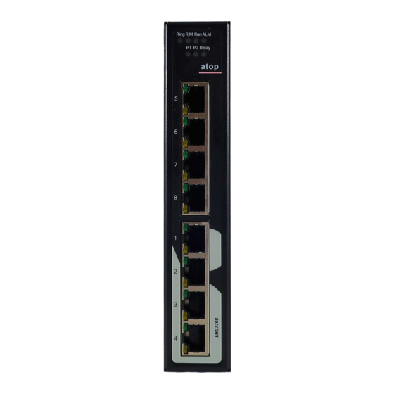
Industrial Managed Ethernet User Manual Switch – EHG77XX 3.2.1 State The PortsState Webpage shown in Figure 3.13 for EHG7711 and Figure 3.14 for EHG7708 provide overview states of the managed switch’s ports. The port states are typically illustrated as summarized in Table 3.7. Note that there are different images for RJ45 and SFP ports. -
Page 185: Traffic Overview
Industrial Managed Ethernet User Manual Switch – EHG77XX The user can check the Auto-refresh box to refresh the page automatically. Note that automatic refresh occurs every 3 seconds. Otherwise, the user can click Refresh button to refresh the page immediately. 3.2.2 Traffic Overview This Traffic Overview Webpage provides an overview of general traffic statistics for all ports of managed switch as... -
Page 186: Qcl Status
Industrial Managed Ethernet User Manual Switch – EHG77XX Figure 3.16 Queuing Counters (QoS Statistics) Webpage Table 3.9 Descriptions of Queuing Counters (QoS Statistics) Label Description Port The logical port for the settings contained in the same row. There are 8 QoS queues per port. Q0 is the lowest priority queue. Rx/Tx The number of received and transmitted packets per queue. -
Page 187: Detailed Statistics
Industrial Managed Ethernet User Manual Switch – EHG77XX Any: Match any frame type. Ethernet: Match EtherType frames. LLC: Match (LLC) frames. SNAP: Match (SNAP) frames. IPv4: Match IPv4 frames. IPv6: Match IPv6 frames. Action Indicates the classification action taken on ingress frame if parameters configured are matched with the frame's content. -
Page 188: Figure 3.18 Detailed Port Statistics Webpage
Industrial Managed Ethernet User Manual Switch – EHG77XX Figure 3.18 Detailed Port Statistics Webpage Table 3.11 Descriptions of Detailed Port Statistics Label Description Receive Total and Transmit Total Rx and Tx Packets The number of received and transmitted (good and bad) packets. Rx and Tx Octets The number of received and transmitted (good and bad) bytes. -
Page 189: Name Map
Industrial Managed Ethernet User Manual Switch – EHG77XX Rx Filtered The number of received frames filtered by the forwarding process. Tx Drops The number of frames dropped due to output buffer congestion. Tx Late/Exc. Coll. The number of frames dropped due to excessive or late collisions. The user can check the Auto-refresh box to refresh the page automatically. -
Page 190: Erps
Industrial Managed Ethernet User Manual Switch – EHG77XX Figure 3.20 Webpage to PoE Status Table 3.12 Descriptions of PoE Status Label Description Port The port number that supports PoE function Enable State Enable or Disable of PoE function. Power Status The status will be On when there is a power device (PD) on the other end or Off when there is no PD on the other end. - Page 191 Industrial Managed Ethernet User Manual Switch – EHG77XX TxRapsActive Specifies whether we are currently supposed to be transmitting R-APS PDUs on our ring ports. cFOPTo Failure of Protocol - R-APS Rx Time Out. Tx Info UpdateTimeSecs Time in seconds since boot that this structure was last updated. Request Request/state according to G.8032, table 10-3.
-
Page 192: Figure 3.22 Erps Detailed Status Webpage
Industrial Managed Ethernet User Manual Switch – EHG77XX Figure 3.22 ERPS Detailed Status Webpage Table 3.14 Description of ERPS Detailed Status Label Description Configuration This table shows the current configuration for this ERPS instance. Go to the ERPS Configuration help page for further explanation. Status This shows the current status of the ERPS instance. -
Page 193: Dhcpv4
Industrial Managed Ethernet User Manual Switch – EHG77XX Label Description Manual switch to Port1: Causes a switchover if the signal is good and no forced switch is in effect. Blocks port0 and unblocks port1. 3.5 DHCPv4 3.5.1 Snooping Table This DHCPv4 Snooping Table Webpage shown in Figure 3.23 displays the dynamic IP assigned information after DHCP Snooping mode is disabled. -
Page 194: Relay Statistics
Industrial Managed Ethernet User Manual Switch – EHG77XX 3.5.2 Relay Statistics This Webpage provides statistics for DHCP Relay as shown in Figure 3.24. The DHCP Relay Statistics are divided into Server Statistics and Client Statistics. Description of each DHCP Relay Statistics is summarized in Table 3.16. -
Page 195: Security
Industrial Managed Ethernet User Manual Switch – EHG77XX also determines which port’s detailed statistics will be or Relay. Next, the port drop-down selection box display on the Webpage. The user can check the Auto-refresh box to refresh the page automatically. Note that automatic refresh occurs every 3 seconds. -
Page 196: Network
Industrial Managed Ethernet User Manual Switch – EHG77XX Figure 3.26 Security Menu Group under Monitor 3.6.1 Network 3.6.1.1 Port Security Overview This webpage in Figure 3.27 shows the Port Security status. Port Security is a module with no direct configuration. Configuration comes indirectly from other modules - the user modules. -
Page 197: Table 3.18 Descriptions Of Port Security Switch Status Webpage
Industrial Managed Ethernet User Manual Switch – EHG77XX Table 3.18 Descriptions of Port Security Switch Status Webpage Label Description User Module Legend User Module The full name of a module that may request Port Security services. Name Abbr A one-letter abbreviation of the user module. This is used in the Users column in the port status table. -
Page 198: Figure 3.28 Details Of Port Security Port Status All Ports Webpage
Industrial Managed Ethernet User Manual Switch – EHG77XX Figure 3.28 Details of Port Security Port Status All Ports Webpage Table 3.19 Descriptions of Port Security Port Status All Ports Webpage Label Description Delete Click to remove this entry of MAC addresses from MAC address table. The button is only clickable if the entry type is Dynamic. -
Page 199: Figure 3.29 Network Access Server Switch Status Webpage
Industrial Managed Ethernet User Manual Switch – EHG77XX Figure 3.29 Network Access Server Switch Status Webpage Table 3.20 Descriptions of Network Access Server Switch Status Webpage Label Description The switch’s port number. Click to navigate to detailed NAS statistics for this port. Port Admin State The port's current administrative state. -
Page 200: Figure 3.30 Nas Statistics Port 1 Webpage
Industrial Managed Ethernet User Manual Switch – EHG77XX Figure 3.30 NAS Statistics Port 1 Webpage Table 3.21 Descriptions of NAS Statistics Port 1 Webpage Label Description Port State Admin State The port's current administrative state. Refer to NAS Admin State for a description of possible values. -
Page 201: Figure 3.31 Acl Status Webpage
Industrial Managed Ethernet User Manual Switch – EHG77XX State The client can either be authenticated or unauthenticated. In the authenticated state, it is allowed to forward frames on the port, and in the unauthenticated state, it is blocked. As long as the backend server hasn't successfully authenticated the client, it is unauthenticated. -
Page 202: Figure 3.32 Dynamic Arp Inspection Table Webpage
Industrial Managed Ethernet User Manual Switch – EHG77XX Rate Limiter Indicates the rate limiter number of the ACE. The allowed range is 1 to 16. When Disabled is displayed, the rate limiter operation is disabled. Forward packet that matched the specific ACE to CPU. Counter The counter indicates the number of times the ACE was hit by a frame. -
Page 203: Figure 3.33 Dynamic Ip Source Guard Table Webpage
Industrial Managed Ethernet User Manual Switch – EHG77XX Table 3.23 Descriptions of Dynamic ARP Inspection Table Label Description Switch’s Port Number in which the entries are displayed. Port VLAN ID VLAN ID in which the ARP traffic is permitted. User’s MAC address of the entry. MAC Address User’s IP address of the entry. -
Page 204: Aaa
Industrial Managed Ethernet User Manual Switch – EHG77XX 3.6.2 3.6.2.1 RADIUS Overview The user can check the status of RADIUS server as shown in Figure 3.34. Note that RADIUS servers can be configured in the RADIUS Server Configuration Webpage. In this RADIUS Overview Webpage, the table lists the RADIUS server by its number from 1 to 5. -
Page 205: Figure 3.35 Radius Authentication Statistics For Server #1 Webpage
Industrial Managed Ethernet User Manual Switch – EHG77XX Figure 3.35 RADIUS Authentication Statistics for Server #1 Webpage Table 3.26 Descriptions of RADIUS Authentication Statistics for Server #1 Label Description RADIUS Authentication Statistics for Server#1 RADIUS Authentication Statistics map closely to those specified in RFC4668 - RADIUS Authentication Client MIB. -
Page 206: Figure 3.36 Radius Authentication And Accounting Statistics Webpage
Industrial Managed Ethernet User Manual Switch – EHG77XX counted as a retransmit as well as a timeout. A send to a different server is counted as a Request as well as a timeout. Other Info IP Address IP address and UDP port for the authentication server in question. -
Page 207: Table 3.27 Descriptions Of Radius Authentication Statistics Webpage
Industrial Managed Ethernet User Manual Switch – EHG77XX Table 3.27 Descriptions of RADIUS Authentication Statistics Webpage Label Description RADIUS Authentication Statistics for Server#1 RADIUS Authentication Statistics map closely to those specified in RFC4668 – RADIUS Authentication Client MIB. Use the server select box to switch between the backend servers to show details for. -
Page 208: Switch
Industrial Managed Ethernet User Manual Switch – EHG77XX before this occurs is displayed in parentheses. This state is only reachable when more than one server is enabled. Round-Trip Time The time interval (measured in milliseconds) between the most recent Access-Reply/Access-Challenge and the Access- Request that matched it from the RADIUS authentication server. -
Page 209: Table 3.28 Descriptions Of Rmon Statistics Status Overview
Industrial Managed Ethernet User Manual Switch – EHG77XX Table 3.28 Descriptions of RMON Statistics Status Overview Label Description Indicates the index of statistics entry. Data The port ID which wants to be monitored. Source(ifIndex) Drop The total number of events in which packets were dropped by the probe due to lack of resources. -
Page 210: Figure 3.39 Rmon History Overview Webpage
Industrial Managed Ethernet User Manual Switch – EHG77XX Figure 3.39 RMON History Overview Webpage Table 3.29 Descriptions of RMON History Overview Label Description History Index Indicates the index of History control entry. Sample Index Indicates the index of the data entry associated with the control entry. Sample Start The value of sysUpTime at the start of the interval over which this sample was measured. -
Page 211: Figure 3.40 Rmon Alarm Overview Webpage
Industrial Managed Ethernet User Manual Switch – EHG77XX will use the last entry of the currently displayed table as a basis for the next lookup. When the end is reached, the text "No more entries" is shown in the displayed table. The user can click on the button to start over and display the first entry in the RMON Alarm table. -
Page 212: Figure 3.41 Rmon Event Overview Webpage
Industrial Managed Ethernet User Manual Switch – EHG77XX Rising Trigger alarm when the first value is larger than the rising threshold. Falling Trigger alarm when the first value is less than the falling threshold. RisingOrFalling Trigger alarm when the first value is larger than the rising threshold or less than the falling threshold (default). -
Page 213: Aggregation
Industrial Managed Ethernet User Manual Switch – EHG77XX 3.7 Aggregation 3.7.1 Status To check the status of ports in Aggregation group, the user can monitor them in this Webpage. Note that using multiple ports in parallel can increase the link speed beyond the limits of a single port and can increase redundancy for higher availability in data communications. -
Page 214: Figure 3.44 Lacp System Status Webpage
Industrial Managed Ethernet User Manual Switch – EHG77XX 3.7.2.1 System Status A status overview for all LACP instances is shown in this Webpage. The LACP or Link Aggregation Control Protocol is an IEEE 802.3ad standard protocol. This protocol allows bundling of several physical ports together to form a single logical port. -
Page 215: Figure 3.45 Lacp Internal Port Status Webpage
Industrial Managed Ethernet User Manual Switch – EHG77XX Figure 3.45 LACP Internal Port Status Webpage Table 3.34 Descriptions of LACP Internal Port Status Webpage Label Description The switch’s port number. Port The current port’s state: State Down: The port is not active. ... -
Page 216: Figure 3.47 Lacp Statistics Webpage
Industrial Managed Ethernet User Manual Switch – EHG77XX Table 3.35 Monitoring Descriptions of LACP Neighbour Port Status Label Description The switch’s port number. Port The current port’s state: State Down: The port is not active. Active: The port is in active state. ... -
Page 217: Spanning Tree
Industrial Managed Ethernet User Manual Switch – EHG77XX Table 3.36 Descriptions of LACP Statistics Webpage Label Description The switch’s port number. Port LACP Received Shows how many LACP frames have been received at each port. LACP Transmitted Shows how many LACP frames have been sent from each port. Discarded Shows how many unknown or illegal LACP frames have been discarded at each port. -
Page 218: Port Statistics
Industrial Managed Ethernet User Manual Switch – EHG77XX Figure 3.49 STP Port Status Webpage Table 3.38 Descriptions of STP Port Status Webpage Label Description The managed switch’s port number of the logical STP port. Port CIST Role The current STP port role of the CIST port. The port role can be one of the following values: AlternatePort, BackupPort, RootPort, DesignatedPort, or Disabled. -
Page 219: Ipmc
Industrial Managed Ethernet User Manual Switch – EHG77XX Table 3.39 Descriptions of STP Statistics Webpage Label Description The managed switch’s port number of the logical STP port. Port Transmitted/Received MSTP The number of MSTP (Multiple Spanning Tree Protocol) BPDU's received/transmitted on the port. Transmitted/Received RSTP The number of RSTP (Rapid Spanning Tree Protocol) BPDU's received/transmitted on the port. -
Page 220: Figure 3.53 Igmp Snooping Status Webpage
Industrial Managed Ethernet User Manual Switch – EHG77XX Figure 3.53 IGMP Snooping Status Webpage Table 3.40 Descriptions of DHCP Server Statistics Monitoring Label Description Statistics VLAN ID The VLAN ID of the entry. Querier Version The currently working Querier Version. Host Version The currently working Host Version. -
Page 221: Figure 3.54 Igmp Snooping Group Information Webpage
Industrial Managed Ethernet User Manual Switch – EHG77XX to select the starting point in the IGMP Group Table. Clicking the Refresh button will update the displayed table starting from that entered VLAN ID and the group address found in the IGMP Group Table or the closest match in IGMP Group Table. -
Page 222: Mld Snooping
Industrial Managed Ethernet User Manual Switch – EHG77XX text "No more entries" is shown in the displayed table. The user can click on the button to start over and display the first entry in the IGMP SFM Information Table. Table 3.42 summarizes the descriptions of labels on the IGMP SFM Information Table. -
Page 223: Figure 3.56 Mld Snooping Status Webpage
Industrial Managed Ethernet User Manual Switch – EHG77XX Figure 3.56 MLD Snooping Status Webpage Table 3.43 Descriptions of Labels on MLD Snooping Status Webpage Label Description VLAN ID The VLAN ID of the entry. Querier Version Current working querier version. Host Version Current working host version. -
Page 224: Figure 3.57 Mld Snooping Group Information Webpage
Industrial Managed Ethernet User Manual Switch – EHG77XX MLD Group Table. In addition, the two input fields will assume the value of the first displayed entry after the Refresh button is clicked. This allows the user to continuously refresh the table with the updated starting address. The user can check the Auto-refresh box to refresh the page automatically. -
Page 225: Lldp
Industrial Managed Ethernet User Manual Switch – EHG77XX The user can check the Auto-refresh box to refresh the page automatically. Note that automatic refresh occurs every 3 seconds. Otherwise, the user can click Refresh button to refresh this page immediately. The button will use the last entry of the currently displayed table as a basis for the next lookup. -
Page 226: Port Statistics
Industrial Managed Ethernet User Manual Switch – EHG77XX Figure 3.59 LLDP Neighbour Information Webpage Table 3.46 Descriptions of LLDP Neighbour Information Label Description Local Interface The interface on which the LLDP frame was received. The identification of the neighbour’s LLDP frames. Chassis ID Port ID The identification of the neighbour port. -
Page 227: Figure 3.60 Lldp Global Couters And Statistics Local Counters Webpage
Industrial Managed Ethernet User Manual Switch – EHG77XX Figure 3.60 LLDP Global Couters and Statistics Local Counters Webpage Table 3.47 Monitoring Descriptions of LLDP Global and Statistics Local Counters Label Description LLDP Global Counters Clear global counters If checked the global counters are cleared when Clear button is pressed. -
Page 228: Ptp
Industrial Managed Ethernet User Manual Switch – EHG77XX Org. Discarded If LLDP frame is received with an organizationally TLV, but the TLV is not supported, the TLV is discarded and counted. Age-Outs Each LLDP frame contains information about how long the LLDP information is valid (age out time). -
Page 229: As Statistics
Industrial Managed Ethernet User Manual Switch – EHG77XX 3. E2e Transp - Clock's device type is end-to-end transparent clock. 4. Master Only - Clock's device type is master only. 5. Slave Only - Clock's device type is slave only. Port List Shows the ports configured for that clock Instance. -
Page 230: Mac Table
Industrial Managed Ethernet User Manual Switch – EHG77XX announceReceiptTimeoutCount A counter that increases every time when announce receipt timeout occurs. pdelayAllowedLostResponsesExceededCount A counter that increases everytime the value of the variable lostResponses exceeds the value of the variable allowedLostResponses. 3.12 MAC Table MAC table is a table that is automatically filled by the EHG77XX managed switch. -
Page 231: Vlans
Industrial Managed Ethernet User Manual Switch – EHG77XX MAC address The MAC address of the entry. Port Members The ports that are members of the entry. 3.13 VLANs 3.13.1 Membership This page as shown in Figure 3.64 provides an overview of membership status of VLAN (Virtual Local Area Network) users. -
Page 232: Ports
Industrial Managed Ethernet User Manual Switch – EHG77XX Port Members A row of check boxes for each port is displayed for each VLAN ID. If a port is included in a VLAN, the following image will be displayed: . If a port is in the forbidden port list, the following image will be displayed: . -
Page 233: Ddmi
Industrial Managed Ethernet User Manual Switch – EHG77XX Port VLAN ID Shows the Port VLAN ID (PVID) that a given user wants the port to have. The field is empty if it is not overridden by the selected user. Tx Tag Shows the Tx Tag requirements (Tag All, Tag PVID, Tag UVID, Untag All, Untag PVID, Untag UVID) that a given user has on a port. -
Page 234: Detailed
Industrial Managed Ethernet User Manual Switch – EHG77XX Revision Indicates revision level for part number provided by SFP vendor. Data Code Indicates vendor's manufacturing date code. Transceiver Indicates transceiver compatibility. 3.14.2 Detailed The detailed DDMI information are displayed on this webpage as shown in Figure 3.67. Detailed information of only one port is showed at a time. -
Page 235: Udld
Industrial Managed Ethernet User Manual Switch – EHG77XX Low Alarm Threshold The low alarm threshold value of temperature, voltage, Tx bias, Tx power, and Rx power. High Alarm Threshold The high alarm threshold value of temperature, voltage, Tx bias, Tx power, and Rx power. -
Page 236: Sd Status
Industrial Managed Ethernet User Manual Switch – EHG77XX 3.16 SD Status The EHG77XX managed switch supports an external memory storage in a form of SD card. An SD card slot can be located on the back of the managed switch chasis under the DIN rail clip. Note that the supported format of the file system on the SD card are FAT32 and exFAT. -
Page 237: Diagnostics
Figure 4.1 Diagnostics Menu 4.1 Ping (IPv4) Atop’s managed switch provides a network tool called Ping for testing network connectivity in this subsection. Ping is a network diagnostic utility for testing reachability between a destination device and the managed switch. It utilizes ICMP (Internet Control Message Protocol) packet to troubleshoot IP connectivity issues. - Page 238 Industrial Managed Ethernet User Manual Switch – EHG77XX Label Description Payload Size Determines the size of the ICMP data payload in bytes (excluding the size of Ethernet, IP and ICMP headers). The default value is 56 bytes. The valid range is 2-1452 bytes.
-
Page 239: Ping (Ipv6)
Industrial Managed Ethernet User Manual Switch – EHG77XX Figure 4.3 Result of successful IPv4 ping Figure 4.4 Result of failed IPv4 ping 4.2 Ping (IPv6) This page allows you to issue ICMPv6 PING packets to troubleshoot IPv6 connectivity issues. The user can enter an IP address or a domain name into the Hostname or IP Address field to verify network connectivity for IP version 6 network as shown in Figure 4.5. -
Page 240: Figure 4.6 Result Of Successful Ipv6 Ping
Industrial Managed Ethernet User Manual Switch – EHG77XX Figure 4.6 Result of successful IPv6 ping Figure 4.7 Result of failure IPv6 ping Table 4.2 Descriptions of Options for Ping (IPv6) Diagnostic Tool Label Description Hostname or IP Address The address of the destination host, either as a symbolic hostname or an IP Address. -
Page 241: Traceroute (Ipv4)
Industrial Managed Ethernet User Manual Switch – EHG77XX Label Description Checking this option will enable the quiet mode which only print the ping’s final Quiet (only print result) results without the result of each ping request. 4.3 Traceroute (IPv4) Traceroute (IPv4) is another diagnostic tool that allows the user to check the path or route that packets take from the managed switch to a destination host or IP address. -
Page 242: Traceroute (Ipv6)
Industrial Managed Ethernet User Manual Switch – EHG77XX Label Description must be configured on a local interface. Leave this field empty for automatic selection based on routing configuration. Note: You may only specify either the VID or the IP Address for the source interface. - Page 243 Industrial Managed Ethernet User Manual Switch – EHG77XX Label Description Response Timeout Specifies the timeout for the response message or ICMP echo reply after an ICMP echo request message is sent to an intermediate host or gateway. Determines the number of seconds to wait for a reply to a sent request. The default number is 3.
-
Page 244: Maintenance
Industrial Managed Ethernet User Manual Switch – EHG77XX 5 Maintenance Maintenance menu is the last main menu on the WebUI on the EHG77XX Industrial Managed Ethernet Switch. Figure 5.1 shows all submenus under the Maintenance menu. Under this menu, the user can restart the device through the WebUI, reset the configuration of the device to the original factory default settings, upload new firmware image to update the device, and manage the configuration of the device. -
Page 245: Factory Defaults
Industrial Managed Ethernet User Manual Switch – EHG77XX Figure 5.3 System Restart in Progress Webpage 5.2 Factory Defaults When the managed switch is not working properly, the user can reset it back to the original factory default settings by selecting MaintenanceFactory Defaults menu. Note that the IP configuration will not be changed after using this menu. -
Page 246: Software
The users can update the device firmware via web interface using Upload menu as shown in Figure 5.6. To update the firmware, the users can download a new firmware from Atop’s website and save it on a local computer. Then, the users can click Select File…... -
Page 247: Save Startup-Config
Industrial Managed Ethernet User Manual Switch – EHG77XX The Configuration menu enables the user to manage the configuration file on the switch. Under the MaintenanceConfiguration menu, there are Save startup-config, Download, Upload, Activate, and Delete submenus as shown in Figure 5.7. Figure 5.7 Submenus under MaintenanceConfiguration menu 5.4.1 Save startup-config... -
Page 248: Upload
Industrial Managed Ethernet User Manual Switch – EHG77XX Figure 5.10 Webpage for Downloading the Current Configuration File 5.4.3 Upload On this Webpage, the user can upload a local configuration file on the user’s computer to the managed switch using web browser. This will be useful when the user would like to use a backup configuration file from another managed switch. -
Page 249: Activate
Industrial Managed Ethernet User Manual Switch – EHG77XX 5.4.4 Activate The user can activate different configuration file inside the managed switch, except for running-config which represents the currently active configuration. The ConfigurationActivate submenu under the Maintenance menu as shown in Figure 5.12 can be used to perform this task. The user can select a configuration file from the list under the File Name table by checking on the radio button in front of that file name. -
Page 250: Figure 5.14 Webpage For Deleting A Configuration File
Industrial Managed Ethernet User Manual Switch – EHG77XX will be presented on the webpage such as “startup-config successfully deleted”. Note that if this is done and the switch is rebooted without a prior Save operation, this effectively resets the switch to default configuration. Figure 5.14 Webpage for Deleting a Configuration File Figure 5.15 Confirmation for deleting a configuration file. - Page 251 Industrial Managed Ethernet User Manual Switch – EHG77XX Atop Technologies, Inc. www.atoponline.com TAIWAN HEADQUARTER and ATOP CHINA BRANCH: INTERNATIONAL SALES: 2F, No. 146, Sec. 1, Tung-Hsing Rd, 3F, 75 , No. 1066 Building, 30261 Chupei City, Hsinchu County Qingzhou North Road, Taiwan, R.O.C.
Need help?
Do you have a question about the EHG7704 Series and is the answer not in the manual?
Questions and answers