Table of Contents
Advertisement
Quick Links
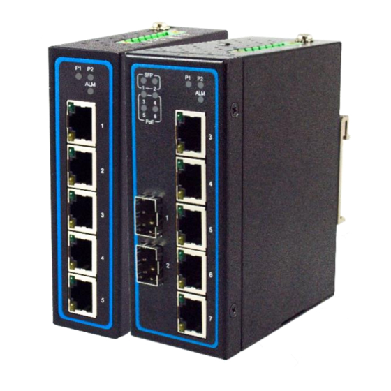
Industrial Unmanaged Gigabit Ethernet Switch
EHG7305 / EHG7306 / EHG7307 Series
Version 1.0
Updated in December, 2015
P/N:89900487G
Package Check List
Inside the package you will find the following items:
■ Industrial Unmanaged Ethernet Switch x 1
■ 7-Pin 5.08mm Lockable Terminal Block (Already mounted to the device) x 1
■ DIN-Rail Kit (Already mounted to the device) x 1
■ Protective caps for all SFP and PoE ports (Depend on purchased model)
■ Installation Guide with Warranty Card x 1
Never install or work on electrical or cabling during periods of lighting activity.
Never connect or disconnect power when hazardous gases are present.
Warning: Hot Surface Do Not Touch. RESTRICTED ACCESS AREA: The equipment
should only be installed in a Restricted Access Area.
Caution: CLASS 1 LASER PRODUCT. Do not stare into the laser!
Product Layout
Front View
EHG7305
EHG7305-4PoE
EHG7306
EHG7307
1 2
1 2
1 2
P1
P2
P1
P2
SFP
P1
P2
SFP
4
ALM
ALM
1
ALM
1
3
3
3
1
2
2
3
3
5
5
3
4
4
5
5
PoE
PoE
PoE
1
1
2
2
2
3
8
6
6
6
3
3
4
4
4
1
5
7
7
5
5
6
1. PWR1 LED
4. SFP Ports LEDs
6. 10/100/1000 BASE-X Ports
2. PWR2 LED
5. PoE LEDs
and/or 10/100/1000 BASE-X PoE Ports
3. Alarm LED
7. 100/1000 BASE-F(X) SFP Slot
8. 1000 BASE-X SFP Slot
Top View
EHG7305
EHG7305-4PoE
EHG7306/EHG7307
1
1
V2+
V2+
2
2
V2–
V2–
3
3
100Mbps
Relay
Relay
6
V1+
V1+
1Gbps
4
4
V1–
V1–
5
5
F.G.
F.G.
1. Grounding Screw
4. Terminal for Power 1
2. Terminal for Power 2
5. Frame Ground
3. Relay Output with current carrying capacity of
6. DIP Switch for SFP
0.5A@24 VDC (Normal Open)
speed selection
Installation Overview
The device's appearance is as in the figure below.
1. If you have purchased the wall mount kit,
proceed to place the screws on the back of the
device as shown in (Fig. 1)
2. Although internal grounding has been done
inside, in order to ensure overall maximum
performance and protect your device it is still
strongly advised to ground the device properly;
hazardous ESD can come into contact with it and
damage your equipment. On the power terminal block, there is a terminal for
Frame Ground, you can choose whether to connect it to the grounding or you may
opt to connect to the grounding screw next to the terminal block (the one chosen
should be connected at all times) (Fig. 2~4).
1 2
P1
P2
4
V2+
V2+
2
ALM
3
V2–
V2–
4
5
Relay
Relay
6
V1+
V1+
3
V1–
V1–
F.G.
F.G.
4
6
1
5
(Fig. 2)
(Fig. 3)
2
6
3. You can then choose whether to plug in the I/O ports at this point or do it later
depending on the actual location of the device or level of comfort for performing
7
such operation. Remember to plug in the protective caps for the unused SFP
and PoE ports.
4. Once the plate has been firmly put in place,
proceed to mount the whole device as shown
in (Fig. 5).
Proceed to (Fig. 6) if you want to remove the
device from DIN-Rail.
5. Next we can then proceed to connect the
1
device to the LAN (switch or PC, depending on
the case), take care on using the RJ-45
2
V2+
connector; after this we can then proceed to
V2–
3
Relay
the device's settings.
4
V1+
5
V1–
F.G.
(Fig. 1)
(Fig. 7)
(Fig. 8)
LED Indicators
Name
Color
Status
P1
On
Power is being supplied through this power input
Green
V2+
V2–
P2
Off
Power is not supplied through this power input
Relay
V1+
On
Power is only supplied through PWR1 or PWR2
V1–
F.G.
ALM
Red
Off
Power is supplied through PWR1 and PWR2
Off
or device is not powered on
(Fig. 4)
On
Port is linked
SFP
Green
Blinking
Data is transmitting on this port
Off
No data is transmitting on this port
On
Power is being supplied to a Powered Device (PD)
PoE
Amber
1
Off
Power is not supplied to a PD
On
Ethernet is connected at 10/100Mbps
Amber
Blinking
Data is transmitting on this port
Off
Ethernet is disconnected
LAN
On
Ethernet is connected at 1Gbps
Green
Blinking
Data is transmitting on this port
2
(Fig. 5)
Off
Ethernet is disconnected
1
Attention
1. It is recommend to use at least 20 AWG cable and the cable needs to be resistant
to at least 85°C on the power connector.
2. Torque applied to the Terminal block's screw should be 4.5 in. lb (0.51 Nm)
3. The device needs to be installed inside a Type 1 housing.
2
(Fig. 6)
■ The opening to the sides are for the device's
heat dissipation please never obstruct or cover
them with any objects or try to insert them
through it. (Fig. 2~4 & Fig. 7~8)
Message
Advertisement
Table of Contents

Related Manuals for Atop EHG7305 Series


Summary of Contents for Atop EHG7305 Series
- Page 1 Package Check List Installation Overview ■ The opening to the sides are for the device’s The device’s appearance is as in the figure below. Inside the package you will find the following items: 1. If you have purchased the wall mount kit, heat dissipation please never obstruct or cover ■...
- Page 2 31.5 cost from the customer to Atop will be reimbursed by Atop. Power Requirements After 3 months and still within the warranty period, it is up to Atop whether to Bottom View Top View replace the unit with a new one; normally, as long as a product is under warranty,...
Need help?
Do you have a question about the EHG7305 Series and is the answer not in the manual?
Questions and answers