Table of Contents
Advertisement
Quick Links
Unmanaged Fast Ethernet Switch
EH3305 / EH3005 Series
Version 1.0
Updated in December, 2020
P/N : 89900594G
Package Check List
Inside the package you will find the following items:
■ Industrial Unmanaged Ethernet Switch x 1
■ 5-Pin 5.08mm Lockable Terminal Block (Already mounted to the device) x 1
■ DIN-Rail Kit (Already mounted to the device) x 1
■ Installation Guide with Warranty Card x 1
Never install or work on electrical or cabling during periods of lighting activity.
Never connect or disconnect power when hazardous gases are present.
Warning: Hot Surface Do Not Touch. RESTRICTED ACCESS AREA: The equipment
should only be installed in a Restricted Access Area.
Product Technical Specification
1. Power input: 12-48VDC, 0.5A max.
2. Operating Temperature:
■ EH3305: -40 to 70° C (-40° F to 158° F)
■ EH3005: 0 to 60 ° C (32° F to 140° F)
3. Storage Temperature:
■ EH3305: -40 to 85°C (-40°F to 185°F)
■ EH3005: -20 to 70°C (-4°F to 158°F)
4. Ambient Relative Humidity: 5 to 95%, 55°C (non-condensing)
5. EH3305: IP30 protection
6. EH3005: IP40 protection
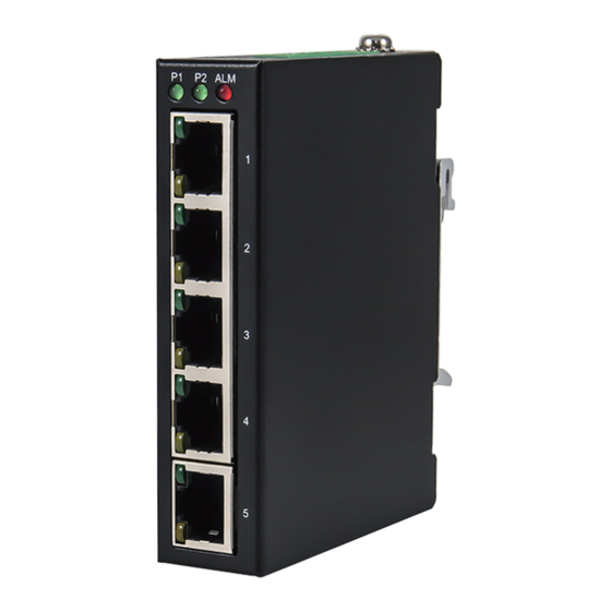
Product Layout
Front View
EH3005
EH3305
EH3005
1 2
1 2
P1
P2 ALM
P1
P1
P2 ALM
P2 ALM
3
3
1
1
2
2
4
3
3
4
4
4
5
5
5
1. P1 LED
5. Terminal for P2
2. P2 LED
6. Terminal for P1
3. Alarm LED
7. Functional Ground
4. 10/100 BASE-T(X) Ports
8. Grounding Screw
Installation Overview
The device's appearance is as in the figure below.
1. If you have purchased the wall mount
kit, proceed to place the screws on the
back of the device as shown in (Fig. 1)
2. Although internal grounding has been
done inside, in order to ensure overall
maximum performance and protect your
device it is still strongly advised to ground
the device properly; hazardous ESD can
come into contact with it and damage
your equipment. On the power terminal
block, there is a terminal for Frame
Ground, you can choose whether to
connect it to the grounding or you may opt
to connect to the grounding screw next to
the terminal block (the one chosen should
be connected at all times) (Fig. 2~3).
3. You can then choose whether to plug in
the I/O ports at this point or do it later
depending on the actual location of the
device or level of comfort for performing
such operation. Remember to plug in the
protective caps for the unused SFP and
PoE ports.
4. Wall mount Screw spec. : M3
Screw depth : 4.0 mm(Max)
Screw : 4 PCS
Top View
5. Once the plate has been firmly put in
EH3305
place, proceed to mount the whole device
as shown in (Fig. 4).
Proceed to (Fig. 5) if you want to remove
the device from DIN-Rail.
8
6. Next we can then proceed to connect
the device to the LAN (switch or PC,
V2+
V2+
depending on the case), take care on
5
5
V2
V2
using the RJ-45 connector; after this we
V1+
V1+
6
6
V1
V1
can then proceed to the device's settings.
7
7
F.G.
F.G.
7. Din Rail screw
Screw spec. : M4
Screw depth: 6.0mm(Max.)
Screw : 3 pcs
■ The opening to the sides are for the
device's heat dissipation please never
obstruct or cover them with any objects or
try to insert them through it. Please keep
minimum 5 CM distance with others
device. (Fig. 2~3 & Fig. 6~7)
(Fig. 1)
V2+
V2+
V2
V2
V1+
V1+
V1
V1
F.G.
F.G.
(Fig. 2)
(Fig. 3)
1
2
(Fig. 4)
1
2
(Fig. 5)
(Fig. 6)
(Fig. 7)
Advertisement
Table of Contents

Related Manuals for Atop EH3305 Series


Summary of Contents for Atop EH3305 Series
- Page 1 Package Check List Installation Overview Inside the package you will find the following items: The device’s appearance is as in the figure below. ■ Industrial Unmanaged Ethernet Switch x 1 1. If you have purchased the wall mount ■ 5-Pin 5.08mm Lockable Terminal Block (Already mounted to the device) x 1 kit, proceed to place the screws on the ■...
- Page 2 3 months after purchase. The shipping cost from the customer to Atop will be reimbursed by Atop. EH3005 Ethernet is not linked After 3 months and still within the warranty period, it is up to Atop whether to Front View Side View Rear View replace the unit with a new one;...
Need help?
Do you have a question about the EH3305 Series and is the answer not in the manual?
Questions and answers