Table of Contents
Advertisement
Quick Links
Industrial Managed Gigabit Ethernet Switches
EHG7504/EHG7508 Series
EHG7604/EHG7608 Series
Version 1.2
Updated in November, 2016
P/N:89900488G
Inside the package you will find the following items:
■ Industrial Managed Gigabit Ethernet Switch x 1
■ 4-Pin 5.08mm Lockable Terminal Block (Already mounted to the device) x 1
■ 5-Pin 5.08mm Lockable Terminal Block (Already mounted to the device) x 1
■ DIN-Rail Kit (Already mounted to the device) x 1
■ Protective caps for all SFP and PoE ports (Depend on purchased model)
■ Installation Guide with Warranty Card x 1
Never install or work on electrical or cabling during periods of lightning activity.
Never connect or disconnect power when hazardous gases are present.
Warning:Hot Surface Do Not Touch. RESTRICTED ACCESS AREA: The equipment
should only be installed in a Restricted Access Area.
Caution: CLASS 1 LASER PRODUCT. Do not stare into the laser!
This equipment should be installed indoor and not connect directly with equipment
installed outdoor.
I n d o o r
I n d o o r
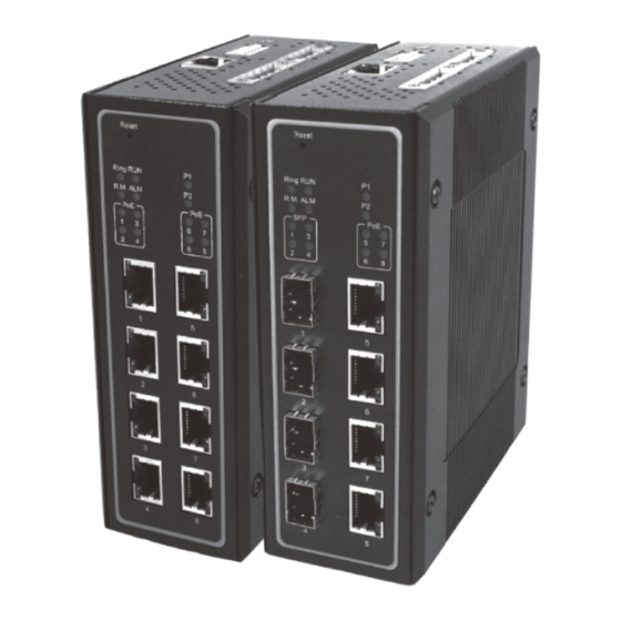
Front View
EHG7504
EHG7504-2SFP
EHG7508
EHG7504-4POE
EHG7504-2POE-2SFP
EHG7504-4SFP
EHG7508-8POE
EHG7604-4SFP
EHG7604
EHG7604-2SFP
EHG7608
EHG7604-4POE
EHG7604-2POE-2SFP
EHG7608-8POE
1
1
1
1
2
3
7
2
3
7
2
3
3
7
2
5
4
5
8
4
5
8
4
5
8
4
9
6
9
6
10
11
11
10
11
1. Reset button
7. PWR1 LED
2. Ring LED
8. PWR2 LED
3. RUN LED
9. PoE LEDs
4. Ring Master LED
10. 1000 BASE-X SFP Slots
5. Alarm LED
11. 10/100/1000 BASE-T(X) RJ-45 Ports and/or
6. SFP Ports LEDs
10/100/1000 BASE-T(X) PoE RJ-45 Ports
1. Grounding Screw
2. DIP Switches
1
3. RS-232 Console
4
4. Relay Output 1 with current carrying
2
5
capacity of 1A@24 VDC (Normal Open)
6
3
5. Relay Output 2 with current carrying
7
capacity of 1A@24 VDC (Normal Open)
8
6. Frame Ground
7. Terminal for Power 1
8. Terminal for Power 2
1.
If you have purchased the wall mount kit,
proceed to place the screws on the back
of the device as show in (Fig. 1).
2. Although internal grounding has been
done inside, in order to ensure overall
maximum performance and protect your
device, it is still strongly advised to ground
the device properly; hazardous ESD can
come into contact and damage your
EHG7508-4SFP
EHG7508-4POE-4SFP
equipment. On the power terminal block,
EHG7608-4SFP
there is a terminal for Frame Ground, you
EHG7608-4POE-4SFP
can choose whether to connect it to the
grounding or you may opt to connect to
1
the grounding screw next to the terminal
7
2
3
7
8
4
5
8
block ( the one chosen should be connect-
9
6
9
ed at all times ) (Fig. 2)
1
10
11
3.
You can then choose whether to plug in the other
peripheral ports at this point or do it later depending
on the actual location of the device or level of
comfort for performing such operation.
Remeber to plug in the protective caps for the
unused SFP and PoE ports.
2
4.
Once the plate has been firmly put in place, proceed
1
to mount the whole device as shown in (Fig.
3).Proceed to (Fig. 4) if you want to remove the
device from DIN-Rail.
5.
Next we can then proceed to connect the device to
the LAN (switch or PC, depending on the case), take
care on using the RJ-45 connector; after this we can
then proceed to the device's settings
2
■ The opening to the sides are for the device's heat
dissipation please never obstruct or cover them
with any objects or try to insert them through it.
■ This switch's factory IP by default is 10.0.50.1 you
can access the device by its Web UI once it is
connected to a physical network (or using
Management Utility, for more information on
Management Utility, please refer to its manual).
Please be aware that the PC needed for this
procedure needs to be in the same
subnet, or
you may refer yourself to the device User's
Manual.
Name
Color
Status
Message
P1
On
Power is being supplied through this power input
Green
P2
Off
Power is not supplied through this power input
Alarm is triggered by user defined events
On
Red
ALM
Off
Alarm is not triggered by user defined events
Blinking
AP firmware is running normally
RUN
Green
System is not ready or halt
On/Off
On
All the Rings are running normally
Ring
Green
Blinking
Ring is in protection state
Off
Ring is disabled
On
The device is a Master of the Ring
R.M.
Green
Off
The device is a Slave of the Ring
On
Port is linked
SFP
Green
Blinking
Data is transmitting on this port
Off
No data is transmitting on this port
On
Power is being supplied to a Powered Device (PD)
Amber
PoE
Off
Power is not supplied to a PD
On
Ethernet is connected at 1000Mbps
Amber
Blinking
Ethernet is connected at 100Mbps
Ethernet is connected at 10Mbps
Off
LAN
On
Ethernet is connected
Green
Blinking
Data is transmitting on this port
Off
Ethernet is disconnected
Advertisement
Table of Contents

Related Manuals for Atop EHG7504 Series


Summary of Contents for Atop EHG7504 Series
- Page 1 ■ The opening to the sides are for the device’s heat dissipation please never obstruct or cover them 1. Grounding Screw Inside the package you will find the following items: with any objects or try to insert them through it. 2.
- Page 2 Atop will be reimbursed by Atop. Apply standard switch settings After 3 months and still within the warranty period, it is up to Atop whether to Reserve for future use replace the unit with a new one; normally, as long as a product is under warranty, *Settings are applied when the device is restored to default.
Need help?
Do you have a question about the EHG7504 Series and is the answer not in the manual?
Questions and answers