Table of Contents
Advertisement
Quick Links
Industrial Managed
Ethernet Switch
This PDF Document contains internal hyperlinks for ease of navigation.
Page 1 of 191
Atop Technologies, Inc
Industrial Managed
Ethernet Switch
User Manual
November 1
Series covered by this manual:
EH75XX*
* The user interface on these products may be slightly different
from the one shown on this user manual
User Manual
.
V1.8
st
, 2020
Advertisement
Table of Contents

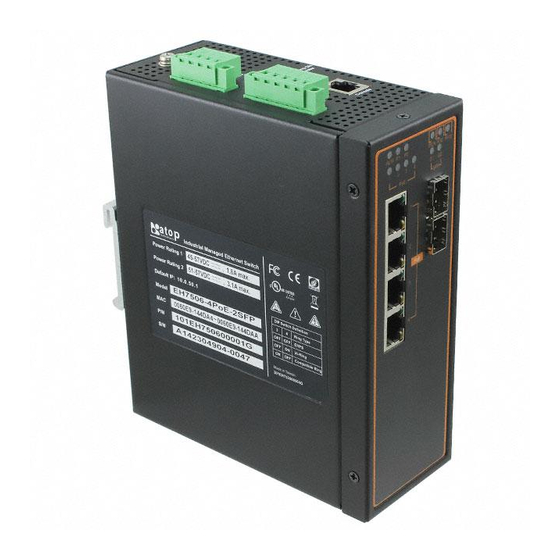
Related Manuals for Atop EH7506-4PoE-2SFP


Summary of Contents for Atop EH7506-4PoE-2SFP
- Page 1 Industrial Managed User Manual Ethernet Switch Atop Technologies, Inc Industrial Managed Ethernet Switch User Manual V1.8 November 1 , 2020 Series covered by this manual: EH75XX* * The user interface on these products may be slightly different from the one shown on this user manual This PDF Document contains internal hyperlinks for ease of navigation.
- Page 2 Ethernet Switch For example, click on any item listed in the Table of Contents to go to that page. Published by: Atop Technologies, Inc. 2F, No. 146, Sec. 1, Tung-Hsing Rd, 30261 Chupei City, Hsinchu County Taiwan, R.O.C. Tel: +886-3-550-8137 Fax: +886-3-550-8131 www.atoponline.com...
- Page 3 Ethernet Switch Important Announcement The information contained in this document is the property of Atop Technologies, Inc., and is supplied for the sole purpose of operation and maintenance of Atop Technologies, Inc., products. No part of this publication is to be used for any other purposes, and it is not to be reproduced, copied, disclosed, transmitted, stored in a retrieval system, or translated into any human or computer language, in any form, by any means, in whole or in part, without the prior explicit written consent of Atop Technologies, Inc.,...
-
Page 4: Table Of Contents
Industrial Managed User Manual Ethernet Switch Table of Contents Introduction ........................12 Introduction to Industrial Managed Switch ..................... 12 Software Features ..........................13 Configuring with a Web Browser ..................14 Web-based Management Basics ......................14 2.1.1 Default Factory Settings ......................... 14 2.1.2 Login Process and Main Window Interface .................... - Page 5 Industrial Managed User Manual Ethernet Switch 2.10 IGMP/IP Multicast ........................... 77 2.10.1 IGMP Settings ............................77 2.10.2 IGMP Statistics ............................79 2.10.3 IGMP IP Multicast Table......................... 82 2.10.4 Static IP Multicast ........................... 83 2.10.5 MLD ................................ 84 2.11 SNMP ..............................88 2.11.1 SNMP ..............................
- Page 6 Industrial Managed User Manual Ethernet Switch Serial Console Setup..........................165 Command Line Interface Introduction ....................166 General Commands ..........................167 Command Example ..........................168 3.4.1 Administration Setup using Serial Console ..................169 3.4.2 Spanning Tree Setup using Serial Console ..................170 Configuring with a Telnet Console .................
- Page 7 Figure 2.62 Mini-GBIC Port Status Webpage ......................58 Figure 2.63 Port Statistics Webpage ........................58 Figure 2.64 Power over Ethernet Dropdown Menu example on EH7506-4PoE-2SFP ........... 59 Figure 2.65 PoE Setting Webpage example on EH7506-4PoE-2SFP ..............60 Figure 2.66 PoE Status Webpage, example on EHG7508-8PoE ................61 Figure 2.67 PoE Alarm Setting ..........................
- Page 8 錯誤! 使用 [常用] 索 引標籤將 Heading Industrial Managed User Manual 1,Product Manual Ethernet Switch 套用到您想要在此處 顯示的文字。 Figure 2.87 IGMP Statistics Webpage ........................79 Figure 2.88 Example of IGMP's Statistics ........................ 80 Figure 2.89 IGMP's IP Multicast Table Webpage ....................82 Figure 2.90 Example of IGMP's IP Multicast Table....................
- Page 9 錯誤! 使用 [常用] 索 引標籤將 Heading Industrial Managed User Manual 1,Product Manual Ethernet Switch 套用到您想要在此處 顯示的文字。 Figure 2.143 ERPS Setting Webpage........................129 Figure 2.144 ERPS RAPS VLAN Setting Webpage ....................130 Figure 2.145 Example of Ring Topology for ERPS Setup (Example made on EH7520) ........131 Figure 2.146 Example of Switch A’s ERPS settings ....................
- Page 10 錯誤! 使用 [常用] 索 引標籤將 Heading Industrial Managed User Manual 1,Product Manual Ethernet Switch 套用到您想要在此處 顯示的文字。 Figure 4.3 Commands in the Privileged Mode ....................... 172 Figure 4.4 Commands in the Configuration Mode ....................173 Figure 5.1 Device Management Utility ........................175 Figure 5.2 Rescan (Search) Icon ...........................
- Page 11 錯誤! 使用 [常用] 索 引標籤將 Heading Industrial Managed User Manual 1,Product Manual Ethernet Switch 套用到您想要在此處 顯示的文字。 Table 2.39 Description of VLAN Setting......................... 103 Table 2.40 Setting Descriptions of 802.1Q VLAN Settings ..................105 Table 2.41 Setting Descriptions of 802.1Q VLAN PVID ..................106 Table 2.42 Descriptions of 802.1Q VLAN Table ....................
-
Page 12: Introduction
Atop’s managed switchisalso an industrial switch and not a commercial switch. A commercial switch simply works in a comfortable office environment. However, an industrial switch is designed to perform in harsh industrial environments, i.e., extreme temperature, high humidity, dusty air, potential high impact, or the presence of... -
Page 13: Software Features
顯示的文字。 1.2 Software Features Atop’s industrialLayer-2 Managed switches come with a wide range of network protocols and software features. These protocols and software features allow the network administrator to implement security and reliability into their network. These features enable Atop’s switches to be usedin safety applications, and factory and process automation. -
Page 14: Configuring With A Web Browser
錯誤! 使用 [常用] 索 引標籤將 Heading Industrial Managed User Manual 1,Product Manual Ethernet Switch 套用到您想要在此處 顯示的文字。 2 Configuring with a Web Browser Chapter 2 explains how to access the industrial managed switchfor the first time. There are three ways to configure this Ethernet Switch: 1. -
Page 15: Login Process And Main Window Interface
錯誤! 使用 [常用] 索 引標籤將 Heading Industrial Managed User Manual 1,Product Manual Ethernet Switch 套用到您想要在此處 顯示的文字。 2.1.2 Login Process and Main Window Interface Before users can access the configuration, they have to log in. This can simply be done in the following steps. Launch a web browser. -
Page 16: Figure 2.3 A Hyperlink To Proceed To The Managed Switch At Ip Address 10.0.50.1
錯誤! 使用 [常用] 索 引標籤將 Heading Industrial Managed User Manual 1,Product Manual Ethernet Switch 套用到您想要在此處 顯示的文字。 Figure 2.3 A hyperlink to proceed to the managed switch at IP address 10.0.50.1 After preceeding through the invalid certificate warning and clicking on the Proceed to 10.0.50.1 (unsafe) hyperlink, a login page will be presented shown in Figure 2.4. -
Page 17: Figure 2.4 Login Page
錯誤! 使用 [常用] 索 引標籤將 Heading Industrial Managed User Manual 1,Product Manual Ethernet Switch 套用到您想要在此處 顯示的文字。 Figure 2.4 Login page For security purpose, if the user did not enter the username and the password within 30 seconds, the login page will time-out and an error notification page will show up. Even though the user entered the correct username and password, the login procedure will not succeed if the login was done more than 30 seconds after the login page was first accessed. -
Page 18: Figure 2.6 Example Of Error Notification On Blocked Account
錯誤! 使用 [常用] 索 引標籤將 Heading Industrial Managed User Manual 1,Product Manual Ethernet Switch 套用到您想要在此處 顯示的文字。 Figure 2.6 Example of error notification on blocked account Note: 1. Any unauthorized login to the managed switch will be recorded to device’s syslog. A pop-up notification is shown in Figure 2.7. -
Page 19: Figure 2.8 Default Web Interface
錯誤! 使用 [常用] 索 引標籤將 Heading Industrial Managed User Manual 1,Product Manual Ethernet Switch 套用到您想要在此處 顯示的文字。 Figure 2.8 Default Web Interface Page 19 of 191... -
Page 20: Basic Information
2.2.1 System Info This subsection provides basic system information of Atop’s industrial managed switch. The user can check the system name, model name, device description, MAC address, firmware version, and memory usage of the switch. Note that Atop’s firmware generally consists of Application version and Kernel version. Figure 2.10 depicts an example of Basic System Information of EHG7506-4PoE-2SFP. -
Page 21: System Setting
2.2.2 System Setting Users can assign device’s details to Atop’s switch in this subsection. By entering unique and relevant system information such as System Name, System Description, System Location, and System Contact, these information can help identify one specific switch among all other devices in the network that supports SNMP. Please click on the “Update”... -
Page 22: Console
錯誤! 使用 [常用] 索 引標籤將 Heading Industrial Managed User Manual 1,Product Manual Ethernet Switch 套用到您想要在此處 顯示的文字。 2.2.3 Console In this chapter, we use a web browser for configuring the switch. However, for the serial console method, please go to Chapter 3 Configuring with Serial Console for more detail on how to connect console to the switch. The Console page here only shows the setting parameters of a serial console’s connection, which can be used by a console software such as Tera Term. -
Page 23: Power Status
2.2.5 Power Status Atop’s managed switch features dual VDC power supply inputs. For Non-PoE models, 9-57VDC can be supplied to Power Input 1 (V1+ and V1- pins) and/or Power Input 2 (V2+ and V2- pins). For PoE models, 45-57VDC should be supplied under 802.3af mode and 51-57VDC should be supplied under 802.3at mode. -
Page 24: Temperature Log
錯誤! 使用 [常用] 索 引標籤將 Heading Industrial Managed User Manual 1,Product Manual Ethernet Switch 套用到您想要在此處 顯示的文字。 Figure 2.14 Power Status Webpage 2.2.6 Temperature Log This subsection provides user and system temperature logs. There are summary statistics and distribution of temperature information for each log. The highest temperature, the lowest temperature and the average temperature are reported in degree Celsius. -
Page 25: Figure 2.15 User Temperature Log
錯誤! 使用 [常用] 索 引標籤將 Heading Industrial Managed User Manual 1,Product Manual Ethernet Switch 套用到您想要在此處 顯示的文字。 Figure 2.15 User Temperature Log Figure 2.16 System Temperature Log Page 25 of 191... -
Page 26: Administration
錯誤! 使用 [常用] 索 引標籤將 Heading Industrial Managed User Manual 1,Product Manual Ethernet Switch 套用到您想要在此處 顯示的文字。 2.3 Administration In this section, users will be able to configure Account, Authentication Server Setting, IP Settings, IPv6 Setting, Ping, Ping6, Mirror Port, System Time, Modbus Setting, PTP, SSH, Telnet, HTTPS, and DIP Switch. Figure 2.17 shows the Administration section with the list of its subsections on the left of the screen. -
Page 27: Figure 2.18 Account Setting Webpage
錯誤! 使用 [常用] 索 引標籤將 Heading Industrial Managed User Manual 1,Product Manual Ethernet Switch 套用到您想要在此處 顯示的文字。 configured through the Password strength configuration box in the last row of Figure 2.18. Note that the users will be reminded during the login procedure with a notification to change their passwords if the passwords have not been changed over the last 30 days. -
Page 28: Auth Server Setting
錯誤! 使用 [常用] 索 引標籤將 Heading Industrial Managed User Manual 1,Product Manual Ethernet Switch 套用到您想要在此處 顯示的文字。 Figure 2.20 Connection Setting Webpage Note that the users will be log out automatically if their sessions or connections are in-active for more than five minutes. -
Page 29: Figure 2.22 Example Of New User Account Setting On Radius Server
錯誤! 使用 [常用] 索 引標籤將 Heading Industrial Managed User Manual 1,Product Manual Ethernet Switch 套用到您想要在此處 顯示的文字。 Shared Key The key used to authenticate with the 12345678 server. Max 15 characters. Re-type the shared key. Max 15 characters. Confirmed Shared Key NULL Authentication Type Authentication mechanism. -
Page 30: Ip Setting
錯誤! 使用 [常用] 索 引標籤將 Heading Industrial Managed User Manual 1,Product Manual Ethernet Switch 套用到您想要在此處 顯示的文字。 2.3.3 IP Setting In this subsection, users may modify network settings of Internet Protocol version 4 (IPv4) for the managed switch, e.g., Static IP Address, Subnet Mask, Gateway, Primary domain name server (DNS), and Secondary DNS. As shown in Figure 2.23, users can choose to Enable Dynamic Host Configuration Protocol (DHCP) Client by checking the box to Obtain an IP Address Automatically. -
Page 31: Ipv6 Setting
2.3.4 IPv6 Setting This subsection enables Atop’s industrial managed switch to operate in Internet Protocol version 6 (IPv6) network. The users have options to enable Autoconfig, DHCPv6, or Manual setting as shown in Figure 2.24. Note that in IPv6 network, there are three types of autoconfiguration: stateless, stateful, and a combination of both. The “Autoconfig”... -
Page 32: Ping
2.3.5 Ping Atop’s managed switch provides a network tool called Ping for testing network connectivity in this subsection. Ping is a network diagnostic utility for testing reachability between a destination device and the managed switch. Note that this utility is only for IPv4 address. The Ping utility for IPv6 will be provided in the next subsection. Figure 2.25 shows the user interface for using the Ping command. -
Page 33: Ping6
錯誤! 使用 [常用] 索 引標籤將 Heading Industrial Managed User Manual 1,Product Manual Ethernet Switch 套用到您想要在此處 顯示的文字。 Figure 2.27 Example of successful ping command result Figure 2.28 Example of unsuccessful ping command result *Note: If users enter a domain name instead of an IP address, they should assign a DNS first. This can be done through Administration ->... -
Page 34: Figure 2.30 Example Of Successful Ping6 Result
錯誤! 使用 [常用] 索 引標籤將 Heading Industrial Managed User Manual 1,Product Manual Ethernet Switch 套用到您想要在此處 顯示的文字。 Figure 2.30 Example of Successful Ping6 Result Page 34 of 191... -
Page 35: Mirror Port
錯誤! 使用 [常用] 索 引標籤將 Heading Industrial Managed User Manual 1,Product Manual Ethernet Switch 套用到您想要在此處 顯示的文字。 2.3.7 Mirror Port In order to help the network administrator keeps track of network activities, the managed switch supports port mirroring, which allows incoming and/or outgoing traffic to be monitored by a single port that is defined as a mirror port. -
Page 36: System Time
2.3.8 System Time Atop’s industrial managed switch has internal calendar (date) and clock (or system time) which can be set manually or automatically. Figure 2.32 shows the System Time and SNTP webpage. The users have options to configure Current Date and Current Time manually. There is a drop-down list of Time Zone which can be selected for the local time zone. -
Page 37: Modbus Setting
2.3.9 Modbus Setting Atop’s managed switch can be connected to a Modbus network using Modbus TCP/IP protocol which is an industrial network protocol for controlling automation equipment. The managed switch’s status and settings can be read and written through Modbus TCP/IP protocol which operates similar to a Management Information Base (MIB) browser. -
Page 38: Figure 2.34 Mapping Table Of Modbus Address For Switch's Ip Address
Ethernet Switch 套用到您想要在此處 顯示的文字。 document. Atop does not provide this software to the users. Tutorial of Modbus read and write examples are illustrated below. Note: The switch only supports Modbus function code 03, 04 )for Read( and 06 )for Write(. -
Page 39: Figure 2.36 Modbus Poll Connection Setup
錯誤! 使用 [常用] 索 引標籤將 Heading Industrial Managed User Manual 1,Product Manual Ethernet Switch 套用到您想要在此處 顯示的文字。 should be set to 502. Then click the OK button. Figure 2.36 Modbus Poll Connection Setup 5. On the window Mbpoll1, select multiple cells from row 0 to row 2 by clicking on cells in second column of row 0 and row 2 while holding the shift key as shown in Figure 2.37. -
Page 40: Figure 2.38 Set Display Mode To Hex In Modbus Poll
錯誤! 使用 [常用] 索 引標籤將 Heading Industrial Managed User Manual 1,Product Manual Ethernet Switch 套用到您想要在此處 顯示的文字。 down menu and choosing the Hex as shown in Figure 2.38. Figure 2.38 Set Display Mode to Hex in Modbus Poll 7. Click on the Setup pull-down menu and choose Read/Write Definition…as shown in Figure 2.39. Figure 2.39 Modbus Poll Setup Read/Write Definition Page 40 of 191... -
Page 41: Figure 2.40 Slave Id In The Modbus Poll Function Is Set To 1
錯誤! 使用 [常用] 索 引標籤將 Heading Industrial Managed User Manual 1,Product Manual Ethernet Switch 套用到您想要在此處 顯示的文字。 8. Enter the Slave ID in the Modbus Poll function as shown in Figure 2.40, which should match the Modbus Address = 1 entered in Figure 2.33 in Section 2.3.9 (Modbus Setting). Figure 2.40 Slave ID in the Modbus Poll Function is set to 1 9. -
Page 42: Figure 2.41 Set Code 03 In The Modbus Poll Function
錯誤! 使用 [常用] 索 引標籤將 Heading Industrial Managed User Manual 1,Product Manual Ethernet Switch 套用到您想要在此處 顯示的文字。 Figure 2.41 Set Code 03 in the Modbus Poll Function 10. Set starting Address to 81 and Quantity to 2 as shown in Figure 2.42. Figure 2.42 Setup Starting Address and Quantity in Modbus Poll 11. -
Page 43: Figure 2.44 Mapping Table Of Modbus Address For Clearing Port Statistics
錯誤! 使用 [常用] 索 引標籤將 Heading Industrial Managed User Manual 1,Product Manual Ethernet Switch 套用到您想要在此處 顯示的文字。 12. Modbus Poll will get the values 0x0A, 0x00, 0x32, 0x01, which means that the switch’s IP is 10.0.50.1 as shown in Figure 2.43. Write Registers (This example shows how to clear the switch’s Port Count (Statistics).) Figure 2.44 Mapping Table of Modbus Address for Clearing Port Statistics 1. -
Page 44: Figure 2.47 Use Modbus Poll To Clear Switch's Port Count
錯誤! 使用 [常用] 索 引標籤將 Heading Industrial Managed User Manual 1,Product Manual Ethernet Switch 套用到您想要在此處 顯示的文字。 Figure 2.47 Use Modbus Poll to Clear Switch's Port Count 4. Check Port Statistics (described in Section 2.5.4) in the managed switch’s Web UI as shown in Figure 2.48. -
Page 45: Precision Time Protocol (Ptp)
錯誤! 使用 [常用] 索 引標籤將 Heading Industrial Managed User Manual 1,Product Manual Ethernet Switch 套用到您想要在此處 顯示的文字。 2.3.10 Precision Time Protocol (PTP) The Precision Time Protocol )PTP( is a high-precision time protocol. It can be used with measurement and control systems in local area network that require precise time synchronization. The PTP can be set in PTP webpage. Figure 2.49 shows the PTP webpage in which the user can configure PTP and check its status. -
Page 46: Figure 2.49 Ptp Setting Webpage, Example Taken From Eh75Xx Series
錯誤! 使用 [常用] 索 引標籤將 Heading Industrial Managed User Manual 1,Product Manual Ethernet Switch 套用到您想要在此處 顯示的文字。 Figure 2.49 PTP Setting Webpage, example taken from EH75XX series Table 2.9 Description of PTP Setting Label Description Factory Default Enabled/Disable the PTP function. This is the main option that needs Unchecked State to be enabled so that the port’s PTP function will work according to... -
Page 47: Secure Shell - Ssh
錯誤! 使用 [常用] 索 引標籤將 Heading Industrial Managed User Manual 1,Product Manual Ethernet Switch 套用到您想要在此處 顯示的文字。 Set the PTP operation version. Note that v1 (IEEE 1588-2002) and v2 Version (IEEE 1588-2008) are supported. Select clock type of the PTP (Precision Time Protocol). The switch has End-to-End four modes: End-End Boundary Clock, End-End Transparent Clock Clock Mode... -
Page 48: Telnet
錯誤! 使用 [常用] 索 引標籤將 Heading Industrial Managed User Manual 1,Product Manual Ethernet Switch 套用到您想要在此處 顯示的文字。 correct, the Server will refuse the connection. Please click “Generate” button to change and regenerate the Server Key then obtain another public key from Server as shown in Figure 2.50. Figure 2.50 SSH Setting Webpage Note: 1. -
Page 49: Dip Switch
錯誤! 使用 [常用] 索 引標籤將 Heading Industrial Managed User Manual 1,Product Manual Ethernet Switch 套用到您想要在此處 顯示的文字。 and the client PC to secure their communication over the network. To access the web UI when this option is enabled, the users can only access the switch via https://10.0.50.1 for enchanced security during device configuration. When this option is enabled, every http request to access the web console of the managed switch will be forced to redirect to https’... -
Page 50: Qos
錯誤! 使用 [常用] 索 引標籤將 Heading Industrial Managed User Manual 1,Product Manual Ethernet Switch 套用到您想要在此處 顯示的文字。 2.4 QoS Quality of Service (QoS) is the ability to provide different priority to different applications, users, or data flows. QoS guarantees a certain level of performance to a data flow by using the following metrics: transmitted bit rate, bit error rate, delay, jitter, and probability of packet dropping. -
Page 51: Figure 2.55 Qos Setting Webpage
錯誤! 使用 [常用] 索 引標籤將 Heading Industrial Managed User Manual 1,Product Manual Ethernet Switch 套用到您想要在此處 顯示的文字。 Figure 2.55 depicts the QoS Setting webpage. By default, the QoS Mode in the managed switch works under the Strict Priority packet scheduling mode. For Deficit Weighted Round Robin (DWRR), packet weights of Q0 to Q3 are set in term of packet as followings. -
Page 52: Figure 2.56 Mapping Table Of Cos Webpage
The RFCs (Request for Comments) do not dictate the way to implement Per-Hop Behaviors (PHBs). Atop implements queuing techniques that can base their PHB on the IP precedence or DSCP value in the IP header of a packet. -
Page 53: Storm Control
錯誤! 使用 [常用] 索 引標籤將 Heading Industrial Managed User Manual 1,Product Manual Ethernet Switch 套用到您想要在此處 顯示的文字。 DiffServ allows compatibility with legacy routers, which only supports IP Precedence, since it uses the DiffServ Code Point (DSCP), which is the combination of IP precedence and Type of Service fields. TOS (Type of Service) of the switch can be configured with the default queue weights as shown in Figure 2.57. -
Page 54: Figure 2.58 Storm Control Webpage
錯誤! 使用 [常用] 索 引標籤將 Heading Industrial Managed User Manual 1,Product Manual Ethernet Switch 套用到您想要在此處 顯示的文字。 disable and the value must be in multiples of 64kbps. Additional ingress storm traffic will be dropped after the limit has reached. Figure 2.58 Storm Control Webpage Table 2.12 summarizes the descriptions of storm control. -
Page 55: Port-Related Settings
2.5 Port-related settings Atop’s industrial managed switch provides full control on all of its network interfaces. In this section, the users can enable or disable each port and set preferred physical layer mode such as copper or fiber. Moreover, the users will be able to configure negotiation mechanism, data rate (speed), duplexing, flow control, and rate control for each port. -
Page 56: Port Setting
錯誤! 使用 [常用] 索 引標籤將 Heading Industrial Managed User Manual 1,Product Manual Ethernet Switch 套用到您想要在此處 顯示的文字。 2.5.1 Port Setting Port Setting webpage is shown in Figure 2.60. First, the users can control the state of each port by checking on the corresponding Enable box. -
Page 57: Port Status
錯誤! 使用 [常用] 索 引標籤將 Heading Industrial Managed User Manual 1,Product Manual Ethernet Switch 套用到您想要在此處 顯示的文字。 Table 2.14 Descriptions of Port Settings Label Description Factory Default Port number on the managed switch. Port Check the box to allow data to be transmitted and received through All ports are Enable this port... -
Page 58: Mini-Gbic Port Status
錯誤! 使用 [常用] 索 引標籤將 Heading Industrial Managed User Manual 1,Product Manual Ethernet Switch 套用到您想要在此處 顯示的文字。 Flow Control (On or Off) Rate Control (On or Off) Security (On or Off): Either static security or 802.1x port security is turned on or off. 2.5.3 Mini GBIC Port Status... -
Page 59: Power Over Ethernet
To find out whether this function is supported or not by your managed switch, please look for the keyword “PoE” in Atop’s model name. If the switch has “PoE” in its model name, it means that the switch is a Power Sourcing Equipment (PSE) that can provide power output to a Powered Device (PD). -
Page 60: Figure 2.65 Poe Setting Webpage Example On Eh7506-4Poe-2Sfp
引標籤將 Heading Industrial Managed User Manual 1,Product Manual Ethernet Switch 套用到您想要在此處 顯示的文字。 Figure 2.65 PoE Setting Webpage example on EH7506-4PoE-2SFP Note that the number of ports depends of the EH model of the user’s managed switch. Page 60 of 191... -
Page 61: Poe Status
錯誤! 使用 [常用] 索 引標籤將 Heading Industrial Managed User Manual 1,Product Manual Ethernet Switch 套用到您想要在此處 顯示的文字。 Table 2.15 Descriptions of PoE Setting Label Description Factory Default Port1 Enable or Disable PoE function of the Port 1 Enable Port2 Enable or Disable PoE function of the Port 2 Enable Port3 Enable or Disable PoE function of the Port 3... -
Page 62: Figure 2.67 Poe Alarm Setting
錯誤! 使用 [常用] 索 引標籤將 Heading Industrial Managed User Manual 1,Product Manual Ethernet Switch 套用到您想要在此處 顯示的文字。 categories of PoE Alarm Event listed here: PoE PD Power On, PoE PD Power Off, and Detect Total Power. The users also have choices for notification of the alarm(s) by Relay, Email, or Alarm LED. The user can check the corresponding box for each type of notification. -
Page 63: Trunking
錯誤! 使用 [常用] 索 引標籤將 Heading Industrial Managed User Manual 1,Product Manual Ethernet Switch 套用到您想要在此處 顯示的文字。 2.7 Trunking The managed switch supports Link Trunking, which allows one or more links to be combined together as a group of links to form a single logical link with larger capacity. The advantage of this function is that it gives the users more flexibility while setting up network connections. -
Page 64: Figure 2.69 Trunking Setting Webpage, Example With Eh7506-4Poe-2Sfp
Fast Ethernet Trunking Setting and Giga Ethernet Trunking Setting as shown in the lower sections of the webpage. Figure 2.69 Trunking Setting Webpage, example with EH7506-4PoE-2SFP The users have an option to enable Link Aggregation Control Protocol (LACP) which is an IEEE standard (IEEE 802.3ad, IEEE 802.1AX-2008) by checking on the box under the LACP column for each group. -
Page 65: Table 2.18 Descriptions Of Trunking Settings
錯誤! 使用 [常用] 索 引標籤將 Heading Industrial Managed User Manual 1,Product Manual Ethernet Switch 套用到您想要在此處 顯示的文字。 and therefore can be used as a way of controlling accidental loops (as long as the other device is in active mode). To enable trunking over multiple ports, the users can follow the steps below: Step 1: Select Trkx (x = 1 to XX) from Group ID dropdown list. -
Page 66: Lacp Status
錯誤! 使用 [常用] 索 引標籤將 Heading Industrial Managed User Manual 1,Product Manual Ethernet Switch 套用到您想要在此處 顯示的文字。 2.7.2 LACP Status Figure 2.70 lists the current switch’s trunking information. At the top of the page, the status of LACP on the managed switchis reported whether it is enabled or disabled. -
Page 67: Unicast/Multicast Mac
MAC addresses into the table or filtering certain MAC addresses so that they will not be forwarded by the managed switch. Atop’s manage switch also provides the users with the ability to set the MAC address age-out manually. Note that the age-out period is a duration of time that a learned MAC address will be maintained in the MAC address table before it was removed to save the memory. -
Page 68: Add Static Mac
錯誤! 使用 [常用] 索 引標籤將 Heading Industrial Managed User Manual 1,Product Manual Ethernet Switch 套用到您想要在此處 顯示的文字。 Figure 2.72 Unicast/Multicast MAC Dropdown Menu 2.8.1 Add Static MAC The managed switch allows the users to manually add static MAC addresses into its memory. The static MAC addresses will enable the managed switch to forward the traffic based on the MAC addresses in its memory to the destination port with specific virtual local area network (VLAN) identification (VLAN). -
Page 69: Mac Filter
錯誤! 使用 [常用] 索 引標籤將 Heading Industrial Managed User Manual 1,Product Manual Ethernet Switch 套用到您想要在此處 顯示的文字。 Figure 2.73 Add Static MAC Webpage Table 2.20 Description of fields inAdd Static MAC Webpage Label Description MAC address Enter a MAC address manually. VLAN Specify VLAN ID that this static MAC belongs to. -
Page 70: Mac Aging Time
錯誤! 使用 [常用] 索 引標籤將 Heading Industrial Managed User Manual 1,Product Manual Ethernet Switch 套用到您想要在此處 顯示的文字。 Figure 2.74 Black-List MAC Setting Webpage Table 2.21 Descriptions of MAC Filtering Webpage Label Description Source MAC Address Enter MAC address to be black-listed or filtered manually. Remove Remove the corresponding entry in MAC filtering table. -
Page 71: Mac Address Table
錯誤! 使用 [常用] 索 引標籤將 Heading Industrial Managed User Manual 1,Product Manual Ethernet Switch 套用到您想要在此處 顯示的文字。 2.8.4 MAC Address Table Information of current Unicast and Multicast MAC addresses in the memory (MAC Table) of the managed switch is displayed in this webpage as shown in Figure 2.76. The list of Unicast MAC addressesis shown first and follows by the list of Multicast MAC addresses. -
Page 72: Garp/Gvrp/Gmrp
錯誤! 使用 [常用] 索 引標籤將 Heading Industrial Managed User Manual 1,Product Manual Ethernet Switch 套用到您想要在此處 顯示的文字。 2.9 GARP/GVRP/GMRP This page includes three options, GARP, GVRP, and GMRP settings. Main concept of all three protocols are to eliminate unnecessary network traffic by preventing transmission/retransmission to unregistered users. These functions are enabled by default. -
Page 73: Multicast Group Table
錯誤! 使用 [常用] 索 引標籤將 Heading Industrial Managed User Manual 1,Product Manual Ethernet Switch 套用到您想要在此處 顯示的文字。 2.9.1 Multicast Group Table In this subsection, the list of MAC addresses which were dynamically registered by GMRP into the Multicast Group Table can be viewed. The multicast group table in Figure 2.78 displays the following information for each MAC. Address: VLAN ID )VID(, Static Port)s(, and GMRP Dynamic Port)s(. -
Page 74: Gvrp Setting
錯誤! 使用 [常用] 索 引標籤將 Heading Industrial Managed User Manual 1,Product Manual Ethernet Switch 套用到您想要在此處 顯示的文字。 2.9.3 GVRP Setting In this section, GVRP can be enabled on the switchand then it can be enabled for all ports or specific port)s( and trunking group)s(. -
Page 75: Gmrp Setting
錯誤! 使用 [常用] 索 引標籤將 Heading Industrial Managed User Manual 1,Product Manual Ethernet Switch 套用到您想要在此處 顯示的文字。 Empty, Rx Join In, Tx Join In, Rx Empty, Tx Empty, Rx Leave In, Tx Leave In, Rx Leave Empty, Tx Leave Empty, Rx Leave All, and Tx Leave All. To clear the statistics on this table, please click on the Clear button at the bottom of the table. -
Page 76: Figure 2.83 Gmrp Statistics
錯誤! 使用 [常用] 索 引標籤將 Heading Industrial Managed User Manual 1,Product Manual Ethernet Switch 套用到您想要在此處 顯示的文字。 Figure 2.83 GMRP Statistics Table 2.25 Descriptions of GMRP Settings and Statistics Field Field Description Factory Default GMRP You can enable or disable GMRP by enabling the Disabled. -
Page 77: Igmp/Ip Multicast
錯誤! 使用 [常用] 索 引標籤將 Heading Industrial Managed User Manual 1,Product Manual Ethernet Switch 套用到您想要在此處 顯示的文字。 2.10 IGMP/IP Multicast The managed switch supports Internet Group Management Protocol )IGMP( which is a communication protocol used on IP version 4 networks to establish multicast group memberships among switches in the network. IGMP is an integral part of IPv4 multicast. -
Page 78: Figure 2.85 Igmp Setting Webpage
錯誤! 使用 [常用] 索 引標籤將 Heading Industrial Managed User Manual 1,Product Manual Ethernet Switch 套用到您想要在此處 顯示的文字。 Figure 2.85 IGMP Setting Webpage Table 2.26 Descriptions of IGMP’s Settings Label Description Factory Default IGMP Snooping Check the box to enable IGMP snooping. Disabled IGMP Proxy Check the box to enable IGMP proxy. -
Page 79: Igmp Statistics
錯誤! 使用 [常用] 索 引標籤將 Heading Industrial Managed User Manual 1,Product Manual Ethernet Switch 套用到您想要在此處 顯示的文字。 Figure 2.86 Example of IGMP Proxy IGMP Fast-leave: When a leave group message is received, the ports in the group will be immediately removed from the IP multicast entry. -
Page 80: Figure 2.88 Example Of Igmp's Statistics
錯誤! 使用 [常用] 索 引標籤將 Heading Industrial Managed User Manual 1,Product Manual Ethernet Switch 套用到您想要在此處 顯示的文字。 the statistical values of IGMP packets which the managed switch received and transmitted over time. Table 2.27summarizes the descriptions of the IGMP statistics. Figure 2.88 Example of IGMP's Statistics Table 2.27 Descriptions of IGMP Statistics Statistics Label Description... - Page 81 錯誤! 使用 [常用] 索 引標籤將 Heading Industrial Managed User Manual 1,Product Manual Ethernet Switch 套用到您想要在此處 顯示的文字。 Page 81 of 191...
-
Page 82: Igmp Ip Multicast Table
錯誤! 使用 [常用] 索 引標籤將 Heading Industrial Managed User Manual 1,Product Manual Ethernet Switch 套用到您想要在此處 顯示的文字。 2.10.3 IGMP IP Multicast Table This webpage provides information about IGMP membership table and IP multicast table. Figure 2.89 depicts the IGMP’s IP Multicast Table webpage. The upper table is an IGMP membership table and the lower table is IP multicast table which contain both static configured IP multicast addresses and dynamically joined IP multicast addresses. -
Page 83: Static Ip Multicast
錯誤! 使用 [常用] 索 引標籤將 Heading Industrial Managed User Manual 1,Product Manual Ethernet Switch 套用到您想要在此處 顯示的文字。 2.10.4 Static IP Multicast This subsection allows the users to manually add new or remove existing static IP multicast and the joined port)s(. Figure 2.91 shows the Static IP Multicast webpage where the upper part of the page is a table of existing IP Multicast Address entries and the lower part of the page contains the fields for adding new IP Multicast Address entry to the table. -
Page 84: Mld
錯誤! 使用 [常用] 索 引標籤將 Heading Industrial Managed User Manual 1,Product Manual Ethernet Switch 套用到您想要在此處 顯示的文字。 Figure 2.92 Example of Static IP Multicast Setting 2.10.5 MLD Multicast Listener Discovery (MLD) is a protocol used by EH75XX in Internet Protocol Version 6 (IPv6) network to discover nodes on its directly attached interfaces that would like to receive multicast packets. -
Page 85: Figure 2.94 Mld Setting Webpage
錯誤! 使用 [常用] 索 引標籤將 Heading Industrial Managed User Manual 1,Product Manual Ethernet Switch 套用到您想要在此處 顯示的文字。 2.10.5.1 MLD Setting The MLD’s Setting webpage as shown in Figure 2.94.To configure the MLD on EH75XX, the users need to configure a VLAN in the second box of the webpage called MLD VLAN Setting first. To configure the options under the MLD VLAN Setting. -
Page 86: Figure 2.96 Mld's Ipv6 Multicast Table
錯誤! 使用 [常用] 索 引標籤將 Heading Industrial Managed User Manual 1,Product Manual Ethernet Switch 套用到您想要在此處 顯示的文字。 2.10.5.2 MLD IPv6 Multicast Table This webpage provides information about IPv6 Multicast Table and MLD membership table. Figure 2.96 shows the MLD’s IPv6 Multicast Table webpage. The table inside the box is an MLD membership table which contains entries of MLD memberships. -
Page 87: Table 2.28 Descriptions Of Mld's Statistics
錯誤! 使用 [常用] 索 引標籤將 Heading Industrial Managed User Manual 1,Product Manual Ethernet Switch 套用到您想要在此處 顯示的文字。 Table 2.28 Descriptions of MLD’s Statistics Statistics Label Description Factory Default Rx Total Total number of MLD packets received by the managed switch Rx Valid Number of valid MLD packets received by the managed switch Rx Invalid Number of invalid MLD packets received by the managed switch... -
Page 88: Snmp
To enable SNMP agent on the managed switch, please check the Enabled box and click Update button as shown in Figure 2.99. The SNMP version 1 (V1), version 2c (V2c) and version 3 are supported by Atop’s managed switches as summarized in Table 2.29. Basically, SNMP V1 and SNMP V2c have simple community string based authentication protocol for their security mechanism, while SNMP V3 is improved with cryptographic security. -
Page 89: Community Setting
錯誤! 使用 [常用] 索 引標籤將 Heading Industrial Managed User Manual 1,Product Manual Ethernet Switch 套用到您想要在此處 顯示的文字。 Figure 2.99 SNMP Enabling Box Table 2.29 Description of SNMP Setting Label Description Factory Default SNMP Check the box to enable SNMP V1/V2c/V3. Disabled 2.11.2 Community Setting The managed switch supports SNMP V1, V2c, and V3. -
Page 90: Trap Receivers
錯誤! 使用 [常用] 索 引標籤將 Heading Industrial Managed User Manual 1,Product Manual Ethernet Switch 套用到您想要在此處 顯示的文字。 Table 2.30 Descriptions of Community String Settings Label Description Factory Default Define name of strings for authentication. Public (read-all-only) (Community) String Max. 15 Characters. Private (read-write-all) Choose a type from the dropdown list: read-all- Permission Type... -
Page 91: Snmpv3 Users
錯誤! 使用 [常用] 索 引標籤將 Heading Industrial Managed User Manual 1,Product Manual Ethernet Switch 套用到您想要在此處 顯示的文字。 Community Enter the community string for authentication. NULL String Max. 15 characters. 2.11.4 SNMPv3 Users As mentioned earlier, SNMP V3 is a more secure SNMP protocol. In this part, the users will be able to set a password and an encryption key to enhance the data security. - Page 92 錯誤! 使用 [常用] 索 引標籤將 Heading Industrial Managed User Manual 1,Product Manual Ethernet Switch 套用到您想要在此處 顯示的文字。 Confirmed Key Re-type the Encryption Key NULL Page 92 of 191...
-
Page 93: Spanning Tree
RSTP (Rapid Spanning Tree Protocol), IEEE 802.1W then superseded by IEEE 802.1D-2004, is also supported in ATOP’s managed switches. It is an evolution of the STP, but it is still backwards compatible with standard STP. RSTP has the advantage over the STP. When there is a topology change such as link failure in the network, the RSTP will converge significantly faster to a new spanning tree topology. -
Page 94: Spanning Tree Setting
錯誤! 使用 [常用] 索 引標籤將 Heading Industrial Managed User Manual 1,Product Manual Ethernet Switch 套用到您想要在此處 顯示的文字。 Figure 2.103 Spanning Tree Dropdown Menu 2.12.1 Spanning Tree Setting The user can select the spanning tree mode which are based on different spanning tree protocols in this webpage. Figure 2.104 shows the mode setting for spanning tree. -
Page 95: Figure 2.106 Spanning Tree Main Setting For Mstp
錯誤! 使用 [常用] 索 引標籤將 Heading Industrial Managed User Manual 1,Product Manual Ethernet Switch 套用到您想要在此處 顯示的文字。 Figure 2.106 Spanning Tree Main Setting for MSTP Table 2.33 Descriptions of Spanning Tree Parameters Label Description Default Factory Enabled Check the box to enable spanning tree functionality. Disable Priority Enter a number to set the device priority. -
Page 96: Bridge Info
錯誤! 使用 [常用] 索 引標籤將 Heading Industrial Managed User Manual 1,Product Manual Ethernet Switch 套用到您想要在此處 顯示的文字。 Figure 2.107 Spanning Tree Per-port Setting for STP and RSTP 2.12.2 Bridge Info Bridge Info (information) provides the statistical value of spanning tree protocol as shown in Figure 2.108. The information is further divided into two parts: Root Information and Topology Information. -
Page 97: Figure 2.108 Bridge Information Webpage
錯誤! 使用 [常用] 索 引標籤將 Heading Industrial Managed User Manual 1,Product Manual Ethernet Switch 套用到您想要在此處 顯示的文字。 Table 2.34 and Table 2.35 summarize the descriptions of each entry in the root information table and topology information table, respectively. Figure 2.108 Bridge Information Webpage Page 97 of 191... -
Page 98: Port Setting
錯誤! 使用 [常用] 索 引標籤將 Heading Industrial Managed User Manual 1,Product Manual Ethernet Switch 套用到您想要在此處 顯示的文字。 Table 2.34 Bridge Root Information Label Description Factory Default I am the Root Indicator that this switch is elected as the root switch of the spanning tree topology Root MAC Address MAC address of the root of the spanning tree... -
Page 99: Table 2.36 Descriptions Of Spanning Tree Port Setting
錯誤! 使用 [常用] 索 引標籤將 Heading Industrial Managed User Manual 1,Product Manual Ethernet Switch 套用到您想要在此處 顯示的文字。 Table 2.36 Descriptions of Spanning Tree Port Setting Label Description Factory Default Instance ID Choose from dropdown list of CIST (Common and Internal CIST Spanning Tree) or choose value from 1 to 63 Port The name of the switch port... -
Page 100: Mstp Instance
錯誤! 使用 [常用] 索 引標籤將 Heading Industrial Managed User Manual 1,Product Manual Ethernet Switch 套用到您想要在此處 顯示的文字。 Bridge priority, )value = 4096 × N, )N: 0~15( Bri. Pri. 32768 )Bridge Priority( Bridge MAC The MAC address of the switch which sent this BPDU Note: 1. -
Page 101: Figure 2.110 Mstp Instance Webpage
錯誤! 使用 [常用] 索 引標籤將 Heading Industrial Managed User Manual 1,Product Manual Ethernet Switch 套用到您想要在此處 顯示的文字。 Figure 2.110 MSTP Instance Webpage Table 2.38 Description of MSTP Information Label Description Factory Default Instance ID Choose from dropdown list of CIST (Common and Internal CIST Spanning Tree) or choose value from 1 to 63 Enter a value for VLAN ID between 1 to 4094... -
Page 102: Vlan
By allowing a member to receive data only from other members in the same VLAN group, VLAN avoids broadcasting and increases traffic efficiency (see Figure 2.111). Figure 2.111 Example of VLAN Configuration Atop’s managed switch EH75XX series provide three approaches to create VLAN as follows: Tagging-based (802.1Q) VLAN ... -
Page 103: Vlan Setting
錯誤! 使用 [常用] 索 引標籤將 Heading Industrial Managed User Manual 1,Product Manual Ethernet Switch 套用到您想要在此處 顯示的文字。 Figure 2.112 VLAN Dropdown Menu 2.13.1 VLAN Setting The first menu under the VLAN section is the VLAN Setting. Here the management VLAN Identification number (ID) is configured based on the IEEE 802.1Q standard. -
Page 104: Q Vlan
錯誤! 使用 [常用] 索 引標籤將 Heading Industrial Managed User Manual 1,Product Manual Ethernet Switch 套用到您想要在此處 顯示的文字。 2.13.2 802 1Q VLAN Tagging-based (802.1Q) VLAN is the networking standard that supports virtual LAN (VLANs) on an Ethernet network. The standard defines a system of VLAN tagging for Ethernet frames and the accompanying procedures for bridges and switches in handling such frames. -
Page 105: Figure 2.115 802.1Q Vlan's Setting Webpage
錯誤! 使用 [常用] 索 引標籤將 Heading Industrial Managed User Manual 1,Product Manual Ethernet Switch 套用到您想要在此處 顯示的文字。 Figure 2.115 802.1Q VLAN’s Setting Webpage Table 2.40 Setting Descriptions of 802.1Q VLAN Settings Label Description Factory Default Name The VLAN ID name that can be assigned by the user. Default Configure the VLAN ID that will be added in static VLAN Dependent... -
Page 106: Figure 2.116 802.1Q Vlan Pvid Setting Webpage
錯誤! 使用 [常用] 索 引標籤將 Heading Industrial Managed User Manual 1,Product Manual Ethernet Switch 套用到您想要在此處 顯示的文字。 2.13.2.2 802 1Q VLAN PVID Settings Each port is assigned a native VLAN number called the Port VLAN ID (PVID). When an untagged frame goes through a port, the frame is assigned to the port’s PVID. -
Page 107: Port-Based Vlan
錯誤! 使用 [常用] 索 引標籤將 Heading Industrial Managed User Manual 1,Product Manual Ethernet Switch 套用到您想要在此處 顯示的文字。 Figure 2.117 802.1Q VLAN Table Webpage Figure 2.118 Example of 802.1Q VLAN Table Table 2.42 Descriptions of 802.1Q VLAN Table Label Description Factory Default Indicate the VLAN ID number Dependent Static Member... -
Page 108: Protocol-Based Vlan
錯誤! 使用 [常用] 索 引標籤將 Heading Industrial Managed User Manual 1,Product Manual Ethernet Switch 套用到您想要在此處 顯示的文字。 2. Select specific ports to be included in certain group by checking the corresponding box under the Member ports on particular row of port-based VLANs’ Group ID. Note that if the users check the box under the Group ID column, all of the Member Ports will belong to that VLAN’s Group ID. -
Page 109: Figure 2.120 Protocol To Group Setting Webpage
錯誤! 使用 [常用] 索 引標籤將 Heading Industrial Managed User Manual 1,Product Manual Ethernet Switch 套用到您想要在此處 顯示的文字。 Figure 2.120 Protocol to Group Setting Webpage 2.13.4.2 Group to VLAN Settings The users can add or modify Group ID and for each port or multiple ports in this menu option, as shown in Figure 2.121. -
Page 110: Security
錯誤! 使用 [常用] 索 引標籤將 Heading Industrial Managed User Manual 1,Product Manual Ethernet Switch 套用到您想要在此處 顯示的文字。 2.14 Security The following security features are providedin EH75XX series: Port Security (Static) 802.1X IP Source Guard ARP Spoof Prevention ... -
Page 111: Figure 2.123 Port Security Setting Webpage
錯誤! 使用 [常用] 索 引標籤將 Heading Industrial Managed User Manual 1,Product Manual Ethernet Switch 套用到您想要在此處 顯示的文字。 2.14.1.1 Port Security Settings Figure 2.123 displays the Port Security Setting webpage where the users can enable or disable static security on one or multiple ports. To enable or disable multiple ports at the same time please hold the Ctrl key and select multiple ports under the Port list and choose Enable or Disable and then click Update button. -
Page 112: 112
錯誤! 使用 [常用] 索 引標籤將 Heading Industrial Managed User Manual 1,Product Manual Ethernet Switch 套用到您想要在此處 顯示的文字。 Figure 2.124 Add Static MAC Webpage Table 2.43 Description of Fields in White-List MAC Webpage Label Description MAC Address Type the suitable MAC address Ports Choose the desired ports Remove... -
Page 113: Figure 2.125 Radius Authentication Sequence
錯誤! 使用 [常用] 索 引標籤將 Heading Industrial Managed User Manual 1,Product Manual Ethernet Switch 套用到您想要在此處 顯示的文字。 Figure 2.125 RADIUS Authentication Sequence The 802.1X option under the Security section is subdivided into three sub-menus which are: Setting, Parameters Setting, and Port Setting. 2.14.2.1 802 1X Settings The 802.1X security mechanism can be enabled in this webpage as shown in Figure 2.126. - Page 114 錯誤! 使用 [常用] 索 引標籤將 Heading Industrial Managed User Manual 1,Product Manual Ethernet Switch 套用到您想要在此處 顯示的文字。 Set the accounting port number of the RADIUS 1813 Accounting Port server. The range is 0 ~ 65535. Specify the identifier string for 802.1X Network Managed NAS Identifier Access Server )NAS(.
-
Page 115: Figure 2.127 802.1X's Parameters Setting Webpage
錯誤! 使用 [常用] 索 引標籤將 Heading Industrial Managed User Manual 1,Product Manual Ethernet Switch 套用到您想要在此處 顯示的文字。 2.14.2.2 802 1X Parameters Settings There are a number of 802.1X parameters that the user might want to fine tune. This can be done on this webpage as shown in Figure 2.127. -
Page 116: Figure 2.128 802.1X Port Setting Webpage
錯誤! 使用 [常用] 索 引標籤將 Heading Industrial Managed User Manual 1,Product Manual Ethernet Switch 套用到您想要在此處 顯示的文字。 2.14.2.3 802 1x Port Setting The user can individually configure 802.1x security mechanism on each port of the EH75XX managed switch as shown in Figure 2.128. Each port can be set for any of the four authorization modes which are Force Authorization (FA), Force Unauthorization (FU), IEEE 802.1X Standard Authorization (AU), and no authorization )NO( as described in Table 2.46. -
Page 117: Ip Source Guard
錯誤! 使用 [常用] 索 引標籤將 Heading Industrial Managed User Manual 1,Product Manual Ethernet Switch 套用到您想要在此處 顯示的文字。 AU (Standard Authorization): Specify authorization based on IEEE 802.1X NO: Specify disable authorization 2.14.3 IP Source Guard IP Source Guard is another security feature in EH75XX managed switch that provides source IP address filtering on a Layer 2 port. -
Page 118: Figure 2.130 Ip Verify Source Setting Webpage
錯誤! 使用 [常用] 索 引標籤將 Heading Industrial Managed User Manual 1,Product Manual Ethernet Switch 套用到您想要在此處 顯示的文字。 Figure 2.130 IP Verify Source Setting Webpage Page 118 of 191... -
Page 119: Figure 2.131 Ip Verify Source Status Webpage
錯誤! 使用 [常用] 索 引標籤將 Heading Industrial Managed User Manual 1,Product Manual Ethernet Switch 套用到您想要在此處 顯示的文字。 2.14.3.2 IP Verify Source Status The user can check the status of IP Verify Source guard setting on each port in this webpage as shown in Figure 2.131. -
Page 120: Arp Spoof Prevention Setting
Figure 2.134 IP Source Binding Status Webpage 2.14.4 ARP Spoof Prevention Setting ARP (Address Resolution Protocol) Spoof Prevention is a security mechanism supported by Atop’s EH75XX series to prevent ARP spoof attacks. The ARP spoof attack is a kind of network security attacks that a malicious host or node sends a falsify ARP messages over a local area network. -
Page 121: Dhcp Snooping
To protect againt a network security attack of rogue DHCP server or DHCP spoofing attack, Atop’s EH75XX provide DHCP Snooping feature. When this feature is enabled on specific port(s) of EH75XX managed swicth, the EH75XX will allow the DHCP messages from trusted ports to pass through while it will discard or filter the DHCP messages from untrusted ports. -
Page 122: Acl
錯誤! 使用 [常用] 索 引標籤將 Heading Industrial Managed User Manual 1,Product Manual Ethernet Switch 套用到您想要在此處 顯示的文字。 Snooping. To configure specific port(s) as trusted port(s), simply check the box under the Trust column for that particular Port(s). Finally, click the Update button at the bottom of the webpage to activate the DHCP Snooping on the selected port(s). -
Page 123: Figure 2.137 Security Access Control List Information Webpage (Mac Based Filtering)
錯誤! 使用 [常用] 索 引標籤將 Heading Industrial Managed User Manual 1,Product Manual Ethernet Switch 套用到您想要在此處 顯示的文字。 Figure 2.137 Security Access Control List Information Webpage (MAC Based Filtering) The main ACL entries for filtering by MAC layer (also called L2 filtering) as shown in Figure 2.137 include MAC address, VLAN ID, VLAN Priority Tag and Ether Type. -
Page 124: Figure 2.138 Security Access Control List Information Webpage (Ip Based Filtering)
錯誤! 使用 [常用] 索 引標籤將 Heading Industrial Managed User Manual 1,Product Manual Ethernet Switch 套用到您想要在此處 顯示的文字。 The main ACL entries for filtering by IP layer (also called L3 filtering) as shown in Figure 2.138 include IP Protocol, Source IP Address, Destination IP address, TCP/UDP Source Port, TCP/UDP Destination Port and TOS. Table 2.48 describes definition of each in details. -
Page 125: Dynamic Arp Inspection
錯誤! 使用 [常用] 索 引標籤將 Heading Industrial Managed User Manual 1,Product Manual Ethernet Switch 套用到您想要在此處 顯示的文字。 ACL Entry Definition Range selected, and accepting packet if ‘Permit’ is selected. TOS (Type of A Differentiated Service Code Point (DSCP) field in The item value is between 0~63. Service) an IPv4 header. -
Page 126: Figure 2.139 Dynamic Arp Inspection Webpage
錯誤! 使用 [常用] 索 引標籤將 Heading Industrial Managed User Manual 1,Product Manual Ethernet Switch 套用到您想要在此處 顯示的文字。 DAI will drop all ARP packets if the IP-to-MAC binding is not present in the DHCP snooping bindings database. However, if some static IP addressis needed to pass through the switch, the user should add this static IP-to-MAC binding in the ARP Spoof Prevention webpage in Section 2.14.4. -
Page 127: Erps Ring
The RPL is the backup link when one link failure occurs. Atop’s EH75XX series industrial managed switches provide a number of Ethernet ring protocol. The ERPS/Ring section is subdivided into five menus as shown in Figure 2.142, which are: ERPS Setting, iA-Ring Setting, C-Ring Setting, U-Ring Setting, Compatible-Chain Setting and MRP (Media Redundancy Protocol). -
Page 128: Erps Setting
錯誤! 使用 [常用] 索 引標籤將 Heading Industrial Managed User Manual 1,Product Manual Ethernet Switch 套用到您想要在此處 顯示的文字。 Figure 2.142 ERPS/Ring Drowdown Menu 2.15.1 ERPS Setting ERPS Setting webpage is shown in Figure 2.143. Note that the users should disable the DIP Switch Control in Section 2.3.13 first in order to set up ERPS parameters. -
Page 129: Figure 2.143 Erps Setting Webpage
錯誤! 使用 [常用] 索 引標籤將 Heading Industrial Managed User Manual 1,Product Manual Ethernet Switch 套用到您想要在此處 顯示的文字。 Figure 2.143 ERPS Setting Webpage Table 2.50 Descriptions of ERPSSetting Label Description Factory Default ERPS Choose whether to enable ERPS or not Disabled Choose to enable log Enabled Choose whether to enable UERPS.When UERPS is enabled, ring ports Disabled... -
Page 130: Figure 2.144 Erps Raps Vlan Setting Webpage
錯誤! 使用 [常用] 索 引標籤將 Heading Industrial Managed User Manual 1,Product Manual Ethernet Switch 套用到您想要在此處 顯示的文字。 Figure 2.144 ERPS RAPS VLAN Setting Webpage Table 2.51 Description of ERPS RAPS VLAN Setting Label Description Factory Default ERPS VLAN Indicate current RAPS VLAN IDto be configured None Status Choose to enable ERPS with this particular VLAN... -
Page 131: Figure 2.145 Example Of Ring Topology For Erps Setup (Example Made On Eh7520)
To allow the users to understand the setting up of ERPS on the EH75XX industrial managed switches, this subsection provides an example of ERPS setup with four Atop’s managed switches as shown in Figure 2.145. Assuming that the ring network has EH75XX A, EH75XX B, EH75XX C, and EH75XX D. There is an RPL between EH75XX A and EH75XX B. -
Page 132: Figure 2.146 Example Of Switch A's Erps Settings
錯誤! 使用 [常用] 索 引標籤將 Heading Industrial Managed User Manual 1,Product Manual Ethernet Switch 套用到您想要在此處 顯示的文字。 accordingly as shown in Figure 2.146. Then, press Update button for the changes to take effect. Figure 2.146 Example of Switch A’s ERPS settings 5. -
Page 133: Ia-Ring Settings
2.15.2 iA-Ring Settings The Atop’s managed switch is designed to be compatible with iA-Ring protocol for providing better network reliability and faster recovery time for redundant ring topologies. It is in the same category as R Rings, but with its own protocol. -
Page 134: Figure 2.150 Ia-Ring Example Topology (Example Made On Eh7520)
錯誤! 使用 [常用] 索 引標籤將 Heading Industrial Managed User Manual 1,Product Manual Ethernet Switch 套用到您想要在此處 顯示的文字。 Figure 2.150 iA-Ring Example Topology (Example made on EH7520) Figure 2.151 shows iA-Ring Setting webpage. The iA-Ring redundancy protocol can be enabled on this page. Note that theusers should disable DIP Switch Control as described in Section 2.3.13 and disable ERPS as described in Section2.15.1 first in order to enable/configure iA-Ring parameters on the web browser. -
Page 135: Figure 2.151 Ia-Ring Setting Webpage
錯誤! 使用 [常用] 索 引標籤將 Heading Industrial Managed User Manual 1,Product Manual Ethernet Switch 套用到您想要在此處 顯示的文字。 Figure 2.151 iA-Ring Setting Webpage Table 2.53 Descriptions of iA-Ring Setting Label Description Factory Default Enable iA-Ring or disable iA-Ring. iA-Ring Disabled Enabled: Master Mode. Disabled Ring Master Disabled: Slave Mode. -
Page 136: C-Ring (Compatible-Ring) Settings
錯誤! 使用 [常用] 索 引標籤將 Heading Industrial Managed User Manual 1,Product Manual Ethernet Switch 套用到您想要在此處 顯示的文字。 2.15.3 C Ring Compatible Ring Settings Compatible-Ring )C-Ring( is similar to iA-Ring. The only difference is that it can be used for MOXA rings as well. For more information about this redundant ring protocol, please contact AtopTechnologies. -
Page 137: Figure 2.153 Example 1 Of Two Wireless Bridge U-Ring (Example Made On Eh7520)
錯誤! 使用 [常用] 索 引標籤將 Heading Industrial Managed User Manual 1,Product Manual Ethernet Switch 套用到您想要在此處 顯示的文字。 physical wires but by two additional network devices on each switch. There are two examples of U-Ring application presented here to provide as guidelines when to choose this U-Ring feature. First example is depicted in Figure 2.153 where there are two EH75XX managed switches. -
Page 138: Figure 2.154 Example 2 Of Two Wired Bridge U-Ring (Example On Eh7520)
錯誤! 使用 [常用] 索 引標籤將 Heading Industrial Managed User Manual 1,Product Manual Ethernet Switch 套用到您想要在此處 顯示的文字。 Figure 2.154 Example 2 of Two Wired Bridge U-ring (Example on EH7520) To setup the U-Ring, the users need to configure a number of parameters on U-Ring Setting webpage as shown in Figure 2.155. -
Page 139: Compatible-Chain Settings
2.15.5 Compatible Chain Settings The Compatible-Chain Setting is provided on Atop’s managed switches for compatible networking with Moxa switch’s Turbo Chain. The MOXA’s Turbo Chain is a technique that uses the chain network topology and links the two ends (two network devices such as industrial managed switches) of the chain to a common LAN. This can also be viewed as a form of Ring Topology. -
Page 140: Figure 2.156 Compatible-Chain Setting Webpage
錯誤! 使用 [常用] 索 引標籤將 Heading Industrial Managed User Manual 1,Product Manual Ethernet Switch 套用到您想要在此處 顯示的文字。 chain’s path, all traffic will be forwarded to the Head Port to the common LAN. When there is a failure on the path of the chain, the Tail Port will be used for forwarding the traffic to the common LAN. To configure Compatible-Chain, select the Compatible-Chain menu under the ERPS/Ring Section. -
Page 141: Mrp
Any single failure can be recovered. For switches in the network, there can be two roles: Ring manager )MRM) – not available in Atop’s devices, please enquire Atop for further information Ring client )MRC) For ring ports, there are three possible statuses: disabled, blocked, and forwarding. -
Page 142: Figure 2.157 Mrp Setting Webpage
錯誤! 使用 [常用] 索 引標籤將 Heading Industrial Managed User Manual 1,Product Manual Ethernet Switch 套用到您想要在此處 顯示的文字。 Figure 2.157 MRP Setting Webpage 2. After the MRP Ring is created with the desired VLAN, there will be an entry of the MRP VLAN on the table at the top of the page as shown in Figure 2.158. -
Page 143: Figure 2.159 Mrp Ring Setting Webpage
錯誤! 使用 [常用] 索 引標籤將 Heading Industrial Managed User Manual 1,Product Manual Ethernet Switch 套用到您想要在此處 顯示的文字。 Figure 2.159 MRP Ring Setting Webpage 4. Then, the users can set MRP Ring parameters for the current switch, which are the Status, 1 Ring Port, Ring Port, and Rote State as described earlier. -
Page 144: Lldp
In Figure 2.162, the LLDP Setting webpage allows users to have options for enabling or disabling the LLDP, as well as setting LLDP transmission parameters. This LLDP function should be enabled if users want to use Atop’s Device Management Utility (formerly called Device View) to monitor the switches’ topology of all LLDP devices in the network. -
Page 145: Lldp Neighbors
錯誤! 使用 [常用] 索 引標籤將 Heading Industrial Managed User Manual 1,Product Manual Ethernet Switch 套用到您想要在此處 顯示的文字。 Label Description Factory Default TxTTL Tx Time-To-Live. Amount of time to keep neighbors’ information. The recommend TTL value is 4 times of Tx Interval. The information is only removed when the timer is expired. -
Page 146: Udld
ATOP’s EH75XX supports this protocol: the user can configure it under the UDLD menu as shown in Figure 2.165. Under the UDLD menu, there are three submenus: Setting, Port-info, and Reset. -
Page 147: Udld Setting
錯誤! 使用 [常用] 索 引標籤將 Heading Industrial Managed User Manual 1,Product Manual Ethernet Switch 套用到您想要在此處 顯示的文字。 2.17.1 UDLD Setting Enable UDLD protocol on EH75XX, the user needs to configure a UDLD VLAN. This can be done by selecting the Setting submenu under the UDLD menu. The UDLD webpage is shown in Figure 2.166. First the user must select a VLAN ID from a dropdown list and then select one or multiple ports from the list of the UDLD Port Setting part on the webpage. -
Page 148: Udld Port-Info
錯誤! 使用 [常用] 索 引標籤將 Heading Industrial Managed User Manual 1,Product Manual Ethernet Switch 套用到您想要在此處 顯示的文字。 Figure 2.167 Error Message when no UDLD VLANs was configured. 2.17.2 UDLD Port-info This submenu provides information about ports that are monitor for unidirection problem called UDLD ports as shown in Figure 2.168. -
Page 149: Profinet
錯誤! 使用 [常用] 索 引標籤將 Heading Industrial Managed User Manual 1,Product Manual Ethernet Switch 套用到您想要在此處 顯示的文字。 2.18 PROFINET PROFINET )Process Field Net( is an open and advanced standard for the industrial automation based on the industrial Ethernet. PROFINET enables the users to exchange the process data with user’s machines. In this case, instead of using fieldbus system, the users use the Ethernet as a communication mechanism. -
Page 150: Client Ip Setting
錯誤! 使用 [常用] 索 引標籤將 Heading Industrial Managed User Manual 1,Product Manual Ethernet Switch 套用到您想要在此處 顯示的文字。 information is stored by the device in non-volatile memory. After entering the desired information on the I&M1, please click the Update button to save them on the managed switch. Figure 2.173 PROFINET I&M 2.19 Client IP Setting The EH75XX industrial managed switch has two different approaches for setting up the IP addresses for the devices... -
Page 151: Dhcp Mapping Ip
錯誤! 使用 [常用] 索 引標籤將 Heading Industrial Managed User Manual 1,Product Manual Ethernet Switch 套用到您想要在此處 顯示的文字。 The users can also have a choice to enable DHCP’s Option 82 which is the DHCP Relay Agent Information Option. When this Option 82 is enabled, the switch will insert information about the client’s network location into the packet header of DHCP request coming from the client on an untrusted interface. -
Page 152: System
錯誤! 使用 [常用] 索 引標籤將 Heading Industrial Managed User Manual 1,Product Manual Ethernet Switch 套用到您想要在此處 顯示的文字。 2.20 System This last section on the Web UI interface of the EH75XX managed switch provides miscellaneous tools for network administrator to check the internal status of the switch via system log, warning, and alarm notification. It also allows the administration to perform device maintenance operations such as backing up and restoring device’s configuration, updating the firmware, reversing the device to factory default setting, or reboot the system/device. -
Page 153: Syslog
錯誤! 使用 [常用] 索 引標籤將 Heading Industrial Managed User Manual 1,Product Manual Ethernet Switch 套用到您想要在此處 顯示的文字。 2.20.1 Syslog Figure 2.178 shows Syslog related settings configuration. The actual recorded log event will be shown in Event Log on the next subsection. Here the users can enable how the log will be saved and/or delivered to other system. The log can be saved to flash memory inside the managed switch and/or it can be sent to a remote log server. -
Page 154: Event Log
錯誤! 使用 [常用] 索 引標籤將 Heading Industrial Managed User Manual 1,Product Manual Ethernet Switch 套用到您想要在此處 顯示的文字。 2.20.2 Event Log Figure 2.179 shows an example of all of the event’s logs. Note that they are sorted by date and time. Table 2.62 provides explanation of each column and the button’s functions on the Event Log webpage. -
Page 155: Figure 2.181 Webpage Of Warning Event Selection
錯誤! 使用 [常用] 索 引標籤將 Heading Industrial Managed User Manual 1,Product Manual Ethernet Switch 套用到您想要在此處 顯示的文字。 2.20.3.1 Warning Event Selection There are three different types of Warning or Alarm: Port state event warning, Power status event warning, and System log event warning as shown in Figure 2.181. The Port state event warnings are related to the activities of particular port)s(. -
Page 156: Table 2.63 Descriptions Of Port State Event Warning Selection
錯誤! 使用 [常用] 索 引標籤將 Heading Industrial Managed User Manual 1,Product Manual Ethernet Switch 套用到您想要在此處 顯示的文字。 Table 2.63 Descriptions of Port State Event Warning Selection Label Description Factory Default Port Indicates eachport number. Disabled: Disables alarm function, i.e. no alarm message will be sent. Disabled Link Up: Alarm message will be sent when this port/link is up and connection begins. -
Page 157: Figure 2.182 Warning Event Webpage
錯誤! 使用 [常用] 索 引標籤將 Heading Industrial Managed User Manual 1,Product Manual Ethernet Switch 套用到您想要在此處 顯示的文字。 2: Critical: critical conditions 3: Error: error conditions 4: Warning: warning condition 5: Notice: normal but significant condition 6: Informational: informational messages 7: Debug: debug-level messages 2.20.3.2 Alert Warning Events Managed switch can warn its users in case that any event occurs. -
Page 158: Figure 2.184 Smtp Setting Webpage
錯誤! 使用 [常用] 索 引標籤將 Heading Industrial Managed User Manual 1,Product Manual Ethernet Switch 套用到您想要在此處 顯示的文字。 The duration of time since the start up time of the Startup Time switch until the alarm/event occurred. Events Description of the alarm events 2.20.3.3 SMTP Settings Simple Mail Transfer Protocol (SMTP) is an internet standard for email transmission across IP networks. -
Page 159: Figure 2.185 Example Of Smtp Setting
錯誤! 使用 [常用] 索 引標籤將 Heading Industrial Managed User Manual 1,Product Manual Ethernet Switch 套用到您想要在此處 顯示的文字。 Figure 2.185 Example of SMTP Setting Table 2.67 Descriptions of SMTP Setting Label Description Factory Default SMTP Server Configure the IP address of an out-going e-mail server NULL Authentication Enable or disable authentication login by checking on... -
Page 160: Denial Of Service
錯誤! 使用 [常用] 索 引標籤將 Heading Industrial Managed User Manual 1,Product Manual Ethernet Switch 套用到您想要在此處 顯示的文字。 2.20.4 Denial of Service Denial of Service (DoS) is a malicious attempt to make a machine or network resource unavailable to its intended users, such as to temporarily or indefinitely interrupt or suspend services of a host connected to the Internet. EH75XX industrial managed switch is designed so that uses can filter out various types of attack as shown in Denial of Service setting webpage (Figure 2.186). -
Page 161: Backup/Restore
錯誤! 使用 [常用] 索 引標籤將 Heading Industrial Managed User Manual 1,Product Manual Ethernet Switch 套用到您想要在此處 顯示的文字。 The fifth vulnerability is called TCP flag DoS attack. The attack sends out TCP packets with flag indicating that they are ACK packets. This attack is similar to SYN flood except SYN flood also open a connection with the server. Although the devices are mostly tuned for more common attack as SYN flood. -
Page 162: Firmware Upgrade
The users can update the device firmware via web interface as shown in Figure 2.188. To update the firmware, the users can download a new firmware from Atop’s website and save it in a local computer. Then, the users can click Choose file button and choose the firmware file that is already downloaded. -
Page 163: Figure 2.189 Backup/Restore Configuration Via Tftp
錯誤! 使用 [常用] 索 引標籤將 Heading Industrial Managed User Manual 1,Product Manual Ethernet Switch 套用到您想要在此處 顯示的文字。 click on the Update button to set this feature. Figure 2.189 Backup/Restore Configuration via TFTP Page 163 of 191... -
Page 164: Factory Default
錯誤! 使用 [常用] 索 引標籤將 Heading Industrial Managed User Manual 1,Product Manual Ethernet Switch 套用到您想要在此處 顯示的文字。 Table 2.69 Descriptions of TFTP Settings Label Description Factor Default TFTP Server IP NULL Sets the IP address ofthe remote TFTP server domain name. Address Remote File Name Type in name of the file to be downloaded. -
Page 165: Configuring With A Serial Console
A managed switch can also be configured by using a serial console. Note that a special serial console cable is required to connect to the console port on top of the EH75XX’s chassis. Please contact Atop Technologies to obtain the cable, is needed. This method is similar to the web browser one. The options are the same, so users can take the same procedures as those examples in Chapter 2. -
Page 166: Command Line Interface Introduction
錯誤! 使用 [常用] 索 引標籤將 Heading Industrial Managed User Manual 1,Product Manual Ethernet Switch 套用到您想要在此處 顯示的文字。 Figure 3.2 Setup Menu 3. The Serial Port Setup window pops up. Select an appropriate port for Port, 115200 for Baud Rate, 8 bit for Data, none for Parity, and 1 bit for Stop, as shown in Figure 3.3 Figure 3.3 Setting for the Serial Port 4. -
Page 167: General Commands
錯誤! 使用 [常用] 索 引標籤將 Heading Industrial Managed User Manual 1,Product Manual Ethernet Switch 套用到您想要在此處 顯示的文字。 Switch# If a useris in the user mode and wants to switch to the privileged mode, he/she may simply type in the command “enable” and then enter the correct username and password after the prompt: Switch>enable Username: (enter username here) Password: (enter password here) -
Page 168: Command Example
錯誤! 使用 [常用] 索 引標籤將 Heading Industrial Managed User Manual 1,Product Manual Ethernet Switch 套用到您想要在此處 顯示的文字。 Show history List last history commands Hostname <string> Set switch name no hostname Reset the switch name to factory default setting. [no] password <manager Set or remove username and password for manager or operator. -
Page 169: Administration Setup Using Serial Console
錯誤! 使用 [常用] 索 引標籤將 Heading Industrial Managed User Manual 1,Product Manual Ethernet Switch 套用到您想要在此處 顯示的文字。 Figure 3.5 Example of Commands 3.4.1 Administration Setup using Serial Console This section shows how users can findthe administrative information and make changes using commands. Detailed explanations of each technical term can be found in Chapter 2 of this manual. -
Page 170: Spanning Tree Setup Using Serial Console
錯誤! 使用 [常用] 索 引標籤將 Heading Industrial Managed User Manual 1,Product Manual Ethernet Switch 套用到您想要在此處 顯示的文字。 Command Description copy running-config startup- Backup the switch configurations. config erase startup-config Reset to default factory settings at the next boot time. Show arp Show the IP ARP translation table Send ICMP Echo-Request to the network host. -
Page 171: Configuring With A Telnet Console
錯誤! 使用 [常用] 索 引標籤將 Heading Industrial Managed User Manual 1,Product Manual Ethernet Switch 套用到您想要在此處 顯示的文字。 4 Configuring with a Telnet Console An alternative configuration method is the Telnet method and it is described in this chapter. 4.1 Telnet Telnet is a remote terminal software to login to any remote telnet servers. It is typically installed in most of the operating systems. -
Page 172: Commands In The Privileged Mode
錯誤! 使用 [常用] 索 引標籤將 Heading Industrial Managed User Manual 1,Product Manual Ethernet Switch 套用到您想要在此處 顯示的文字。 Figure 4.2 Log-in Screen using Telnet Users will see the welcome screen to the switch interface. From Chapter 3, configuring through telnet is similar to configuring through the serial console. -
Page 173: Figure 4.4 Commands In The Configuration Mode
錯誤! 使用 [常用] 索 引標籤將 Heading Industrial Managed User Manual 1,Product Manual Ethernet Switch 套用到您想要在此處 顯示的文字。 Figure 4.4 Commands in the Configuration Mode Table 4.1 Commands in the Configuration Mode Commands Descriptions alert Alert information boot Reboot the switch cos-mapping CoS mapping information clear Clear values in the destination protocol... - Page 174 錯誤! 使用 [常用] 索 引標籤將 Heading Industrial Managed User Manual 1,Product Manual Ethernet Switch 套用到您想要在此處 顯示的文字。 history Set the number of history commands IP information igmp IGMP information ia-ring iA-Ring configuration logout Log out of the system lldp LLDP information lacp LACP information mac-age-time...
-
Page 175: Device Management Utility
顯示的文字。 5 Device Management Utility Atop also provides a software utility called Device Management Utility to assist the users in configuring the product. The Device Management Utility was formerly called Device View or Serial Manager. The latest Device Management Utility is version 5.20. This chapter will describe how to use the Device Management Utility with the EH75XX industrial managed switch. -
Page 176: Network Setting
錯誤! 使用 [常用] 索 引標籤將 Heading Industrial Managed User Manual 1,Product Manual Ethernet Switch 套用到您想要在此處 顯示的文字。 Figure 5.3 Authentiction to Login to EH75XX switch 5.1 Network Setting While the device is selected, the user can configure the network parameters by clicking on the Network icon, the second icon on the icon bar as depicted in Figure 5.4. -
Page 177: Topology Diagram
錯誤! 使用 [常用] 索 引標籤將 Heading Industrial Managed User Manual 1,Product Manual Ethernet Switch 套用到您想要在此處 顯示的文字。 Figure 5.6 Administration Verification before Changing the Network Setting A warning dialog will pop-up as shown in Figure 5.7 to inform the users that the device will restart after the network configuration was changed. -
Page 178: Figure 5.8 Topology Diagram
錯誤! 使用 [常用] 索 引標籤將 Heading Industrial Managed User Manual 1,Product Manual Ethernet Switch 套用到您想要在此處 顯示的文字。 Figure 5.8 Topology Diagram Additional information can also be display on the diagram which are the Port number and the MAC address of the device that is currently connecting to the EH75XX switch. -
Page 179: Firmware Update
錯誤! 使用 [常用] 索 引標籤將 Heading Industrial Managed User Manual 1,Product Manual Ethernet Switch 套用到您想要在此處 顯示的文字。 5.3 Firmware Update The Device Management Utility can be used to update firmware of the switch. To perform this task, the users can click on the fifth icon on the icon bar as shown in Figure 5.10. Alternatively, the Firmware Download… menu under the Firmware pulldown menu can also perform this task. -
Page 180: Glossary
錯誤! 使用 [常用] 索 引標籤將 Heading Industrial Managed User Manual 1,Product Manual Ethernet Switch 套用到您想要在此處 顯示的文字。 6 Glossary Term Description 802.1 A working group of IEEE standards dealing with Local Area Network. Provide mechanism for implementing Quality of Service )QoS( at the Media Access Control 802.1p Level )MAC(. - Page 181 錯誤! 使用 [常用] 索 引標籤將 Heading Industrial Managed User Manual 1,Product Manual Ethernet Switch 套用到您想要在此處 顯示的文字。 Open System Interconnection mode is a way of sub-dividing a communication system into smaller parts called layers. A layer is a collection of conceptually similar functions that provide OSI Model services to the layer above it and receives services from the layer below it.
-
Page 182: Modbus Memory Map
錯誤! 使用 [常用] 索 引標籤將 Heading Industrial Managed User Manual 1,Product Manual Ethernet Switch 套用到您想要在此處 顯示的文字。 7 Modbus Memory Map 1. Read Registers )Support Function Code 3,4(. 2. Write Register )Support Function Code 6(. 3. 1 Word = 2 Bytes. Address Data Type Read/Write... - Page 183 錯誤! 使用 [常用] 索 引標籤將 Heading Industrial Managed User Manual 1,Product Manual Ethernet Switch 套用到您想要在此處 顯示的文字。 Baud Rate 0x0000: 4800 0x0001: 9600 0x0002: 14400 0x0003: 19200 0x0030 )48( 1 word 0x0004: 28800 0x0005: 38400 0x0006: 57600 0x0007: 144000 0x0008: 115200 Data Bits 0x0031 )49( 1 word...
- Page 184 錯誤! 使用 [常用] 索 引標籤將 Heading Industrial Managed User Manual 1,Product Manual Ethernet Switch 套用到您想要在此處 顯示的文字。 Word 1 Hi byte = 0x01 Word 1 Lo byte = 0x01 DNS2 of switch Ex: IP = 168.95.1.1 Word 0 Hi byte = 0xA8 0x0059 )89( 2 words Word 0 Lo byte = 0x5F...
- Page 185 錯誤! 使用 [常用] 索 引標籤將 Heading Industrial Managed User Manual 1,Product Manual Ethernet Switch 套用到您想要在此處 顯示的文字。 Word 0 Lo byte = Port 2 Status Word 1 Hi byte = Port 3 Status Word 1 Lo byte = Port 4 Status Word 2 Hi byte = Port 5 Status Word 2 Lo byte = Port 6 Status Word 3 Hi byte = Port 7 Status...
- Page 186 錯誤! 使用 [常用] 索 引標籤將 Heading Industrial Managed User Manual 1,Product Manual Ethernet Switch 套用到您想要在此處 顯示的文字。 Word 6,7 = Port 4 TX Rate Word 8,9 = Port 5 TX Rate Word 10,11 = Port 6 TX Rate Word 12,13 = Port 7 TX Rate Word 14,15 = Port 8 TX Rate Word 16,17 = Port 9 TX Rate Word 18,19 = Port 10 TX Rate...
- Page 187 錯誤! 使用 [常用] 索 引標籤將 Heading Industrial Managed User Manual 1,Product Manual Ethernet Switch 套用到您想要在此處 顯示的文字。 Word 0 of Port 1 = 0x0000 Word 1 of Port 1 = 0x002E Word 2 of Port 1 = 0xEEE1 Word 3 of Port 1 = 0xFFFF Word 0,1,2,3 = Port 1 good packets Word 4,5,6,7 = Port 2 good packets Word 8,9,10,11 = Port 3 good packets...
- Page 188 錯誤! 使用 [常用] 索 引標籤將 Heading Industrial Managed User Manual 1,Product Manual Ethernet Switch 套用到您想要在此處 顯示的文字。 Word 0 Hi byte = Port 1 Status Word 0 Lo byte = Port 2 Status Word 1 Hi byte = Port 3 Status Word 1 Lo byte = Port 4 Status Word 2 Hi byte = Port 5 Status Word 2 Lo byte = Port 6 Status...
- Page 189 錯誤! 使用 [常用] 索 引標籤將 Heading Industrial Managed User Manual 1,Product Manual Ethernet Switch 套用到您想要在此處 顯示的文字。 0x0001 0x0001: Forwarding 0x0002: Blocking 0x0003: Signal Fail Blocking 0x000F: Virtual Channel 0x00FF: VLAN ID exist but no West Port be Selected 0xFFFF: ERPS Not Enable Word 0 = 1st VLAN ID West Port Status Word 1 = 2st VLAN ID West Port Status Word 2 = 3st VLAN ID West Port Status...
- Page 190 錯誤! 使用 [常用] 索 引標籤將 Heading Industrial Managed User Manual 1,Product Manual Ethernet Switch 套用到您想要在此處 顯示的文字。 0x000A: Port 10 0xFFFF: iA-Ring not enable Page 190 of 191...
- Page 191 錯誤! 使用 [常用] 索 引標籤將 Heading Industrial Managed User Manual 1,Product Manual Ethernet Switch 套用到您想要在此處 顯示的文字。 Atop Technologies, Inc. www.atoponline.com TAIWAN HEADQUARTER and ATOP CHINA BRANCH: INTERNATIONAL SALES: 3F, 75 , No. 1066 Building, 2F, No. 146, Sec. 1, Tung-Hsing Rd,...
Need help?
Do you have a question about the EH7506-4PoE-2SFP and is the answer not in the manual?
Questions and answers