Table of Contents
Advertisement
Quick Links
ATN PVS-7
NIGHT VISION GOGGLES
o p e r a t o r s ' s m a n u a l
Important Export Restrictions! Commodities, products,
technologies and services contained in this manual are
subject to one or more of the export control laws and
regulations of the U.S. Government and they fall under the
control jurisdiction of either the US Department of State
or the US BIS-Department of Commerce. It is unlawful
and strictly prohibited to export, or attempt to export or
otherwise transfer or sell any hardware or technical data or
furnish any service to any foreign person, whether abroad
or in the United States, for which a license or written
approval of the U.S. Government is required, without
first obtaining the required license or written approval
from the Department of the U.S. Government having
jurisdiction. Diversion contrary to U.S. law is prohibited.
Advertisement
Table of Contents

Related Manuals for ATN PVS7-HPT


Summary of Contents for ATN PVS7-HPT
-
Page 1: Night Vision Goggles
ATN PVS-7 NIGHT VISION GOGGLES o p e r a t o r s ’ s m a n u a l Important Export Restrictions! Commodities, products, technologies and services contained in this manual are subject to one or more of the export control laws and regulations of the U.S. - Page 2 Manual (PVS-7) Revision 2 - March 2008 The information in this manual furnished for information use only, is subject to change without notice, is not to be construed as a commitment by ATN Corp. ATN Corp. assumes no responsibility or liability for any errors or inaccura- cies that may appear in this book.
-
Page 3: Safety Summary
• To protect the image intensifier, keep the lens cap on the objec- tive lens on when the device is not in use or when it is checked out in daylight conditions. • The IR illuminator produces a light that is invisible to a naked eye for use in conditions of extreme darkness. - Page 4 • Do not test the device in daylight conditions even with the day- light filter/lens cap on for more than ten (10) minutes. • To protect the device from damage do not direct it to the bright light sources (a fire, headlights of the automobile, lanterns, etc.).
- Page 5 The level of equipment performance depends upon the level of light. • Night light reduces by passing through the clouds, while operat- ing under trees, at building shadows, etc. • The equipment is less effective when viewing into shadows and other darkened areas.
-
Page 6: Table Of Contents
2-3 Purpose of PMCS 24 Frequency of Performing PMCS 2-5 Performance of PMCS Section III: Assembly and Preparation 2-10 2-6 Preparation of Use 2-10 2-7 Installation of the Quick Disconnect Helmet Mount Assembly 2-21 2-8 Operating Procedures 2-23 2-9 Preparation for Stowage 2-31... - Page 7 CHAPTER 3: Maintenance Instructions Section I: Troubleshooting Procedures 3-1 Troubleshooting Section II: Maintenance Procedures 3-2 Cleaning the PVS-7 3-3 Head Mount Maintenance APPENDIX A: System Optional Equipment FOR TECHNICAL INFORMATION INFO-1...
-
Page 9: Chapter 1: Introduction
CHAPTER 1 INTRODuCTION... -
Page 10: Section I: General Information
PVS-7 or dirt or debris between the lenses. BRIGHT SPOTS. These can be defects in the image area pro- duced by the PVS-7 . This condition is caused by a flaw in the film on the micro-channel plate. A bright spot is a small, non-uniform, bright area that may flicker or appear constant. - Page 11 EMISSION POINT. A steady or fluctuating pinpoint of bright light in the image area that does not go away when all light is blocked from the objective lens. The position of an emission point within the image area does not move.
-
Page 12: Administrative Stowage
INTERMITTENT OPERATION. This is a defect in the image area of the PVS-7 . Sec “flashing”. LIGHT INTERFERENCE FILTER (LIF). This is a tear-protection fil- ter for the goggle. Use of this filter will result in a slight reduction in system gain. MICROCHANNEL PLATE. A current-multiplying optical disk that intensifies the electron image produced by the photocathode. -
Page 13: Section Ii: Equipment Description
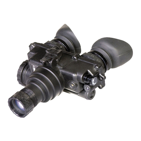
SECTION II: EquIPMENT DESCRIPTION 1-5 EquIPMENT CHARACTERISTICS, CAPABILITIES AND FEATuRES The PVS-7 includes the items shown in Figure 1-1. See Table 1-1 for Standard Components and Figure 1-1 for Optional Equipment. A. Goggle Assembly. The goggle assembly (see Figure 1-2) con- sists of four primary sub-assemblies;... - Page 14 Figure 1-1. PVS-7 Components...
- Page 15 ATN3144264 IR Spot/Flood Lens ATN3187441 Image intensifier Tube Demist Shield Assembly ATN31442632 PVS-7 Assembly ATN-PVS7-001 AA Alkaline Batteries B-3058/U Carrying Case ATN3187392 Helmet Mount Assembly ATN3256390 Neck Cord ATN3260933 Shipping/Storage Case ATN3187393 (Not Shown) *Optional equipment or Equipment having variants...
-
Page 16: Equipment Capabilities
(or illuminator) and a low battery LED indicator. The goggle automatically shuts off when disconnected from the head mount or helmet mount or flipped up on the helmet mount. There is also a high light cutoff feature that shuts off power to the goggle when it is exposed to high levels of light for 70 (±30) seconds. - Page 17 Table 1-4. Mechanical Data ITEM LIMITS Shipping and Storage Case Size: Approx. 17 ”x12”x7 ” Weight: 6.7 lbs. Soft Carrying Case Size: Approx. 14”x8” Soggle (See NOTE) Weight 1.5 lbs NOTE The weight of the PVS-7 does not include accessories.
- Page 18 ITEM LIMITS Magnification 1.0X Field of View 40° Eyepiece Focus +2 to -6 diopters Focus Range 25 cm (9.8”) to infinity Table 1-6. Environmental Data ITEM LIMITS Operating Temperature -40°C to +50°C Storage Temperature -50°C to +70°C Illumination Required Overcast starlight to moon-...
-
Page 19: Section Iii: Operation Principles
SECTION III: OPERATION PRINCIPLES 1-8 MECHANICAL FuNCTIONS Mechanical adjustments of the PVS-7 allow for physical differences between individual operators using the system. The goggle’s func- tions include the power switch, interpupillary adjustment, release latch, eye relief adjustment, diopter adjustment, IR spot/flood focus (optional), compass illumination (optional), and objective lens fo- cus. -
Page 20: Optical And Electrical Functions
The optical functions include an objective lens, image intensifier, a collimator lens and two eyepieces. The objective lens collects light reflected from the night scene by the moon, stars or night sky and inverts the image and focuses that image on the image intensifier. -
Page 21: Consumable Items
To turn the goggle back on, turn the switch to RESET/OFF position and then to ON again. 1-10 CONSuMABLE ITEMS Items listed in the Table 1-7 are recommended for operator main- tenance. Table 1-7. Consumable Items ITEM LIMITS Lens Paper... - Page 22 1-14...
-
Page 23: Chapter 2: Operating Instructions
CHAPTER 2 OPERATING INSTRuCTIONS... -
Page 24: Section I: Operating Procedures
AND MUST BE HANDLED CAREFULLY AT ALL TIMES. 2-2 CONTROLS AND INDICATORS The PVS-7 is designed to adjust for different users and corrects for most differences in eyesight. The controls and indicators for the PVS-7 are shown or described in Figure 2-1 and Tables 2-1 and 2-2. - Page 25 NOTE Some PVS-7’s contain an additional momentary IR function. For momentary IR, continue to turn the switch knob clockwise, past ON and without pulling. The switch will return to the ON position when released. RESET/ OFF- ON - Defines the switch positions.
- Page 26 Low Battery Indica- When illuminated (right eyepiece) tor (Not Shown) it indicates a low battery condition with less than 30 minutes of bat- tery life remaining. Diopter Adjustment Focuses eyepiece lens for each Ring eye without the need for glasses.
-
Page 27: Section Ii: Preventive Maintenance Checks And Services (Pmcs)
NANCE CHECKS AND SERVICES (PMCS) 2-3 PuRPOSE OF PMCS PMCS is performed daily when the PVS-7 is in use to ensure that the sight is ready at all times. Procedures are a systematic inspec- tion of the goggle that will enable you to discover defects that might cause the PVS-7 to fail on a mission. - Page 28 (range is approximately 1/3 turn). NECK CORD & LENS CAP- Check for cracked, torn or missing lens cap. Inspect cord for cuts, damage or frayed ends. Re-tie ends if neces- sary.
- Page 29 SEQUENCE ITEM TO BE INSPECTED/ PROCEDURE RESET/OFF-ON-IR/PULL SWITCH - Remove any batteries and turn the switch from RESET/ OFF to ON or IR/PULL. Each position should have a definite stopping point. Inspect for bro- ken or missing knob. HEAD MOuNT STRAPS AND PADS - Check for cuts tears, fraying, holes, cracks or defective fasteners.
- Page 30 NOTE Damaged optional items (compass, IR spo/flood, sacrificial window, demist shields) do not cause the entire end item to be “not fully mission capable”. However, the damaged item should be replaced as soon as practical to restore full capabil- ity of the system.
- Page 31 Install compass assembly and turn on goggle. When the illumination button is depressed, the compass should be visible. 3X/5X AFOCAL MAGNIFIER LENS - Check lens for scratches or damage. Check mating to objective lens by screwing in or pressing on with adapter installed.
-
Page 32: Section Iii: Assembly And Preparation
4. Inspect the goggle for obvious evidence of damage to optical surfaces, body, eyecups. RESET/OFF-ON-IR/PULL switch, bat- tery cap, etc. Ensure that all optical surfaces are clean and ready for use. Clean with lens paper. B. Installation of Batteries. - Page 33 WITH EXTREME CARE BECAUSE OF HEAT. IF YOU INHALE SULFUR DIOXIDE, SEEK MEDICAL ATTENTION. The PVS-7 will operate with either of the two battery types identified in Table 2-3. Batteries are not supplied with the PVS-7 and must be obtained. Table 2-3. Estimated Battery Life...
- Page 34 2. Check to ensure the o-ring is present. If not, replace it. 3. Observe polarity, as indicated on the outside of the battery com- partment, and insert either two AA, 1.5 Volt batteries or one 3.0 Volt BA-5567/U lithium battery into the battery compartment, plus (+) end first.
- Page 35 Figure 2-3. Installation of Demist Shields, Sacrificial window D. Installation of the Demist Shields. Perform the following pro- cedure to install the demist shields on the diopter lenses. Refer to Figure 2-3. CAUTION IF THE DEMISTING SHIELDS NEED TO BE CLEANED, MAKE SURE THE SHIELDS ARE DRY AND USE DRY LENS PAPER.
- Page 36 TO PROTECT THE OBJECTIVE LENS FROM SCRATCHES OR OTHER DAMAGE. 1. If the compass assembly or lens cap is in place, remove it. 2. Carefully push the sacrificial window over the objective lens un- til it stops. Turn the sacrificial window clockwise until it snaps into place.
- Page 37 PVS-7, remove it. 3. Carefully open the container/wrench and remove the LIF. 4. Hold the LIF by the notched end and thread it clockwise into the end of the objective lens (see Figure 2-5). 5. Using the ridged side of the container/wrench as a wrench, en- gage the ridges on the container with the ridges on the LIF and tighten the LIF hand tight.
- Page 38 7. Replace the lens cap or the sacrificial window onto the end of the objective lens and over the LIF. CAUTION BE CAREFUL NOT TO TOUCH THE GLASS SURFACES. IF YOU GET FINGERPRINTS OR CONTAMINATION ON THE GLASS SURFACES, USE LENS PAPER TO CLEAN THE LIF. IF MOIS- TURE IS NEEDED, USE YOUR BREATH TO MIST THE SURFACE OF THE GLASS.
- Page 39 Refer to Chapter 3, paragraph 3-4 for removal and replacement of the brow pads. 3. With both hands, grasp the neck pad assembly and pull the har- ness over your head and the neck pad down to the back of your neck. 2-17...
- Page 40 4. Holding the chin cup in position on chin, adjust both rear chin cup assembly straps until you feel light pressure against your chin. (DO NOT TIGHTEN). 5. Maintain the position of the chin cup and remove any slack from the front and rear chin straps.
- Page 41 2. With the catch in forward most position, place the strap over the top of the helmet, center and hook the rear bracket onto the rear of the helmet. Center the front bracket, hook in on the front of the helmet and hold it in place. (See Figure 2-8.) 3.
-
Page 42: Installation Of The Quick Disconnect Helmet Mount Assembly
Figure 2-9. Nape Strap Installation 7. Disengage the nape strap latch on the left side of the nape strap. 8. Don the helmet. 9. Engage the nape strap at the nape strap latch. Tension the chin- strap and nape strap for a secure and stable fit. - Page 43 4. With the catch in the most extended position, place the strap over the top of the helmet, center and hook the rear bracket onto the rear of the helmet. Center the front bracket hook on the front of the helmet and hold it in place.
-
Page 44: Operating Procedures
(see Figure 2-7). 2-8 OPERATING PROCEDuRES This section contains operating procedures for using the PVS-7 as a hand-held, head mounted or helmet mounted goggle. Prior to op- erating the goggle, ensure that all the steps in paragraph 2-6 have been read and performed. - Page 45 10. Adjust the eye relief distance by pressing the socket release button (See Figure 2-4) and sliding the PVS-7 fore or aft to obtain a full field of view of the image. Readjust the diopter rings for best image. NOTE Any readjustment of eye relief requires readjustment of the diopter rings.
- Page 46 Readjust the helmet straps as required for vertical adjustment. 4. Turn power switch to ON. Adjust the tilt by using the tilt adjust- ment lock knob (Figure 2-4) until you obtain a comfortable viewing angle.
- Page 47 K. Adjust the eye relief distance by pressing the socket release but- ton (see Figures 2-4, 2-5) and sliding the PVS-7 fore or aft to obtain a full field of view of the image. Readjust the diopter rings for the best image.
- Page 48 These adjustments operate independently and must be made separately. 4. Hold the PVS-7 with your left hand and fold the left eyecup over the eyepiece with your left thumb or forefinger to obstruct view through the left eyepiece.
- Page 49 2° of correct absolute magnetic bearing. Compass readings with a mounted PVS-7 (head mount or helmet mount) can be up to ±15° of correct absolute, magnetic bearing. This occurs most in the East (90°) to West (270°) and less in the 2-27...
- Page 50 The Neck cord can be used to tether the magnifier to your person to prevent losing the lens if it is dropped. To use the Neck cord, tie the end without the clip tightly around the magnifier and attach the clip to a buttonhole, belt loop or other convenient point.
-
Page 51: Preparation For Stowage
2. To Operate with the IR Spot/Flood Lens: Pull the RESET/OFF- ON-IR/PULL switch knob out and rotate clock-wise to the IR posi- tion. With the PVS-7 held to the eyes, turn the IR spot/flood until you have achieved the optimum illumination of the desired distance. - Page 52 7. Place the carrying case into the shipping/storage case (Figure 2-10); close and latch it. 8. Return to storage area. Figure 2- 10. PVS-7 Shipping/storage case 2-30...
-
Page 53: Chapter 3: Maintenance Instructions
CHAPTER 3 MAINTENANCE INSTRuCTIONS... -
Page 54: Section I: Troubleshooting Procedures
Perform the tests, inspections and corrective actions in the order they appear in the table. This table cannot list all the malfunctions that may occur, all the tests and inspections needed to find the fault, or all the corrective actions to correct the fault. - Page 55 If o-ring is missing: refer the presence of an to higher level of mainte- o-ring nance C h e c k f o r d a m - If damaged, refer to high- aged battery cap or er level of maintenance threads on battery compartment 8.
- Page 56 Check for damaged If damaged, refer to assembly higher level of mainte- nance 13 . I R s p o t / Visual Refer to higher level of flood lens will maintenance not adjust 14. Compass Visual...
- Page 57 Place the lens cap light. o n t h e o b j e c t i v e lens. Tur n PVS -7 on and observe that they shut off within 70 (± 30 ) seconds...
-
Page 58: Section Ii: Maintenance Procedures 3-2 Cleaning The Pvs-7
2. Slip the neck pad strap all the way under the upper strap reten- tion tab and then pull the lower part of the neck pad strap under the lower strap retention. - Page 59 C. Lacing the Sliding Bar Buckles. While donning and adjust- ing the head mount, it is possible for a strap to slip out of a slide fastener. Perform the following procedure to replace the strap and sliding bar buckle.
-
Page 60: Appendix A: System Optional Equipment
APPENDIX A SYSTEM OPTIONAL EquIPMENT Table A-1. System Optional Equipment ITEM DESCRIPTION QUANT PART NO Helmet Mount Assy. ATN3256390 Objective Filter Assy., LIF ATN5009737 Sacrificial Window Assy. ATN3144264 Demist Shield Assy. ATN31442632 Case, Shipping/Storage ATN3187393 Battery, Lithium B-5567/U 3X A local Lens Assy. -
Page 61: For Technical Information
FOR TECHNICAL INFORMATION ATN CORP. 1341 San Mateo Avenue South San Francisco, CA 94080 (800) 910-2862 (650) 989-5100 tel. (650) 875-0129 fax www.atncorp.com info@atncorp.com INFO-1... - Page 62 FOR NOTE INFO-2...
- Page 63 INFO-3...
- Page 64 For customer service and technical support, please contact American Technologies Network Corp. North American Office: 1341 San Mateo Avenue South San Francisco, CA 94080 phone: 800-910-2862, 650-989-5100 fax: 650-875-0129 www.atncorp.com ©2008 ATN Corporation...
Need help?
Do you have a question about the PVS7-HPT and is the answer not in the manual?
Questions and answers