Table of Contents
Advertisement
Quick Links
Advertisement
Table of Contents

Related Manuals for Seafloor HyDrone AutoNav Plus


Summary of Contents for Seafloor HyDrone AutoNav Plus
- Page 1 HyDrone™ AutoNav Plus™ User and Technical Manual Seafloor Systems, Inc...
-
Page 2: Table Of Contents
Contents Introduction ......1.1 System Overview ......... 1.2 Terms And Acronyms . - Page 3 7.4 Maintenance Schedule ........79 7.4.1 Pre-launch .
- Page 4 Set COM Port ......... . 44 COM Test .
- Page 5 105 Prop Removed ......... . 75 106 Motor Housing Removal .
-
Page 6: Introduction
Introduction System Overview Welcome to the Seafloor Systems HyDrone™ AutoNav Plus™ manual. This document provides an overview of the key features and functionalities of our cutting-edge Uncrewed Survey Vessel (USV) designed for hydrographic surveying and marine mapping applications. The HyDrone™ AutoNav Plus™... - Page 7 Information Information banner is to notify useful information for operator. Caution Caution banner is provide important information that if disregarded may result in accidental misuse or damage to the system. Important Alert Important Alert is to provide important information that if disregarded may prove harmful to personnel or equipment.
-
Page 8: System Specifications
25lbs (11.3kg). Seafloor assumes no responsibility for the loss of boats, instruments, damage to property, or any injury or fatality associated with the utilization of its products or any products that may be included or utilized in conjunction with Seafloor products. -
Page 9: Technical Support
To submit a support request, please fill out our support form on our website www.seafloorsystems.com via the big green button. You may also email us at support@seafloor.com. Please include as much information as possible: • Your Name and Company •... - Page 10 – Observe the battery from a safe distance for at least 30 minutes. – If after 30 minutes the pack appears stable, follow the battery disposal instructions below. – Under no circumstances should you return a battery to operation that has “ballooned” or been damaged in any way.
-
Page 11: Battery Charging Safety
Battery Charging Safety Important Alert Failure to follow any of the instructions and safety warnings contained within this document may cause irreversible damage to the battery pack. Information Due to shipping regulations, batteries are not shipped fully charged. All battery packs should be fully charged prior to first use. -
Page 12: System Operation
System Operation What’s Included Item Quantity Description Image* HyDrone™ Pontoons AutoNav Plus™ Frame with Pole Frame Mounts Fins Seafloor Fins M5x25mm BHSC, Frame Bolts Washer, and Lock Washer AutoNav Plus™ AutoNav Plus™ Module Paired to HyDrone™ Shoreside Antenna AutoNav Plus™ Antenna... - Page 13 To power the DC Power Cable system without the pontoons SMA 2.4GHz SMA Antennas for Antennas WiFi and Receiver N-Type 2.4GHz N-Type Antenna Antenna for Bridge Antenna N-Type Female to Female to be used 90° Coupler with 2.4GHz Antenna Remote Control Remote Control Unit for HyDrone™...
-
Page 14: What's Included
DB9 Adapter port Table 3: What’s Included *Please note that images provided are for illustrative purposes only and may not precisely represent the delivered product. Seafloor Systems reserves the right to modify any product at its discretion. -
Page 15: System Overview Diagram
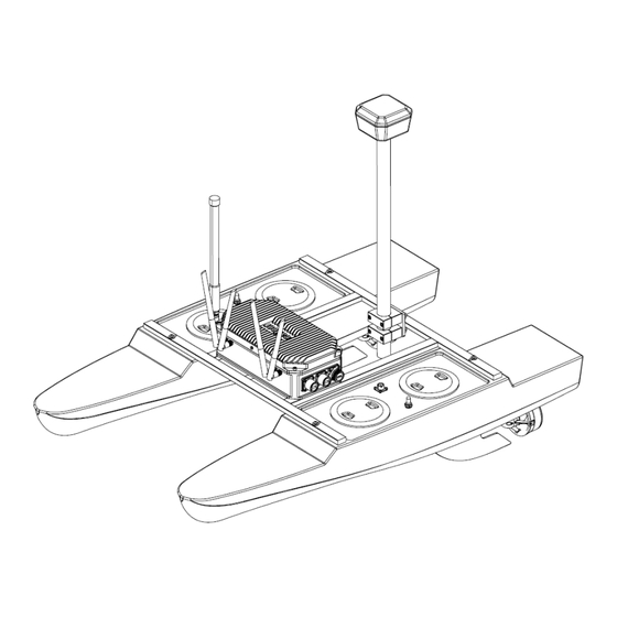
System Overview Diagram Figure 1: HyDrone™ AutoNav Plus™ System Overview... -
Page 16: Hydrone™ Autonav Plus™ Front View
Figure 2: HyDrone™ AutoNav Plus™ Front View... -
Page 17: Hydrone™ Autonav Plus™ Side View
Figure 3: HyDrone™ AutoNav Plus™ Side View... -
Page 18: Hydrone™ Autonav Plus™ Top View
Figure 4: HyDrone™ AutoNav Plus™ Top View... -
Page 19: Autonav Plus™ Layout
1. Auxiliary USB 2.0 port. 2. Auxiliary USB 2.0 port. 3. HDMI: For a monitor connection. 4. Port: To Hydrone Port Pontoon Bulkhead (Amphenol Male 6pin) 5. Starboard: To Hydrone Starboard Pontoon Bulkhead (Amphenol Female 6pin) 6. GPS: To external GPS antenna. (Amphenol Female 6pin) 7. -
Page 20: Assembling Your Hydrone™ Autonav Plus
Assembling Your HyDrone™ AutoNav Plus™ 1. Open the HyDrone™ AutoNav Plus™ case. 2. The top section that houses the frame, fins, and other components can be removed and set aside. Figure 6: Opening HyDrone™ AutoNav Plus™ Case Figure 7: Removing Top Layer 3. -
Page 21: Port(Left) Pontoon
Figure 8: Port(Left) Pontoon 4. Space the pontoons roughly 1’ (30.4cm) apart. 5. Verify the port pontoon and starboard pontoon are on their correct sides. Figure 9: Left And Right Pontoons • Power switches and Hydrone Stickers should be facing outward •... -
Page 22: Pontoons Not Spaced Correctly
Figure 10: Pontoons Not Spaced Correctly 7. Loosely install all the supplied stainless steel frame hardware. Figure 11: Frame Hardware 8. Tighten them with the supplied 3mm Allen driver. -
Page 23: Frame Attached
Figure 12: Frame Attached 9. Flip the Hydrone™upside down to gain access to the fin mount channel. 10. Slide the fin with the notch facing the bow into the fin mount channel. 11. Using the supplied 2.5mm Allen driver, tighten the set screw to hold the fin in place. Figure 13: Fin Installation 12. -
Page 24: Autonav Plus™ Mounted
Figure 14: AutoNav Plus™ Mounted 15. Screw in the 4x 2.4GHz Antennas into SMA bulkheads on the front of the AutoNav Plus™. 16. Screw in the N-Type right angle with the antenna. Figure 15: Antennas Installed 17. Unscrew the pontoon and AutoNav Plus™ bulkhead caps. Information Verify the Pontoon Power Data Cables have same gender cable ends. -
Page 25: Pontoon Power Data Cables And Hydrolite Plus Cable
Figure 16: Pontoon Power Data Cables and Hydrolite Plus Cable Figure 17: AutoNav Plus™ Installed 19. If using a software USB dongle, the USB cover can be installed now. Figure 18: USB Covers Installed... -
Page 26: Hydrone™ Autonav Plus™ Endurance Chart
Caution Excessive tightening of the shell can displace the O-ring, compromising its water resistance. USB Cover Software Dongle Installation: Figure 19: USB Cover Exploded View HyDrone™ AutoNav Plus™ Endurance Chart Figure 20: HyDrone™ AutoNav Plus™ Endurance Chart... -
Page 27: Remote Control Unit (Rcu)
Remote Control Unit (RCU) The HyDrone™ AutoNav Plus™ is controlled by a Taranis Q-X7 Access Transmitter. Information Smart Port SD Card Slot Mini USB Port Dust Cover Figure 21: Bottom View To charge the battery: • Open bottom dust cover to reveal Mini USB port. •... -
Page 28: Rcu Front View
Earphone port Trainer Port Antenna Hook Stick Stick Page Menu Exit Digital Trim Power LCD Display Figure 22: RCU Front View Remote Control Unit Functions Power Press and hold Release when the fourth loading dot appears - to power on Release when the last loading dot shows - to power off J1/J2 Throttle (Up/Down... -
Page 29: Voltage Tester
Antenna Carrying Bar Module Bay Battery Cover Figure 23: RCU Back View Information To arm HyDrone™ AutoNav Plus™: Move SA switch up and hold SH down for 5 seconds. A long alert tone (Beep——) will emit from the AutoNav Plus™, indicating system is armed. See Figure 22 To disarm HyDrone™... -
Page 30: Battery Charging
Battery Charging 3.7.1 E4 Cube Charger Important Alert Never leave batteries unattended while charging. Batteries on charge MUST remain under constant observation so that you may react quickly should any problems arise. Caution Max voltage of a 4S battery is 16.8VDC. (4.2VDC/Cell) Caution Charging LiPo Battery: with E4 Cube Balance Charger 1. -
Page 31: E4 Cube Balance Charger Technical Data
• Fourth LED indicates 100% capacity • Four LEDS will always be on when the battery is fully charged 6. When the battery is fully charged, disconnect the AC power first. Then disconnect the LiPo battery. Technical Data Property Value AC Input 100-240VAC Rated Voltage... -
Page 32: Optional - Spektrum Charger
3.7.2 Optional - Spektrum Charger Important Alert Never leave batteries unattended while charging. Batteries on charge MUST remain under constant observation so that you may react quickly should any problems arise. Caution Max voltage of a 4S battery is 16.8VDC. (4.2VDC/Cell) Caution Charging LiPo Battery: with Spektrum Charger... -
Page 33: Spektrum Charger Settings
6. Connect the female XT90 from the 4S LiPo into the male XT90 on the adapter cable. Then, connect the balance lead into the charger. 7. Press and release the menu/select button to display the charger settings list. Task Select Charge, Discharge, or Storage Battery (Type) Select LiPo Cells (Cell Count) -
Page 34: Spektrum Charger Technical Data
Information Charger error – If the charger displays an error, follow the on-screen prompts to remedy the error. If necessary, disconnect the battery from the output and balance ports, disconnect the power supply, and then restart the charger. Technical Data Input Voltage 100-240 VAC Charge Current... -
Page 35: Optional - Tattu Charger
3.7.3 Optional - Tattu Charger Important Alert Never leave batteries unattended while charging. Batteries on charge MUST remain under constant observation so that you may react quickly should any problems arise. Caution Max voltage of a 4S battery is 16.8VDC. (4.2VDC/Cell) Caution Charging LiPo Battery: with Tattu Charger... -
Page 36: Tattu Charger Operation
ii. Press and hold the CH A or CH B button to start charge operation. Figure 29: Tattu Charger Operation 6. Press and hold the corresponding channel button to pause the charging operation. 7. During the charging process the main screen will provide the following information: (a) Charge time (b) Charge percentage (c) Status... -
Page 37: Pre-Launch Check List
Technical Data Input Voltage 100-240 VAC Max Charge Current 25.0A Discharge Current 6.0A Max Charge Power 2x500W Max Discharge Power 2x70W Balance Cells 1-7s Operating Temperature 0°C - 60°C Storage Temperature -20°C - 60°C Table 11: Tattu Charger Technical Data Pre-Launch Check List •... -
Page 38: Hydrone™ Autonav Plus™ Power On Procedure
If not given enough time, the connection will attempt to initiate and fail. • It is not recommended to use an Ethernet to USB adapter. • If multiple Seafloor Systems vessels are operating in the same zone. Please contact Seafloor Systems to modify Bridge settings. -
Page 39: Shoreside Hardware Setup
Hardware setup: 1. Connect the 10ft(3m) Ethernet cable into the Shoreside Bridge Antenna. 2. Connect the other end of the Ethernet cable into the PoE adapter. 3. Connect the PoE Ethernet adapter into the shoreside laptop being used to remote into the Hy- Drone™... -
Page 40: Network Adapters
4. Open More Network Adapter Options. Figure 33: Network Adapters 5. Right click on the Ethernet port with the description ”Unidentified Network” and select Properties. Figure 34: Ethernet Properties 6. Double click ”Internet Protocol Version 4 (TCP/IPv4). Figure 35: Internet Protocol... -
Page 41: Ethernet Settings
7. Change the follow settings: Figure 36: Ethernet Settings • Use the following IP address: – IP address: 192.168.168.4 – Subnet mask: 255.255.255.0 • Leave Preferred DNS and Alternate DNS servers blank. To Login: 1. Search ”Remote Desktop” in the windows task bar and select it. Figure 37: Taskbar Search 2. -
Page 42: Remote Desktop Connection
Figure 38: Remote Desktop Connection 4. Click Connect. 5. Password is ”Seafloor”. -
Page 43: Manual Operation
Mission Planner Information Seafloor Systems AutoNav Plus™ requires two NMEA input GPS strings. GPS/GNSS system not pro- vided by Seafloor, will need to be configured to output the required NMEA strings. • GGA and RMC at 5Hz with a GP Talker ID(Prefix) at 38400 baud rate. RS232 Protocol with DB9 connector. -
Page 44: Com Port
1. Open Mission Planner. 2. Connect to the AutoNav Plus™. Figure 39: COM Port • Choose Mavlink COM port • 115200 baud rate 3. Click PLAN. 4. Find your survey area. 5. Click the circled polygon in the top left and select ’Draw a Polygon’. Figure 40: Polygon Select... -
Page 45: Simplegrid Select
6. Click on the survey area to define the borders of the survey. Use mouse to drop red polygon points to outline survey area. • Give enough distance for tides. Can also manually drive the HyDrone™ AutoNav Plus™ to desired location and drop polygon points at each extent. 7. -
Page 46: Simplegrid Settings
Figure 42: SimpleGrid Settings 8. Delete the first command, speed change. Figure 43: Delete DO CHANGE SPEED • By deleting it will revert back to default survey speed. 9. Click ’Write’ on the right panel. Figure 44: Write Mission... -
Page 47: Hypack
Hypack Information Seafloor Systems AutoNav Plus™ requires two NMEA input GPS strings. GPS/GNSS system not pro- vided by Seafloor, will need to be configured to output the required NMEA strings. • GGA and RMC at 5Hz with a GP Talker ID(Prefix) at 38400 baud rate. RS232 Protocol with DB9 connector. -
Page 48: Add Mobile
Figure 45: Add Mobile 4. Under the new Mobile, add Mavlink driver. Figure 46: Add Mavlink Driver... -
Page 49: Set Com Port
5. Device Connection is Serial. Figure 47: Set COM Port 6. Set COM number. Can be verified in Device Manager. 7. Set Baud Rate to 115200. 8. Use the Comport Test to verify data is coming through the selected COM port. Figure 48: COM Test... -
Page 50: Line Editor
Line Planning: 1. Create the line plan using Hypack’s standard Line Plane Editor. Figure 49: Line Editor 2. Right click every other line and select Reverse Order. Figure 50: Reverse Every Other Line 3. Start Hypack Survey/Hysweep. 4. Mavlink Driver will say Armed or Unarmed. USV must be Armed to Start Mission. -
Page 51: Hydrone™ Autonav Plus™ Power Off Procedure
Figure 51: Mavlink Driver Control • If the status flashes between Armed/Disarmed, it’s a bug. System is Armed. 5. Using the Mavlink Driver, you can toggle Auto mode by selecting Start Mission. Mavlink driver button functionality: • Start Mission – The HyDrone™ AutoNav Plus™ will navigate the current line file. –... -
Page 52: Fail-Safe
RCU range. • It is possible to program other fail safe parameters. By default these are all disabled as there is a potential to interrupt the survey plan. Please contact Seafloor Systems if you wish to enable. 3.15 Voltage Monitoring 3.15.1... -
Page 53: Autonav Plus™ Voltage Monitor
To view HyDrone™ AutoNav Plus™ battery voltage: 1. Power on the RCU. (Refer to 3.5) 2. Power on the AutoNav Plus™. 3. Hold down PAGE button to access the DISPLAY screen. Figure 53: Display Page • Left voltage(A2) is the starboard pontoon battery. •... -
Page 54: Autonav Plus™ Voltage Monitor
Figure 55: AutoNav Plus™ Voltage Monitor Voltage Monitor Functions: 1. Connect: To connect to the Voltage Monitor application. 2. Calibrate: To calibrate the Voltage Monitor values to match real world values. 3. Close: To close the application. 4. Port Battery: Voltage value of the port pontoon. 5. -
Page 55: Frequently Asked Questions (Faq)
Frequently Asked Questions (FAQ) • Why does the prop not spin in reverse? – The ESC is not programmed to “Forward and Reverse” running mode. Refer to 6.6 for ESC Programming. • Why does the thruster motor not respond while the HyDrone™ AutoNav Plus™ is powered? Alert tone of beep-, beep- (1 second interval) is heard. -
Page 56: Troubleshooting
Troubleshooting Propeller Orientation And Rotation If the propellers on a HyDrone™ AutoNav Plus™ are rotating in the wrong direction, it will cause the boat to move in circles when attempting to go forward. Similarly, installing the wrong propeller will also lead to same issue. -
Page 57: Autonav Errors
Figure 59: W30 CW Prop AutoNav Errors Common Errors: If the Autonomous Operation is not behaving as expected, open and connect to Mission Planner. The HUD will show errors. • EKF3 waiting for GPS config data – No GPS input. Check GNSS output. Use a Null Modem if needed. •... -
Page 58: Configure Procedure
Configure Procedure RCU Receiver Binding Procedure Archer Plus R6 Binding: Registration is only required if the RCU or Receiver (RCVR) was replaced. Skip to step 7 to bind for either receivers. 1. Refer to 3.5 for button or switch location on RCU. 2. -
Page 59: Rcu Telemetry Configuration Procedure
Figure 63: Archer Plus R6 • It is suggested to disconnect the main cable to remove power and reconnect when power is needed. iii. On the RCU, ’Waiting...’ will be replaced with the model name. iv. Press Enter to confirm, registration complete. v. -
Page 60: Model Select Screen
3. Quick press ’Menu’ on the RCU. Figure 66: Model Select Screen 4. Quick press ’Page’ to switch to TELEMETRY Page 12/13. Figure 67: Telemetry Page 5. Scroll down and select ”Delete all sensors”. Figure 68: Delete All Sensors Figure 69: Delete All Sensors Pop-Up 6. -
Page 61: Rcu Calibration Procedure
Figure 70: Discover New Sensors 7. A2 sensor will be active. 8. Select the A2 sensor. Figure 71: A2 Sensor Page 9. At the top of the screen is the pontoon voltage. 10. Scroll down to the Ratio. Modify the value to set the pontoon voltage. Use the supplied Voltage Checker to check the pontoon voltage. -
Page 62: Main Screen
1. HyDrone™ AutoNav Plus™ must be powered off. 2. Power on the RCU. (Refer to 3.5) Figure 73: Main Screen 3. Hold down ’Menu’ button. Figure 74: RCU Settings 4. Quick press ’Page’ to switch to HARDWARE to Page 6/7. Figure 75: Hardware Page 5. -
Page 63: Rcu Autonav Calibration
RCU AutoNav Calibration 1. Power on the RCU. 2. Power on the AutoNav Plus™. 3. Connect to the AutoNav Plus™. (USB Cable is 115200 baud rate) 4. Vessel MUST be disarmed. 5. Select Setup tab. Figure 77: Setup Tab 6. Select Mandatory Hardware. 7. -
Page 64: Radio Calibration Steps
Figure 78: Radio Calibration Steps 8. Select Calibrate Radio. (a) Power Warning (b) Radio Cal Instructions Figure 79: Pop Ups 9. Move all joystick to their min and max positions. 10. Move all switches to each position. Be sure to arm and disarm. 11. -
Page 65: Esc Calibration Procedure
Figure 80: Radio Calibration Verification 12. Select Click when Done. Figure 81: Click When Done 13. A page will popup indicating the new min and max values. Press OK. (Refer to Figure 80) ESC Calibration Procedure 1. Calibrate one ESC at a time. 2. -
Page 66: Esc Programming Procedure
5. Two short Beep- Beep- tones will be heard, confirming the full throttle position. 6. Immediately release the Throttle Control to the neutral position. 7. A steady and long beep— can be heard, confirming the neutral position. “Beep- Beep-” “Beep--” Figure 82: Joystick Position 8. -
Page 67: Autonav Plus™ Accel Calibration Procedure
Figure 83: ESC Programming Card Ports 2. Connect the ribbon cable to the ESC. Pay attention to the connector orientation. Figure 84: ESC Programming Card Connection 3. Power on the HyDrone™ AutoNav Plus™. The Programming Card will power on. 4. Using the chart below, match the Items with the Values. 5. -
Page 68: Accel Calibration
2. Install DC Power Cable and a 4S LiPo battery. 3. Open Mission Planner. 4. Connect to the AutoNav Plus™ with 115200 baud rate. 5. AutoNav Plus™ must be disarmed. 6. Select Setup tab. Figure 85: Accel Calibration 7. Select Mandatory Hardware. 8. -
Page 69: Accel Calibration Steps
Figure 86: Accel Calibration Steps 9. Set the AutoNav Plus™ on a level surface. 10. Select Calibrate Accel(3 axis). You will rotate and hold the AutoNav Plus™ on each axis. Instruc- tions will be present during the process. Bulkheads are always facing backwards(stern). Figure 87: Accel Calibration In Process (a) First is a level surface. -
Page 70: Autonav Plus™ Compass Calibration Procedure
Figure 88: Accel Calibration Complete 12. Set the AutoNav Plus™ on a level surface again. 13. Select Calibration Level. (See Figure 85) AutoNav Plus™ Compass Calibration Procedure Information Compass calibration should be performed away from metal buildings and any electronic equipment. 1. -
Page 71: Compass Calibration Steps
Figure 89: Compass Calibration Steps 11. Rotate the AutoNav Plus™ 360 degrees on the X, Y, and Z axis. Figure 90: Compass Calibration Progress 12. Mag 1 green progress bar will start increasing. -
Page 72: Compass Calibration Complete
13. A ”Please reboot the autopilot” popup will indicate compass calibration is complete. Figure 91: Compass Calibration Complete 14. Select ’OK’. 15. Press CTRL and F keys to reboot the autopilot hardware separately from the entire AutoNav Plus™ system. 16. Select ’reboot pixhawk’. -
Page 73: Ctrl-F Screen
Figure 92: CTRL-F Screen 17. The autopilot hardware will reboot. Mission Planner will disconnect and automatically reconnect. (If it does not, you can manually connect) Figure 93: Reboot Complete 18. Calibration complete. -
Page 74: Service And Maintenance
Service And Maintenance Maintaining Your Investment Maintaining your HyDrone™ AutoNav Plus™ asset is essential for its reliable performance. Regular maintenance includes routine checks of propulsion system, sensor, and electronics to ensure they are in optimal working condition. Keeping the hull clean as well as verifying the integrity of communication links and power sources, is crucial. -
Page 75: Propeller Replacement
Figure 95: Thruster Adapter Plate 6. Install new thruster motor wires through cable gland. 7. Install the cable gland seal and nut. • Ensure the seal sits in it’s notched location for proper sealing. 8. Install new thruster onto the pontoon mating plate. 9. -
Page 76: Thruster Removal
Figure 96: Thruster Removal 2. Remove the 4x M3x6 bolts with a 2mm Allen driver. Figure 97: Thruster Adapter Plate Removal 3. Remove the 5x screws with a #3 Philips driver. -
Page 77: Thruster Housing Removal
Figure 98: Thruster Housing Removal 4. Remove the 2x screws with a #3 Philips driver. Figure 99: Prop Removal 5. Remove the prop. The prop may be suctioned to the motor housing. Use care when removing. -
Page 78: Motor Cleaning
Figure 100: Prop Removed 6. Install the replacement W30 prop. 7. Follow the instructions in reverse order for reassembly. 7.3.3 Motor Cleaning Caution Use Vibra-tite with all hardware. Plastic may become damaged if Vibra-tite instructions are not properly followed. 1. Remove the 2x M5 nyloc with a 8mm wrench. Figure 101: Thruster Removal... -
Page 79: 102 Thruster Adapter Plate Removal
2. Remove the 4x M3x6 bolts with a 2mm Allen driver. Figure 102: Thruster Adapter Plate Removal 3. Remove the 5x screws with a #3 Philips driver. Figure 103: Thruster Housing Removal 4. Remove the 2x screws with a #3 Philips driver. -
Page 80: 104 Prop Removal
Figure 104: Prop Removal 5. Remove the prop. The prop may be suctioned to the motor housing. Use care when removing. Figure 105: Prop Removed 6. Remove the 2x M3 bolts with a 2.5mm Allen Driver Figure 106: Motor Housing Removal 7. -
Page 81: Rcu Rtc Battery Replacement
Figure 107: Rotor Removal 8. The motor rotor and stator are magnets. To remove, pull on the motor rotor to slide off. Figure 108: Stator And Rotor 9. Inspect the magnets and protective coverings. Clean with mild soap and water. 10. -
Page 82: 109 Rcu 2X Screw Locations
Figure 109: RCU 2x Screw Locations 3. Remove the module bay cover. 4. Remove the battery cover. (Figure 23) 5. Disconnect the battery. -
Page 83: 110 Rcu Additional Screw Locations
Figure 110: RCU Additional Screw Locations 6. Remote the additional two Phillip screws. 7. Carefully split case of the RCU. Figure 111: RCU RTC Location 8. Locate the RTC battery(circled red in Figure 111) and remove it. 9. Replace it with a new CR1220 battery. -
Page 84: Maintenance Schedule
10. Carefully put the two case halves together. Verify the module bay pins (circled yellow in Figure 111) slide through the slot (Figure 23). 11. Screw in the four Philip screws. 12. Connect the battery. 13. Install battery spacing foam. 14. -
Page 85: Technical Diagrams
Technical Diagrams Beaufort Sea State Chart Estimating Wind Speed and Sea State with Visual Clues Beaufort Wind Wave Wind Speed Visual Clues number Description Height Calm 0 knots 0 feet Sea is like a mirror. Smoke rises vertically. Ripples with the appearance of scales are formed, but without foam crests. Light Air 1-3 kts <... -
Page 86: Block Diagrams
Block Diagrams THRUSTER THRUSTER SHORESIDE AUTONAV ANTENNA PLUS SHORESIDE SONAR TOPSIDE TRANSDUCER Figure 113: Block Diagram... -
Page 87: Electrical Diagrams
Electrical Diagrams Figure 114: HyDrone™ Electrical Diagram... -
Page 88: 115 Autonav Plus™ Bulkhead Pinout (See Figure 5 For Bulkhead Locations)
Figure 115: AutoNav Plus™ Bulkhead Pinout (See Figure 5 for Bulkhead Locations) -
Page 89: 116 Port Pontoon Power Data Cable Diagram
Figure 116: Port Pontoon Power Data Cable Diagram... -
Page 90: 117 Starboard Pontoon Power Data Cable Diagram
Figure 117: Starboard Pontoon Power Data Cable Diagram... -
Page 91: 118 Autonav Plus™ To Hydrolite Plus Echo Sounder Data Cable Diagram
Figure 118: AutoNav Plus™ To Hydrolite Plus Echo Sounder Data Cable Diagram... -
Page 92: Mechanical Diagrams
Mechanical Diagrams Figure 119: Side View Diagram... -
Page 93: 120 Front View Diagram
Figure 120: Front View Diagram... -
Page 94: 121 Top View Diagram
Figure 121: Top View Diagram... - Page 95 Revision History Revision Date Author(s) Description 3.27.2024 Created 6.17.2024 Revised Support section: Company URL and phone in- structions 7.29.2024 Revised Operating Hours, Added Tattu Charger...
Need help?
Do you have a question about the HyDrone AutoNav Plus and is the answer not in the manual?
Questions and answers