Sign In
Upload
Manuals
Brands
Seafloor Manuals
Marine Equipment
HyDrone AutoNav Plus
Seafloor HyDrone AutoNav Plus Manuals
Manuals and User Guides for Seafloor HyDrone AutoNav Plus. We have
1
Seafloor HyDrone AutoNav Plus manual available for free PDF download: User And Technical Manual
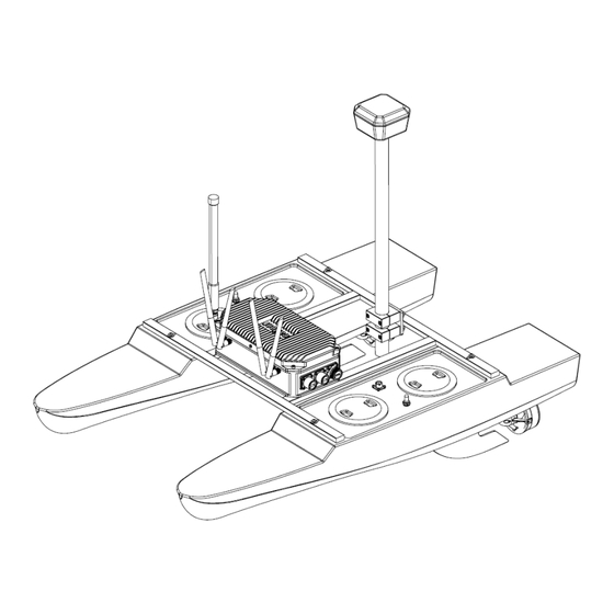
Seafloor HyDrone AutoNav Plus User And Technical Manual (95 pages)
Brand:
Seafloor
| Category:
Marine Equipment
| Size: 74 MB
Table of Contents
Table of Contents
2
Introduction
6
System Overview
6
Terms and Acronyms
6
System Specifications
8
System Limitations
8
Warranty
8
Technical Support
9
Safety
9
Battery Safety
9
Battery Charging Safety
11
Vessel Safety
11
System Operation
12
What's Included
12
What's Included
14
System Overview Diagram
15
Hydrone™ Autonav Plus™ System Overview
15
Hydrone™ Autonav Plus™ Front View
16
Hydrone™ Autonav Plus™ Side View
17
Hydrone™ Autonav Plus™ Top View
18
Autonav Plus™ Layout
19
Assembling Your Hydrone™ Autonav Plus
20
Opening Hydrone™ Autonav Plus™ Case
20
Removing Top Layer
20
Port(Left) Pontoon
21
Left and Right Pontoons
21
Pontoons Not Spaced Correctly
22
Frame Hardware
22
Frame Attached
23
Fin Installation
23
Autonav Plus™ Mounted
24
Antennas Installed
24
Pontoon Power Data Cables and Hydrolite Plus Cable
25
Autonav Plus™ Installed
25
USB Covers Installed
25
Hydrone™ Autonav Plus™ Endurance Chart
26
USB Cover Exploded View
26
Remote Control Unit (RCU)
27
Bottom View
27
RCU Front View
28
RCU Functions
28
Voltage Tester
29
RCU Back View
29
Lipo Voltage Tester
29
Battery Charging
30
E4 Cube Charger
30
Cube Balance Charger Power
30
Cube Balance Charger Connection
30
E4 Cube Balance Charger Technical Data
31
Optional - Spektrum Charger
32
Spektrum Charger Layout
32
Spektrum Charger Settings
33
Spektrum Charger Technical Data
34
Optional - Tattu Charger
35
Tattu Charger Layout
35
Tattu Charger Operation
36
Pre-Launch Check List
37
Tattu Charger Technical Data
37
Hydrone™ Autonav Plus™ Power on Procedure
38
Shoreside Setup Communications
38
Shoreside Hardware Setup
39
Network and Internet Settings
39
Advanced Network Settings
39
Network Adapters
40
Ethernet Properties
40
Internet Protocol
40
Ethernet Settings
41
Taskbar Search
41
Remote Desktop Connection
42
Manual Operation
43
Autonomous Operation
43
Mission Planner
43
COM Port
44
Polygon Select
44
Simplegrid Select
45
Simplegrid Settings
45
Simplegrid Settings
46
Delete DO CHANGE SPEED
46
Write Mission
46
Hypack
47
Add Mobile
48
Add Mavlink Driver
48
Set COM Port
49
COM Test
49
Line Editor
50
Reverse Every Other Line
50
Hydrone™ Autonav Plus™ Power off Procedure
51
Mavlink Driver Control
51
Fail-Safe
52
Voltage Monitoring
52
RCU Voltage Monitor
52
Main Screen
52
Autonav Plus™ Voltage Monitor
53
Display Page
53
Battery Monitor Application Icon
53
Autonav Plus™ Voltage Monitor
54
Caption
54
Frequently Asked Questions (FAQ)
55
Troubleshooting
56
Propeller Orientation and Rotation
56
Hydrone™ Autonav Plus™ Prop Rotation (Colors Illustrate Maritime Navigation Lights)
56
W30 CCW Prop
56
Autonav Errors
57
W30 CW Prop
57
Configure Procedure
58
RCU Receiver Binding Procedure
58
Model Select Screen
58
Internal RF
58
Waiting to Register
58
RCU Telemetry Configuration Procedure
59
Archer Plus R6
59
Binding Screen - Simurx1/2 Is Only Used for Simulation
59
Bind Successful
59
Model Select Screen
60
Telemetry Page
60
Delete All Sensors
60
Delete All Sensors Pop-Up
60
RCU Calibration Procedure
61
Discover New Sensors
61
A2 Sensor Page
61
Display Page
61
Main Screen
62
RCU Settings
62
Hardware Page
62
Start of Calibration
62
RCU Autonav Calibration
63
Setup Tab
63
Radio Calibration Steps
64
Pop Ups
64
ESC Calibration Procedure
65
Radio Calibration Verification
65
Click When Done
65
ESC Programming Procedure
66
Joystick Position
66
Autonav Plus™ Accel Calibration Procedure
67
ESC Programming Card Ports
67
ESC Programming Card Connection
67
ESC Programming Values
67
Accel Calibration
68
Accel Calibration Steps
69
Accel Calibration in Process
69
Autonav Plus™ Compass Calibration Procedure
70
Accel Calibration Complete
70
Compass Calibration Steps
71
Compass Calibration Progress
71
Compass Calibration Complete
72
CTRL-F Screen
73
Reboot Complete
73
Service and Maintenance
74
Maintaining Your Investment
74
Storage
74
Service
74
Thruster Replacement
74
Thruster Removal
74
Propeller Replacement
75
Thruster Adapter Plate
75
Thruster Removal
76
Thruster Adapter Plate Removal
76
Thruster Housing Removal
77
Prop Removal
77
Motor Cleaning
78
100 Prop Removed
78
101 Thruster Removal
78
102 Thruster Adapter Plate Removal
79
103 Thruster Housing Removal
79
104 Prop Removal
80
105 Prop Removed
80
106 Motor Housing Removal
80
RCU RTC Battery Replacement
81
107 Rotor Removal
81
108 Stator and Rotor
81
109 RCU 2X Screw Locations
82
110 RCU Additional Screw Locations
83
111 RCU RTC Location
83
Maintenance Schedule
84
Pre-Launch
84
After Recovery
84
Monthly
84
Technical Diagrams
85
Beaufort Sea State Chart
85
112 Beaufort Sea State
85
Block Diagrams
86
113 Block Diagram
86
Electrical Diagrams
87
114 Hydrone™ Electrical Diagram
87
115 Autonav Plus™ Bulkhead Pinout (See Figure 5 for Bulkhead Locations)
88
116 Port Pontoon Power Data Cable Diagram
89
117 Starboard Pontoon Power Data Cable Diagram
90
118 Autonav Plus™ to Hydrolite Plus Echo Sounder Data Cable Diagram
91
Mechanical Diagrams
92
119 Side View Diagram
92
120 Front View Diagram
93
121 Top View Diagram
94
Advertisement
Advertisement
Related Products
Seafloor Hydrone RCV Servo
Seafloor HydroLite-TM
Seafloor HyDrone-G2 RCV
Seafloor HyDrone-G2 ACV
Seafloor HyDrone ASV
Seafloor HyDrone RCV
Seafloor HydroLite-TM PLUS
Seafloor AutoNav
Seafloor EchoBoat 160 ASV
Seafloor EchoBoat 160 RCV
Seafloor Categories
Marine Equipment
Measuring Instruments
Controller
Boating Equipment
More Seafloor Manuals
Login
Sign In
OR
Sign in with Facebook
Sign in with Google
Upload manual
Upload from disk
Upload from URL