Table of Contents
Advertisement
Quick Links
Advertisement
Table of Contents

Related Manuals for Seafloor HydroCat 180


Summary of Contents for Seafloor HydroCat 180
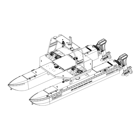
- Page 1 HydroCat™ 180 User and Technical Manual Seafloor Systems, Inc...
-
Page 2: Table Of Contents
Contents Introduction ......System Overview ........1.2 Terms And Acronyms . - Page 3 7.2 Storage ..........76 7.3 Service .
- Page 4 Write Mission ......... . . 39 Add Mobile .
- Page 5 HydroCat™ 180 Offset Diagram ....... . . 84 100 Block Diagram ......... . 85 101 Gimbal Layer 1 Block Electrical Diagram .
- Page 6 List of Tables What’s Included ......... 12 RCU Functions .
-
Page 7: Introduction
Introduction System Overview Welcome to the Seafloor Systems HydroCat™ 180 manual. This document provides an overview of the key features and functionalities of our cutting-edge Uncrewed Survey Vessel (USV) designed for hydrographic surveying and marine mapping applications. The HydroCat™ 180 offers advanced hydrographic surveying capabilities, autonomous operation, flexible payload options, and real-time data viewing. - Page 8 Information Information banner is to notify useful information for operator. Caution Caution banner is provide important information that if disregarded may result in accidental misuse or damage to the system. Important Alert Important Alert is to provide important information that if disregarded may prove harmful to personnel or equipment.
-
Page 9: System Specifications
System Specifications Survey Speed 2.5-4 knots (1.3-2m/s)* Top Speed 9.7 knots (5m/s) Sonar Pole Up Length 18ft (5.5m) Width 8.5ft (2.5m) Draft 2.4ft (0.74m) Air Draft 7.5ft (2.3m) Hull Material Corrosion Resistant Aluminum Hardware 316 Stainless Steel Weight (Base Boat) 1700lbs (725kg) Payload 800lbs (365kg) -
Page 10: Water Towing
800lbs (362.9kg). Seafloor assumes no responsibility for the loss of boats, instruments, damage to property, or any injury or fatality associated with the utilization of its products or any products that may be included or utilized in conjunction with Seafloor products. -
Page 11: Technical Support
To submit a support request, please fill out our support form on our website www.seafloor.com via the big green button. You may also email us at support@seafloor.com. Please include as much information as possible: •... -
Page 12: Safety
Safety Battery Safety Please read through these instructions carefully before you operate the HydroCat™ 180. Important Alert Danger to life from electric shock. Contact with uninsulated or damaged parts can result in severe physical injuries. • Avoid touching contacts. • Do not undertake any repair work whatsoever on Power 48-5000 pontoon batteries. •... -
Page 13: Vessel Safety
• Do not charge any type of battery on or near any flammable materials including in or near your vessel. • Never leave batteries unattended while charging. While batteries are charging they MUST remain under constant observation so that you may react quickly should any problems arise. •... -
Page 14: System Operation
System Operation HydroCat™ 180 Assembly Figure 2: Assembly Overview... -
Page 15: Gimbal Installation
Tools Required(Not Supplied): • QTY 2 - Lifting straps, 2k lbs (907 Kg) limit each, 20ft (6m) length • QTY 4 - D-Ring shackles • Ratcheting socket wrench • 22mm Deep socket • 3/4” Socket • 3/4” Open ended wrench Hardware Required(Supplied): •... -
Page 16: Top Clamp Installation
6. Once the gimbal is in position, install the bearing top clamp. Figure 4: Top Clamp Installation 7. Install the M14 hardware to secure the bearing top clamp. Do not tighten yet. 8. Install shock hardware: • Installation order: Bolt, Sleeve Bearing, Shock, Sleeve Bearing, Washer, Nyloc. Figure 5: Shock Installation 9. -
Page 17: What's Included
10. Slip the cold shrink over both pontoon data cables.(Cable KK). 11. Connect the two gimbal to pontoon data cables(Cable KK). (Figure 104 12. Pull cold shrink tab while holding the cold shrink over the connector. What’s Included Item Quantity Description Image* HydroCat™... -
Page 18: What's Included
DB9 Adapter port Table 3: What’s Included *Please note that images provided are for illustrative purposes only and may not precisely represent the delivered product. Seafloor Systems reserves the right to modify any product at its discretion. -
Page 19: System Overview Diagram
System Overview Diagram Figure 6: HydroCat™ 180 System Overview... -
Page 20: Hydrocat™ 180 Front View
Figure 7: HydroCat™ 180 Front View... -
Page 21: Hydrocat™ 180 Pontoon
Figure 8: HydroCat™ 180 Pontoon... -
Page 22: Hydrocat™ 180 Gimbal Deck
Figure 9: HydroCat™ 180 Gimbal Deck... -
Page 23: Hydrocat™ 180 Payload
Figure 10: HydroCat™ 180 Payload... -
Page 24: Hydrocat™ 180 Control Layout
HydroCat™ 180 Control Layout Gimbal: 1. SmartCast Manual Override Switch • Switch towards stern - lowers SVP • Switch towards bow - raises SVP 2. Sonar Pole Manual Override Switch • Switch towards stern - lowers Sonar Pole • Switch towards bow - raises Sonar Pole 3. -
Page 25: Port Thruster Bulkhead Panel
Thruster Bulkhead Panel Port: 1. Thruster Trim Switch • Switch up - Thruster Up • Switch down - Thruster down 2. Thruster Trim Communication Cable 3. Thruster Communication Cable 4. Positive Thruster Battery Cable 5. Negative Thruster Battery Cable 6. Hydraulic Steering Communication Cable 7. -
Page 26: Starboard Thruster Bulkhead Panel
Starboard: 1. Thruster Trim Switch • Switch up - Thruster Up • Switch down - Thruster down 2. Thruster Trim Communication Cable 3. Thruster Communication Cable 4. Positive Thruster Battery Cable 5. Negative Thruster Battery Cable 6. Hydraulic Steering Communication Cable 7. -
Page 27: Gimbal Rear Bulkhead Panel
Gimbal Bulkhead Panels Rear: 1. Port Pontoon Cable 2. Port Sonar Pole Actuator 3. Starboard Sonar Pole Actuator 4. Starboard Pontoon Cable Rear View Figure 14: Gimbal Rear Bulkhead Panel... -
Page 28: Gimbal Front Bulkhead Panel
Front: 1. Unused 2. Unused 3. Unused 4. SmartCast Front View Figure 15: Gimbal Front Bulkhead Panel... -
Page 29: Hydrocat™ 180 Endurance Chart
HydroCat™ 180 Endurance Chart Figure 16: HydroCat™ 180 Endurance Chart Payload batteries have an estimated 10 hours of endurance. (Conditions dependant, refer to 1.4) Remote Control Unit (RCU) The HydroCat™ 180 is controlled by a Taranis Q-X7 Access Transmitter. Information Figure 17: Bottom View To charge the battery: •... -
Page 30: Rcu Front View
Figure 18: RCU Front View Remote Control Unit Functions Power Press and hold (Not labeled - Release when the fourth loading dot appears - to power on Right below Hook) Release when the last loading dot shows - to power off J1/J2 Throttle (Up/Down Skid Steering (Left/Right) -
Page 31: Battery Charging
Figure 19: Back View Important Alert For safety you must arm the HydroCat™ 180 to allow the thrusters to function. Always disarm or power off the vessel when working near the props. To arm the HydroCat™ 180: Move SA switch up and hold SH down for 5 seconds. See Figure 18 To disarm the HydroCat™... -
Page 32: Charging Connector - Power
2. Connect Fast Charger output connector into the pontoon charging connector. Figure 20: Charging Connector - Power 3. Remove waterproof signal cable cap. Do NOT lose it. 4. Connect Fast Charger data cable into pontoon signal cable. Figure 21: Charging Connector - Data 5. -
Page 33: Gimbal Charging
3. Attach pontoon signal cable cap. 4. Disconnect Fast Charger output connector from the pontoon charging connector. 5. Repeat for the opposite side. Caution Charger will show three dots if the batteries are above 49V. They cannot be topped off. Technical Data Property Value... -
Page 34: Long Range Module Battery Charging
Figure 22: NOCO Battery Charger 5. Charging complete when each channel has a solid green Light Emitting Diode(LED) 6. Disconnect AC power source when all channels are fully charged Technical Data Property Value AC Input 100-240VAC Rated Voltage Final Charging Voltage 14.8V Maximum Voltage At The Terminals 14.8V... -
Page 35: Cube Balance Charger Power
Figure 23: Cube Balance Charger Power 3. Charger will run a self-check. Wait for LED 1, 3 and LED 2, 4 to blink alternately before proceeding. 4. Connect the 2S 7.2V LiPo battery balance cable to the 2S (left) port. Figure 24: Cube Balance Charger Connection 5. -
Page 36: Hydrocat™ 180 Power On Procedure
HydroCat™ 180 Power On Procedure Information Important Note: • Shut down pontoon batteries at 39VDC. (Refer to 1.4) • Recommended to shutdown gimbal batteries at 11.6VDC. (Refer to 1.4) • Voltage can be viewed on the Voltage Sensor, see Figure 49 and 3.4 for internal Voltage Displays) 1. -
Page 37: Sonar Pole Actuators
If not given enough time, the connection will attempt to initiate and fail. • It is not recommended to use an Ethernet to USB adapter. • If multiple Seafloor Systems vessels are operating in the same zone. Please contact Seafloor Systems to modify Bridge settings. -
Page 38: Shoreside Hardware Setup
Figure 27: Shoreside Hardware Setup Software setup(Windows 11): 1. Right click the WiFi icon on the taskbar. Figure 28: Network And Internet Settings 2. Open Network and Internet Settings. 3. Open Advanced Network Settings. Figure 29: Advanced Network Settings 4. Open More Network Adapter Options. Figure 30: Network Adapters 5. -
Page 39: Ethernet Properties
Figure 31: Ethernet Properties 6. Double click ”Internet Protocol Version 4 (TCP/IPv4) Figure 32: Internet Protocol... -
Page 40: Ethernet Settings
7. Change the follow settings: Figure 33: Ethernet Settings • Use the following IP address: – IP address: 192.168.168.4 – Subnet mask: 255.255.255.0 • Leave Preferred DNS and Alternate DNS servers blank. To Login: 1. Search ”Remote Desktop” in the windows task bar and select it. Figure 34: Taskbar Search 2. -
Page 41: Remote Desktop Connection
Figure 35: Remote Desktop Connection 4. Click Connect 5. Password is ”Seafloor”... -
Page 42: Manual Operation
Mission Planner Information Seafloor System’s AutoNav™ requires three NMEA input GPS strings. GPS/GNSS system not provided by Seafloor, will need to be configured to output the required NMEA strings. • GGA, RMC, HDT at 5Hz with a GP Talker ID(Prefix) at 57600 baud rate. RS232 Protocol with DB9 connector. -
Page 43: Com Port
Caution Do not assume satellite images of water level are correct. Always drive the perimeter with the HydroCat™ 180. Mission Planner: 1. Open Mission Planner. 2. Connect to the AutoNav™. Figure 36: COM Port • Choose Mavlink COM port • 115200 baud rate 3. -
Page 44: Simplegrid Select
6. Click on the survey area to define the borders of the survey. Use mouse to drop red polygon points to outline survey area. • Give enough distance for tides. Can also manually drive the HydroCat™ 180 to desired location and drop polygon points at each extent. -
Page 45: Simplegrid Settings
Figure 39: SimpleGrid Settings 8. Delete the first command, speed change. Figure 40: Delete DO CHANGE SPEED • By deleting it will revert back to default survey speed. 9. Click ’Write’ on the right panel. Figure 41: Write Mission... -
Page 46: Hypack
Hypack Information Seafloor System’s AutoNav™ requires three NMEA input GPS strings. GPS/GNSS system not provided by Seafloor, will need to be configured to output the required NMEA strings. • GGA, RMC, HDT at 5Hz with a GP Talker ID(Prefix) at 57600 baud rate. RS232 Protocol with DB9 connector. -
Page 47: Add Mobile
Figure 42: Add Mobile 4. Under the new Mobile, add Mavlink driver. Figure 43: Add Mavlink Driver... -
Page 48: Set Com Port
5. Device Connection is Serial Figure 44: Set COM Port 6. Set COM number. Can be verified in Device Manager 7. Set Baud Rate to 115200 8. Use the Comport Test to verify data is coming through the selected COM port. Figure 45: COM Test... -
Page 49: Line Editor
Line Planning: 1. Create the line plan using Hypack’s standard Line Plane Editor. Figure 46: Line Editor 2. Right click every other line and select Reverse Order. Figure 47: Reverse Every Other Line 3. Start Hypack Survey/Hysweep 4. Mavlink Driver will say Armed or Unarmed. USV must be Armed to Start Mission. -
Page 50: Mavlink Driver Control
Figure 48: Mavlink Driver Control • If the status flashes between Armed/Disarmed, it’s a bug. System is Armed. 5. Using the Mavlink Driver, you can toggle Auto mode by selecting Start Mission. Mavlink driver button functionality: • Start Mission – The HydroCat™ 180 will navigate the current line file. –... -
Page 51: Smartcast Operation
3.13 SmartCast Operation Figure 49: SmartCast GUI Layout Button Labels: 1. Units: Select the units the system will use; feet or meters. 2. Screen: Displays the current position/depth of the sensor(SVP). 3. Connect: Connect SmartCast software to the SmartCast hardware. 4. - Page 52 4. Connect to the Seafloor App. 5. Using the S2 knob (Refer to 3.6), drop the sensor to the desired depth. 6. The current depth can be viewed on the Seafloor SmartCast App. 7. Use the S2 knob to retrieve the sensor back up.
-
Page 53: Hydrocat™ 180 Power Off Procedure
Caution Important Tips: 1. RCU control is only possible with PC powered on, otherwise you must use manual rocker switch in gimbal. 2. Do not run the SmartCast while the boat is moving quickly, in heavy current or large waves. 3. -
Page 54: Fail-Safe
(refer to 6) • It is possible to program other fail safe parameters. By default these are all disabled as there is a potential to interrupt the survey plan. Please contact Seafloor Systems to enable. 3.16 Collision Avoidance Assist (CAA) Operation CAA operation instructions for HydroCat™... -
Page 55: Launching Proximity View
Figure 52: Launching Proximity View (a) Select Mission Planner’s Data screen. (b) Press Ctrl-F. (c) Select the Proximity button. -
Page 56: Trailering Checklist
4. Interpreting Data: The proximity data is divided into 8 sectors around the HydroCat™ 180. (a) CAA Obstacles As Proximity Zones (b) CAA Obstacles As Map Indicators (c) CAA Obstacles With Proximity Figure 53: Different Options To Monitoring Obstacles In Mission Planner 5. - Page 57 • Gimbal is secured by 4x ratchet straps in each corner. • HydroCat™ 180 is secured to the trailer with a minimum of 4x ratchet straps. Use the docking cleats as tie down points. • SVP is removed from the SmartCast. •...
-
Page 58: Frequently Asked Questions (Faq)
– Verify that the Throttle Trim is centered. Calibrate if necessary, refer to 6.2. • HydroCat™ 180 is still powered when the main switch is in the off position. – Contact Seafloor Systems. • HydroCat™ 180 has a limited turning radius or only turns in one direction. -
Page 59: Fuses
Fuses 5.2.1 Gimbal Fuses Figure 54: Distribution Fuse Panel All fuses in Figure 54 are ATC/ATO blade fuse. 1. 5A - Cooling Fans 2. 5A - Onboard PC 3. 25A - SmartCast 4. 3A - Hazard Light 5. 1A - SmartCast Manual Override Switch 6. -
Page 60: Pontoon Fuses
Inline Fuses: Mini ATO/ATC • 25A - Sonar Pole Actuator Control Box Figure 55: Inline Fuse Location • 15A - NOCO Charger (Figure 22) 5.2.2 Pontoon Fuses Distribution Fuse Box(Per Pontoon): Figure 8 • 3x 250A MEGA fuse(One per battery) Figure 56: Pontoon Fuse Panel Cover Thruster Fuse(Per Pontoon) -
Page 61: Pontoon Batteries
Power 48-5000 can be switched on again. Irreversible protection: The irreversible protection is a second safety measure. If this protection is triggered, the Power 48-5000 is no longer usable and Seafloor Systems must be contacted. -
Page 62: Pole Actuators
Battery must High temperature yellow cool down Battery is defective. Contact Solid red Defect Seafloor Systems Normal flashing Error See list of errors below Table 12: Pontoon Error Status Errors (Normal flashing red) Possible cause of error Troubleshooting Temperature too high... -
Page 63: Thruster Errors
Cause Troubleshooting After waiting for a short period (approx. 10 minutes), Stator Excess temperature motor can be operated slowly again. Contact Seafloor (Motor overheated) Systems. Switch the main switch to the ”OFF” position and dis- connect the batteries. Release the blockage, and turn Motor/propeller blocked the propeller one further turn by hand. -
Page 64: Hydraulic Steering
It is NOT recommended to disassemble the hydraulic pump or remove the steering cylinder rod/shaft at any time. Doing so may cause more damage, leading to irreparable damage and costly replacements. Caution Do not use the hydraulic steering if it leaks. Contact Seafloor Systems to disable. Fault Cause Solution Remove all steering lines. -
Page 65: Hydraulic Steering Faults
Adjusting nut on support rod is over tightened. Restrictions on hoses. Nut should be hand-tight. Drain and flush, fill Mechanical interference Steering feels like it’s and bleed with SeaStar fluid. Replace steer- with other components. binding up and has ing cylinder completely. With Cylinder not con- Incorrect fluid has been friction nected, the plate must move up/down freely. -
Page 66: Smartcast
SmartCast Start Use RC Open control Echoboat Clear the Do you want to Do you want AutoCast or RC stuck error read battery to reset SVP to the control? with "Clear voltage? mast? Error" Control AutoCast Click "Connect" Get the sensor unstuck using RC control... -
Page 67: Foxglove Open Connection
Figure 61: FoxGlove Open Connection 3. Select Rosbridge 4. Enter the WebSocket URL for the HydroCat™ 180, which is ws://192.168.1.200:9090. 5. Click Open to establish your connection to CAA Figure 62: Connecting To CAA 6. The default panel configuration or the last used panel configuration will be shown with active LiDAR data. -
Page 68: Importing A Default Panel Layout For Foxglove Studio
i. LidarOnlyCAAv5-Foxglove-Studio-Panels.json for LiDAR only CAA ii. FullCAAv5-Foxglove-Studio-Panels.json for Full CAA with LiDAR and Computer Vision Figure 63: Importing A Default Panel Layout For Foxglove Studio 8. Interpreting Foxglove Studio: Once the HydroCat™ 180 receives data from the CAA, the live data can be seen in five main panels;... -
Page 69: Full Caa Foxglove Panels
Figure 65: Full CAA FoxGlove Panels (a) 3D View Panel: The red arrows show the forward direction that CAA is viewing. This panel can be used to view the 3D environment in different ways. i. Change Perspective: Click and drag the mouse within the 3D panel to alter the view- point or angle from which the 3D scene is observed. -
Page 70: Obstacle Detected
Figure 66: Obstacle Detected (b) Disabling Distance View: To disable viewing the distance calculations from CAA detected obstacles. i. Click the gear icon in the top right side of the 3D View Panel. ii. Click Toggle visibility next to /lidar clustering/distances iii. -
Page 71: Configuring Procedures
CAA is not operational if the HydroCat™ 180 is not receiving correct LiDAR data. If LiDAR data is not showing up or the viewing angle is incorrect. Check the cabling and mounting of the LiDAR. Please contact Seafloor Systems to remote assist if a cabling or mounting issue was not found. -
Page 72: Rcu Model Select Screen
Figure 68: RCU Model Select Screen 4. Quick press ’Page’ to switch to SETUP Page 2/13. Figure 69: RCU Internal RF 5. Using the ENT knob, scroll down to INTERNAL RF. See figure 69. (a) Archer R8 Pro Registration: (Registration ID is the vessel serial number) i. -
Page 73: Rcu Binding Screen - Simurx1/2 Is Only Used For Simulation
• It is suggested to disconnect the main cable to remove power and reconnect when power is needed. iii. On the RCU, ’Waiting...’ will be replaced with the model name. iv. Press Enter to confirm, registration complete. v. Power off the receiver. 6. -
Page 74: Rcu External Rf
Figure 75: RCU External RF 6. Using the ENT knob, scroll down to EXTERNAL RF. See figure 75. 7. Registration is only required if a RCU or Rx was replaced. (a) R9 Stab OTA Registration: i. Under External RF, Click Reg. A menu will pop up with ’Waiting...’ •... -
Page 75: Rcu Calibration Procedure
9. Power on the R9 Stab OTA. Figure 78: RCU Binding Screen - SimuRX1/2 Is Only Used For Simulation 10. Press OK once bind is successful. Figure 79: RCU Bind Successful RCU Calibration Procedure Calibrations should only be done if the HydroCat™ 180 appears to not respond promptly. Information All calibrations must be done in the correct order. -
Page 76: Rcu Autonav™ Calibration
Figure 81: RCU Settings 4. Quick press ’Page’ to switch to HARDWARE to Page 6/7. Figure 82: Hardware Page 5. Highlight ’Calibration’ and select. 6. Follow the onscreen instructions. Figure 83: Start Of Calibration 7. Once calibration is complete, screen will cycle back to start of calibration page. 8. -
Page 77: Setup Tab
Figure 84: Setup Tab 6. Select Mandatory Hardware. 7. Select Radio Calibration. Figure 85: Radio Calibration Steps 8. Select Calibrate Radio. -
Page 78: Pop Ups
(a) Power Warning (b) Radio Cal Instructions Figure 86: Pop Ups 9. Move all joystick to their min and max positions. 10. Move all switches to each position. Be sure to arm and disarm. 11. You will notice each active channel will have a red line indicating the received min and max signal. -
Page 79: Radio Calibration Verification
Figure 87: Radio Calibration Verification 12. Select Click when Done. Figure 88: Click When Done 13. A page will popup indicating the new min and max values. Press OK. (Refer to Figure 87) -
Page 80: Autonav™ Accel Calibration
AutoNav™ Accel Calibration 1. Remove AutoNav™ from HydroCat™ 180. Disconnect all cables. 2. Connect the 3ft (1M) USB A to A cable into communication port of the AutoNav™. 3. Connect the opposite end into the onboard PC. 4. Open Mission Planner. 5. -
Page 81: Accel Calibration Steps
Figure 90: Accel Calibration Steps 9. Set the AutoNav™ on a level surface. 10. Select Calibrate Accel(3 axis). You will rotate and hold the AutoNav™ on each axis. Instructions will be present during the process. Bulkheads are always facing backwards(stern). Figure 91: Accel Calibration In Process (a) First is a level surface. -
Page 82: Sonar Pole Actuators Calibration Procedure
Figure 92: Accel Calibration Complete 12. Set the AutoNav™ on a level surface again. 13. Select Calibration Level. (See Figure 89) Sonar Pole Actuators Calibration Procedure To access the Sonar Pole Control Actuator Box(Figure 10, remove the 4x M5 bolts holding the top plate on. -
Page 83: Service
3. Check for mechanical play or slop throughout steering system, correct as required. 4. Check for signs of corrosion. If corrosion is present contact Seafloor Systems. After every 200 hours or 12 months (which ever comes first). -
Page 84: Purging Hydraulic Steering
DO NOT allow oil level to disappear into the helm pump, as this may introduce air into the system and increase your filling time. Hydraulic Fluid: Seafloor recommends use of SeaStar Steering Fluid ONLY in the hydraulic steering systems. SeaStar Steering Systems have been engineered and validated using their proprietary SeaStar Hydraulic Steering Fluid. -
Page 85: Brass Cap Covering Inlet Fitting
• Foaming or air entrapment causing a bumpy feel during steering. • High rates of moisture absorption causing internal component corrosion. • Scratched steering cylinder bores and shafts due to contamination or elevated wear rates. • Seal degradation – incompatibility with various proprietary seal compounds used in our products. Caution In an emergency, SeaStar EPS Fluid, any MD-3/4 rated ATF or MILPRF-5606H equivalent fluid that is filtered through a fine mesh screen can be used. -
Page 86: Bleeder Fitting Locations
8. Attach Hose A to the inlet. Use a hose clamp to seal it. 9. Put the other end of Hose A into the SeaStar steering fluid. 10. Remove the caps on the hydraulic steering. Figure 95: Bleeder Fitting Locations 11. -
Page 87: Starboard Bleeder Fitting - Open
Figure 97: Starboard Bleeder Fitting - Open 19. Once all the air is removed, tighten the starboard bleeder fitting. 20. Transfer Hose B to the port bleeder fitting. 21. Loosen the port bleeder fitting. 22. Hold the Thruster centered during the next step. (Figure 96) 23. -
Page 88: Maintenance Schedule
33. Install the hydraulic pump back onto the pontoon plate using 222 MS Loctite or equivalent thread locker. Maintenance Schedule 7.4.1 Pre-launch Checklist • Hull inspection for damage, cracks, or signs of wear. • Seals are lubricated with silicone-based lubricants. •... - Page 89 – Pontoon batteries should be stored above 43V. – Gimbal batteries should be fully charged. – Long Range Battery should be stored at 7.2V • Replenish any parts that were pulled from the spares kit. • Stored with hatches open for circulation. •...
-
Page 90: Technical Diagrams
Technical Diagrams Offset Drawing 1.524 m 0.762 m 2.357 m X offset = 0 Figure 99: HydroCat™ 180 Offset Diagram Information Reference numbers for Seafloor System vessels only. For optimal accuracy, please measure your own offsets. -
Page 91: Block Diagrams
Block Diagrams HYDRAULIC HYDRAULIC CYLINDER CYLINDER HYDRAULIC HYDRAULIC SMART SMART SMART PUMP PUMP STICK STICK STICK STEERING STEERING CONTROL CONTROL SMART THRUSTER THRUSTER STICK THRUSTER CONTROL ACTUATOR ACTUATOR CONTROL RECEIVER ACTUATOR AUTONAV LiDAR SMARTCAST TOPSIDE CAMERA ONBOARD ANTENNA PRIMARY SONAR TOPSIDE ANTENNA SHORESIDE... -
Page 92: Gimbal Layer 1 Block Electrical Diagram
Figure 101: Gimbal Layer 1 Block Electrical Diagram... -
Page 93: Gimbal Layer 2 Block Electrical Diagram
Figure 102: Gimbal Layer 2 Block Electrical Diagram... -
Page 94: Gimbal Layer 3 Block Electrical Diagram
Figure 103: Gimbal Layer 3 Block Electrical Diagram... -
Page 95: Mast Block Electrical Diagram
Figure 104: Mast Block Electrical Diagram... -
Page 96: External Connections Block Electrical Diagram
Figure 105: External Connections Block Electrical Diagram... -
Page 97: Pontoon Block Electrical Diagram
Figure 106: Pontoon Block Electrical Diagram... -
Page 98: Electrical Diagrams
Electrical Diagrams Figure 107: Cable A - AutoNav Power... -
Page 99: Cable B - Autonav Propulsion
Figure 108: Cable B - AutoNav Propulsion... -
Page 100: Cable C - Caa/Gps
Figure 109: Cable C - CAA/GPS... -
Page 101: Cable D - Internal Smartcast
Figure 110: Cable D - Internal SmartCast... -
Page 102: Cable E - Smartcast Manual Power
Figure 111: Cable E - SmartCast Manual Power... -
Page 103: Cable F - Pc Power
Figure 112: Cable F - PC Power... -
Page 104: Cable G - Gps Splitter
Figure 113: Cable G - GPS Splitter... -
Page 105: Cable H - Actuator Box Power
Figure 114: Cable H - Actuator Box Power... -
Page 106: Cable J - Actuator Manual Power
Figure 115: Cable J - Actuator Manual Power... -
Page 107: Cable K - Actuator Manual Data
Figure 116: Cable K - Actuator Manual Data... -
Page 108: Cable L/M - Actuator
Figure 117: Cable L/M - Actuator... -
Page 109: Cable N - Motor Controller Power
Figure 118: Cable N - Motor Controller Power... -
Page 110: Cable O/P - Gimbal 15 Pin
Figure 119: Cable O/P - Gimbal 15 Pin... -
Page 111: Cable Q - Caa Power
Figure 120: Cable Q - CAA Power... -
Page 112: Cable R - Gimbal Battery
Figure 121: Cable R - Gimbal Battery... -
Page 113: Cable S - Distribution Panel Power
Figure 122: Cable S - Distribution Panel Power... -
Page 114: Cable T - Inverter Power
Figure 123: Cable T - Inverter Power... -
Page 115: Cable U - Pontoon Power
Figure 124: Cable U - Pontoon Power... -
Page 116: Cable V/W - Pontoon Voltage Monitor
Figure 125: Cable V/W - Pontoon Voltage Monitor... -
Page 117: Cable X - Gimbal Voltage Monitor
Figure 126: Cable X - Gimbal Voltage Monitor... -
Page 118: Cable Y - Cooling Fan
Figure 127: Cable Y - Cooling Fan... -
Page 119: Cable Z - Cooling Fan Power
Figure 128: Cable Z - Cooling Fan Power... -
Page 120: Cable Aa - Lidar
Figure 129: Cable AA - LiDAR... -
Page 121: Cable Bb - Hazard Light
Figure 130: Cable BB - Hazard Light... -
Page 122: Cable Cc - Usb Camera
Figure 131: Cable CC - USB Camera... -
Page 123: Cable Dd - Receiver Box
Figure 132: Cable DD - Receiver Box... -
Page 124: Cable Ee - Kill Switch
Figure 133: Cable EE - Kill Switch... -
Page 125: Cable Ff - External Smartcast
Figure 134: Cable FF - External SmartCast... -
Page 126: Cable Gg - Smartcast
Figure 135: Cable GG - SmartCast... -
Page 127: Cable Hh - Smartcast Encoder
Figure 136: Cable HH - SmartCast Encoder... -
Page 128: Cable Jj - Actuator
Figure 137: Cable JJ - Actuator... -
Page 129: Cable Kk - Pontoon
Figure 138: Cable KK - Pontoon... -
Page 130: Cable Ll - Pontoon 15 Pin
Figure 139: Cable LL - Pontoon 15 Pin... -
Page 131: Cable Mm - Navigation Light
Figure 140: Cable MM - Navigation Light... -
Page 132: Cable Nn/Oo - Navigation Light Power
Figure 141: Cable NN/OO - Navigation Light Power... -
Page 133: Cable Pp/Qq - Pontoon Charging
Figure 142: Cable PP/QQ - Pontoon Charging... -
Page 134: Cable Rr/Ss - Steering Box Power
Figure 143: Cable RR/SS - Steering Box Power... -
Page 135: Cable Tt - Hydraulic Pump
Figure 144: Cable TT - Hydraulic Pump... -
Page 136: Cable Uu - Steering Feedback
Figure 145: Cable UU - Steering Feedback... -
Page 137: Cable Vv - Pontoon Parallel
Figure 146: Cable VV - Pontoon Parallel... -
Page 138: Cable Ww - Pontoon Main Power
Figure 147: Cable WW - Pontoon Main Power... -
Page 139: Cable Xx - Pontoon Distribution
Figure 148: Cable XX - Pontoon Distribution... -
Page 140: Cable Yy - Thruster
Figure 149: Cable YY - Thruster... -
Page 141: Cable Zz - Pontoon Charger
Figure 150: Cable ZZ - Pontoon Charger... -
Page 142: Mechanical Diagrams
Mechanical Diagrams Figure 151: Side View Diagram... -
Page 143: Front View Diagram
Figure 152: Front View Diagram... -
Page 144: Top View Diagram
Figure 153: Top View Diagram... - Page 145 Revision History Revision Date Author(s) Description 2.29.2024 Created...
Need help?
Do you have a question about the HydroCat 180 and is the answer not in the manual?
Questions and answers