Table of Contents
Advertisement
Quick Links
Advertisement
Table of Contents

Related Manuals for Seafloor Hydrone RCV Servo


Summary of Contents for Seafloor Hydrone RCV Servo
- Page 1 Hydrone™ RCV Servo User and Technical Manual Seafloor Systems, Inc...
-
Page 2: Table Of Contents
Contents Introduction ......1.1 System Overview ......... 1.2 Terms And Acronyms . - Page 3 List of Figures Hydrone™ RCV Servo System Overview ......Hydrone™ RCV Servo Front View ....... 10 Hydrone™...
- Page 4 Servo Thruster Adapter Shaft Removal ......42 Thruster Housing Removal ........42 Prop Removal .
-
Page 5: Introduction
Introduction System Overview Welcome to the Seafloor Systems Hydrone™ RCV Servo manual. This document provides an overview of the key features and functionalities of our cutting-edge Uncrewed Survey Vessel (USV) designed for hydrographic surveying and marine mapping applications. The Hydrone™ RCV Servo offers advanced hydrographic surveying capabilities, flexible payload options, and real-time data viewing. - Page 6 Information Information banner is to notify useful information for operator. Caution Caution banner is provide important information that if disregarded may result in accidental misuse or damage to the system. Important Alert Important Alert is to provide important information that if disregarded may prove harmful to personnel or equipment.
-
Page 7: System Specifications
35lbs (15.9kg). Seafloor assumes no responsibility for the loss of boats, instruments, damage to property, or any injury or fatality associated with the utilization of its products or any products that may be included or utilized in conjunction with Seafloor products. -
Page 8: Technical Support
To submit a support request, please fill out our support form on our website www.seafloor.com via the big green button. You may also email us at support@seafloor.com. Please include as much information as possible: •... - Page 9 – Using electrical protective gloves, remove the battery pack from your Hydrone™ RCV Servo or charger. – Place the battery in a LiPo safety sack or other fireproof container, away from flammable materials and in a well-ventilated area. – Observe the battery from a safe distance for at least 30 minutes. –...
-
Page 10: Battery Charging Safety
Battery Charging Safety Important Alert Failure to follow any of the instructions and safety warnings contained within this document may cause irreversible damage to the battery pack. Information Due to shipping regulations, batteries are not shipped fully charged. All battery packs should be fully charged prior to first use. -
Page 11: System Operation
Hydrone™ RCV Pontoons Servo USV Servo Thruster for Servo Thruster Pontoons Frame with Pole Frame Mounts Fins Seafloor Fins M5x25mm BHSC, Frame Bolts Washer, and Lock Washer Remote Control Remote Control Unit for Hydrone™ Unit (RCU) RCV Servo USB Charging... -
Page 12: What's Included
Receiver For Firmware Programming Flashing Cable Table 3: What’s Included *Please note that images provided are for illustrative purposes only and may not precisely represent the delivered product. Seafloor Systems reserves the right to modify any product at its discretion. -
Page 13: System Overview Diagram
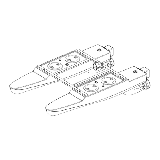
System Overview Diagram Figure 1: Hydrone™ RCV Servo System Overview... -
Page 14: Hydrone™ Rcv Servo Front View
Figure 2: Hydrone™ RCV Servo Front View... -
Page 15: Hydrone™ Rcv Servo Side View
Figure 3: Hydrone™ RCV Servo Side View... -
Page 16: Hydrone™ Rcv Servo Top View
Figure 4: Hydrone™ RCV Servo Top View... -
Page 17: Assembling Your Hydrone™ Rcv Servo
Assembling Your Hydrone™ RCV Servo Hydrone Pontoons: 1. Open the Hydrone™ RCV Servo case. 2. The top section that houses the frame, fins, and other components can be removed and set aside. Figure 5: Opening Hydrone™ RCV Servo Case Figure 6: Removing Top Layer 3. -
Page 18: Port(Left) Pontoon
Figure 7: Port(Left) Pontoon 4. Space the pontoons roughly 1’ (30.4cm) apart. 5. Verify the port pontoon and starboard pontoon are on their correct sides. Figure 8: Left And Right Pontoons • Power switches and Hydrone Stickers should be facing outward •... -
Page 19: Pontoons Not Spaced Correctly
Figure 9: Pontoons Not Spaced Correctly 7. Loosely install all the supplied stainless steel frame hardware. Figure 10: Frame Hardware 8. Tighten them with the supplied 3mm Allen driver. -
Page 20: Frame Attached
Figure 11: Frame Attached 9. Flip the Hydrone™ RCV Servo upside down to gain access to the fin mount channel. 10. Slide the fin with the notch facing the bow into the fin mount channel. 11. Using the supplied 2.5mm Allen driver, tighten the set screw (circled red) to hold the fin in place. Figure 12: Fin Installation 12. -
Page 21: Servo Thruster Installation
Figure 13: Servo Thruster Installation (a) Port Servo Thruster (b) Starboard Servo Thruster Figure 14: Servo Thruster Locations... -
Page 22: Hydrone™ Rcv Servo Assembled
Figure 15: Hydrone™ RCV Servo Assembled... -
Page 23: Hydrone™ Rcv Servo Endurance Chart
Hydrone™ RCV Servo Endurance Chart Figure 16: Hydrone™ RCV Servo Endurance Chart Remote Control Unit (RCU) The Hydrone™ RCV Servo is controlled by a Taranis Q-X7 Access Transmitter. Information Figure 17: RCU Bottom View To charge the battery: • Open bottom dust cover to reveal USB mini port. •... -
Page 24: Rcu Front View
Figure 18: RCU Front View Remote Control Unit Functions Power Press and hold (Not labeled - Release when the fourth loading dot appears - to power on Right below Hook) Release when the last loading dot shows - to power off J1/J2 Throttle (Up/Down) Steering (Left/Right) -
Page 25: Voltage Tester
Figure 19: RCU Back View Voltage Tester Information Max voltage of a 4S battery is 16.8VDC. Connecting to a Voltage Tester: 1. Connect the balance cable connector to the voltage tester. 2. Due to the versatile nature of the voltage tester, it may take a few configurations to connect correctly. -
Page 26: Battery Charging
3. The voltage tester will cycle from overall voltage to each cell voltage. 4. It is recommended to check every battery prior to operation. Battery Charging 3.7.1 E4 Cube Charger Important Alert Never leave batteries unattended while charging. Batteries on charge MUST remain under constant observation so that you may react quickly should any problems arise. -
Page 27: E4 Cube Balance Charger Technical Data
• First LED indicates 25% capacity • Second LED indicates 50% capacity • Third LED indicates 75% capacity • Fourth LED indicates 100% capacity • Four LEDS will always be on when the battery is fully charged 6. When the battery is fully charged, disconnect the AC power first. Then disconnect the LiPo battery. -
Page 28: Optional - Spektrum Charger
3.7.2 Optional - Spektrum Charger Important Alert Never leave batteries unattended while charging. Batteries on charge MUST remain under constant observation so that you may react quickly should any problems arise. Caution Max voltage of a 4S battery is 16.8VDC. Caution Charging LiPo Battery: with Spektrum Charger... -
Page 29: Spektrum Charger Settings
7. Press and release the menu/select button to display the charger settings list. Task Select Charge, Discharge, or Storage Battery (Type) Select LiPo Cells (Cell Count) Select 4 cells for 4S LiPo battery Select 10A for 10,000mAh, 16A for Current 16,000mAh and 20A for 22,000mAh batteries Start... -
Page 30: Pre-Launch Check List
Technical Data Input Voltage 100-240 VAC Charge Current 0.1 - 20.0A Discharge Current 0.1 - 1.5A USB Output 5V / 2A Max Charge Power 2x200W Max Discharge Power 10W Balance Current 1.5A/cell Balance Cells 1-6s Table 9: Spektrum Charger Technical Data Pre-Launch Check List •... -
Page 31: Hydrone™ Rcv Servo Power On Procedure
Hydrone™ RCV Servo Power On Procedure Caution • Disconnect the batteries of the Hydrone™ RCV Servo at 12.8VDC to avoid irreversible damage. (Refer to 1.4) • To extend the battery life of the Hydrone™ RCV Servo, it is advisable to power it off when the voltage reaches 13.6VDC. -
Page 32: Voltage Monitoring
3.13 Voltage Monitoring Hydrone™ RCV Servo has a built-in real-time voltage monitor of the system and RCU. To view RCU battery voltage: 1. Power on the RCU. (Refer to 3.5) 2. Press EXIT to get to the main screen. Figure 24: Main Screen 3. - Page 33 • Why does the thruster motor not respond while the Hydrone™ RCV Servo is powered? Alert tone of beep-, beep- (1 second interval) is heard. – There is no signal from the receiver. Verify that the RCU is powered and that the RCU and receiver are bound.
-
Page 34: Troubleshooting
Troubleshooting Propeller Orientation And Rotation If the propellers on a Hydrone™ RCV Servo are rotating in the wrong direction, it will cause the boat to move in circles when attempting to go forward. Similarly, installing the wrong propeller will also lead to same issue. -
Page 35: Receiver Connections
Figure 28: W30 CW Prop Receiver Connections Hydrone™ RCV Servo Port(Left) Pontoon Receiver: • ESC connected to Channel 1. • Servo Thruster to Channel 3. Figure 29: Channel 1 • Telemetry power cable connected to AIN2. (Figure 36) Figure 30: Receiver AIN2 Connection... -
Page 36: Configure Procedure
Hydrone™ RCV Servo Starboard(Right) Pontoon Receiver: • ESC Connected to Channel 2. • Servo Thruster to Channel 4. Figure 31: Channel 2 • Telemetry power cable connected to AIN2. (Figure 36) Figure 32: Receiver AIN2 Connection Configure Procedure RCU Receiver Binding Procedure Archer Plus R6 Binding: Registration is only required if the RCU or Receiver (RCVR) was replaced. -
Page 37: Model Select Screen
Figure 33: Model Select Screen 4. Quick press ’Page’ to switch to SETUP Page 2/13. Figure 34: Internal RF 5. Using the ENT knob, scroll down to INTERNAL RF. See figure 34. (a) Archer Plus R6 Registration: (Registration ID is the vessel serial number) i. -
Page 38: Rcu Telemetry Configuration Procedure
• It is suggested to disconnect the main cable to remove power and reconnect when power is needed. iii. On the RCU, ’Waiting...’ will be replaced with the model name. iv. Press Enter to confirm, registration complete. v. Power off the receiver. 6. -
Page 39: Telemetry Page
4. Quick press ’Page’ to switch to TELEMETRY Page 12/13. Figure 40: Telemetry Page 5. Scroll down and select ”Delete all sensors”. Figure 41: Delete All Sensors Figure 42: Delete All Sensors Pop-Up 6. Scroll up and select ”Discover new sensors”. Figure 43: Discover New Sensors 7. -
Page 40: Rcu Calibration Procedure
Figure 44: A2 Sensor Page 9. At the top of the screen is the pontoon voltage. 10. Scroll down to the Ratio. Modify the value to set the pontoon voltage. Use the supplied Voltage Checker to check the pontoon voltage. 11. -
Page 41: Esc Calibration Procedure
3. Hold down ’Menu’ button. Figure 47: RCU Settings 4. Quick press ’Page’ to switch to HARDWARE to Page 6/7. Figure 48: Hardware Page 5. Highlight ’Calibration’ and select. 6. Follow the onscreen instructions. Figure 49: Start Of Calibration 7. Once calibration is complete, screen will cycle back to start of calibration page. 8. -
Page 42: Esc Programming Procedure
7. A steady and long beep— can be heard, confirming the neutral position. Figure 50: Joystick Position 8. Finalization tones can be heard. Calibration complete. 9. Repeat for the opposite side. ESC Programming Procedure LED Indications Solid Red Throttle Solid Red and Green Full throttle Flashing Red Low Voltage Cutoff Protection is activated... -
Page 43: Service And Maintenance
2. Connect the ribbon cable to the ESC. Pay attention to the connector orientation. Figure 52: ESC Programming Card Connection 3. Power on the Hydrone™ RCV Servo. The Programming Card will power on. 4. Using the chart below, match the Items with the Values. 5. -
Page 44: Service
Service 7.3.1 Thruster Replacement Servo Thruster Removal: 1. Disconnect the connector from the pontoon bulkhead. 2. Unscrew locking thumbscrew. 3. Slide the servo housing up to remove from mount. Figure 53: Servo Thruster Removal Servo Thruster Installation: 1. Slide the servo housing down into the mount. 2. -
Page 45: Propeller Replacement
7.3.2 Propeller Replacement Caution Use Vibra-tite with all hardware. Plastic may become damaged if Vibra-tite instructions are not properly followed. 1. Remove the Servo Thruster from the pontoon. (Figure 13) 2. Flip over the Servo Thruster to access the back panel. 3. -
Page 46: Servo Thruster Adapter Shaft Removal
8. Remove the 1x screw with a #3 Philips screwdriver. Figure 57: Servo Thruster Adapter Shaft Removal 9. Remove the 4x screws with a #3 Philips driver. Figure 58: Thruster Housing Removal 10. Remove the 2x screws with a #3 Philips driver. -
Page 47: Motor Cleaning
Figure 59: Prop Removal 11. Remove the prop. The prop may be suctioned to the motor housing. Use care when removing. Figure 60: Prop Removed 12. Install the replacement W30 prop. 13. Follow the instructions in reverse order for reassembly. Caution Be careful not to pinch any wires when installing the access panel cover. -
Page 48: Servo Thruster Access Panel
Figure 61: Servo Thruster Access Panel 4. Rotate the thruster to gain access to the thruster shaft bolt. 5. Use a 2mm Allen driver to remove the shaft bolt. Figure 62: Servo Thruster Shaft 6. Slide the thruster shaft out from the housing. 7. -
Page 49: Servo Thruster Adapter Shaft Removal
Figure 63: Servo Thruster Adapter Shaft Removal 9. Remove the 4x screws with a #3 Philips driver. Figure 64: Thruster Housing Removal 10. Remove the 2x screws with a #3 Philips driver. Figure 65: Prop Removal... -
Page 50: Prop Removed
11. Remove the prop. The prop may be suctioned to the motor housing. Use care when removing. Figure 66: Prop Removed 12. Remove the 2x M3 bolts with a 2.5mm Allen Driver Figure 67: Motor Housing Removal 13. Loosen the 2x set screws on the collar towards the bow using a 1.5mm driver(not supplied). -
Page 51: Rotor Removal
Figure 68: Rotor Removal 14. The motor rotor and stator are magnets. To remove, pull on the motor rotor to slide off. Figure 69: Stator And Rotor 15. Inspect the magnets and protective coverings. Clean with mild soap and water. 16. -
Page 52: Rcu Rtc Battery Replacement
7.3.4 RCU RTC Battery Replacement Replace the RTC battery when you receive ”Battery Warning: RTC Battery Low”. Part Required: • CR21220 Coin Battery Tool Required: • Phillips Screwdriver 1. Power off and flip over the RCU. 2. Locate the two visible Phillip screws and unscrew them. Figure 70: RCU 2x Screw Locations 3. -
Page 53: Rcu Final Screw Locations
Figure 71: RCU Final Screw Locations 6. Locate the additional two Phillip screws and unscrew them. 7. Carefully split case of the RCU. Figure 72: RCU RTC Location 8. Locate the RTC battery(circled red) and remove it. 9. Replace it with a new CR1220 battery. -
Page 54: Maintenance Schedule
10. Carefully put the two case halves together. Verify the module bay pins (circled yellow in Figure 72) slide through the slot (Figure 19). 11. Screw in the four Philip screws. 12. Connect the battery. 13. Install battery spacing foam. 14. -
Page 55: Technical Diagrams
Technical Diagrams Beaufort Sea State Chart Estimating Wind Speed and Sea State with Visual Clues Beaufort Wind Wave Wind Speed Visual Clues number Description Height Calm 0 knots 0 feet Sea is like a mirror. Smoke rises vertically. Ripples with the appearance of scales are formed, but without foam crests. Light Air 1-3 kts <... -
Page 56: Block Diagrams
Block Diagrams THRUSTER THRUSTER THRUSTER THRUSTER SERVO SERVO RECEIVER RECEIVER Figure 74: Block Diagram... -
Page 57: Electrical Diagrams
Electrical Diagrams Figure 75: Hydrone™ RCV Servo Electrical Diagram... -
Page 58: Servo Thruster Electrical Diagram
Figure 76: Servo Thruster Electrical Diagram... -
Page 59: Mechanical Diagrams
Mechanical Diagrams Figure 77: Side View Diagram... -
Page 60: Front View Diagram
Figure 78: Front View Diagram... -
Page 61: Top View Diagram
Figure 79: Top View Diagram... - Page 62 Revision History Revision Date Author(s) Description 3.20.2024 Created...
Need help?
Do you have a question about the Hydrone RCV Servo and is the answer not in the manual?
Questions and answers