Table of Contents
Advertisement
Quick Links
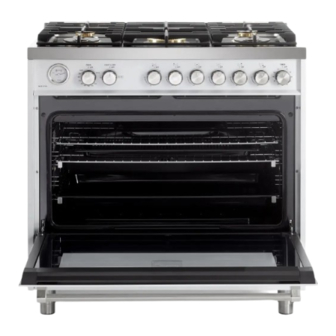
SINGLE OVEN GAS RANGE
VUFSGG365..
Models:
USERS OPERATING INSTRUCTIONS
IMPORTANT - PLEASE READ AND FOLLOW
•
Before beginning, please read these instructions completely and carefully.
•
Do not remove permanently affixed labels, warnings, or plates from the product. This may
void the warranty.
•
Please observe all local and national codes and ordinances.
•
Please ensure that this product is properly grounded.
The installer should leave these instructions with the consumer who should retain
•
for local inspector's use and for future reference.
The electrical plug should always be accessible.
•
Installation must conform with local codes or in the absence of codes, the National Fuel Gas
Code ANSI Z223.1/NFPA 54 - latest edition. Electrical installation must be in accordance
with the National Electrical Code, ANSI/NFPA70 - latest edition and/or local codes. IN
CANADA: Installation must be in accordance with the current CAN/CGA-B149.1 National
Gas Installation Code or CAN/CGA-B149.2, Propane Installation Code and/or local codes.
Electrical installation must be in accordance with the current CSA C22.1 Canadian Electrical
Codes Part 1 and/or local codes.
INSTALLATION IN MANUFACTURED (MOBILE) HOME: The installation must conform
with the Manufactured Home Construction and Safety Standard, Title 24 CFR, Part 3280
[formerly the Federal Standard for Mobile Home Construction and Safety, Title 24, HUD
(Part 280)] or, when such standard is not applicable, the Standard for Manufactured Home
Installations, ANSI/NCSBCS A225.1, or with local codes where applicable.
INSTALLATION IN RECREATIONAL PARK TRAILERS: The installation must conform with
state or other codes or, in the absence of such codes, with the Standard for Recreational
Park Trailers, ANSI A119.5.
Installation of any gas-fired equipment should be made by a Iicensed plumber. A manual
shut-off valve must be installed in an accessible location in the gas line external to the
appliance for the purpose of turning on or shutting off gas to the appliance (In Massachusetts
such shutoff devices should be approved by the Board of State Examiners of Plumbers &
Gas Fitters).
If an external electrical source is utilized, the appliance, when installed, must be electrically
grounded in accordance with local codes or, in the absence of local codes, with the national
Electrical Code, ANSI/NFPA 70.
Some models are supplied with a protective film on steel and aluminum parts.
This film must be removed before installing/using the appliance.
THIS RANGE IS FOR RESIDENTIAL USE ONLY
Advertisement
Table of Contents

Related Manuals for Verona VUFSGG365 Series


Summary of Contents for Verona VUFSGG365 Series
- Page 1 SINGLE OVEN GAS RANGE VUFSGG365.. Models: USERS OPERATING INSTRUCTIONS IMPORTANT - PLEASE READ AND FOLLOW • Before beginning, please read these instructions completely and carefully. • Do not remove permanently affixed labels, warnings, or plates from the product. This may void the warranty.
- Page 2 WARNING See installation instructions for details. Tip-Over Hazard A child or adult can tip the range and be killed. Check installation of anti-tip device per installation Anti-tip bracket instructions. Adjustable bracket Check engagement of anti-tip device if range assembly to be xed to the back of the range is moved per installation.
- Page 3 Dear Customer, Thank you for having purchased and given your preference to our product. The safety precautions and recommendations reported below are for your own safety and that of others. They will also provide a means by which to make full use of the features offered by your appliance. Please preserve this booklet carefully.
-
Page 4: General Information
USER INSTRUCTIONS GENERAL INFORMATION WARNING!! WARNING!! ELECTRICAL GROUNDING INSTRUCTIONS This appliance shall not be used for space heating. This The range must be electrically grounded in accordance with information is based on safety considerations. local codes or, in the absence of local codes, with the National Electrical Code, ANSI/NFPA No. -
Page 5: Important Precautions And Recommendations
IMPORTANT PRECAUTIONS AND RECOMMENDATIONS After having unpacked the appliance, check to ensure that it is not damaged. In case of doubt, do not use it and consult your supplier or a professionally qualified technician. Packing elements (i.e. plastic bags, polystyrene foam, nails, packing straps, etc.) should not be left around within easy reach of children, as these may cause serious injuries. -
Page 6: Cooking Hob
features Island trim fitted 7/8” backguard Backguard fitted 3” backguard WARNING - VERY IMPORTANT NOTICE Never obstruct the slots on the backguard. Fig. 1.1 COOKING HOB Semi-rapid burner (SR) - 8000 BTU/hr Double-ring compact burner (DCC) - 12000 BTU/hr Dual burner (DB) (*) -17000 BTU/hr Inner crown - 2800 BTU/hr Outer crown - 14200 BTU/hr IMPORTANT: The Dual burner is controlled by two separate knobs;... -
Page 7: Controls Description
Fig. 1.2 HIGH °F MEDIUM CONTROLS DESCRIPTION Oven thermometer Gas oven/gas broil control knob Oven light & fan control knob Front left burner control knob Rear left burner control knob Central dual burner control knob (inner crown) Central dual burner control knob (outer crown) Rear right burner control knob Front right burner control knob 10. - Page 8 how to use the top burners GAS BURNERS (Semi-rapid and double-ring compact) Gas flow to the burners is adjusted by turning the knobs (illustrated in fig. 2.1) which control the valves. Turning the knob, so that the indicator line points to the symbols printed on the panel, achieves the following functions: Knob DOUBLE-RING...
- Page 9 LIGHTING GAS BURNERS FITTED WITH FLAME FAILURE SAFETY DEVICE In order to light the burner, you must: 1 – Push and turn the knob in a counterclockwise direction up to the position (maximum rate), push in and hold the knob until the flame has been lit (fig. 2.2). The sparks produced by the lighter situated inside the relative burner will light the flame.
- Page 10 GAS BURNERS (Dual) The Dual Burner is a very flexible burner which allows different regulations for optimal cooking. It is composed by one inner and one outer crown: the inner and outer crown can be used together or separately. The Dual burner is controlled by two separate knobs: •...
- Page 11 Turning the dial so that the symbols printed on the dial point to the mark on the bezel achieves the following functions: DUAL BURNER OPERATION / CONTROL KNOBS Fig. 2.5...
- Page 12 CHOICE OF BURNER (fig. 2.6) The symbols printed on the panel above the gas knobs indicate the correspondence between the knob and the burner. The most suitable burner is to be chosen according to the diameter and volume capacity of the container to be warmed. It is important that the diameter of the pots or pans suitably match the heating potential of the burners in order not to jeopardise the efficiency of the burners, bringing about a waste of gas fuel.
-
Page 13: General Features
how to use the gas oven GENERAL FEATURES Attention: the range becomes very hot during operation. The gas oven is provided with: a) Oven burner, mounted on the lower part of the oven. Attention: oven door becomes very hot during b) Broil burner, mounted on the upper part of the oven. -
Page 14: Oven Burner
COOLING FAN MOTOR This appliance incorporates a safety cooling fan motor to achieve optimum efficiency of the controls, ensure lower surface temperatures are maintained and cool the internal components. The cooling fan motor turns on automatically some minutes after igniting the oven or broil burner. It may run on (for various minutes) even after the oven or broil burner has been turned off. - Page 15 IGNITION OF THE OVEN BURNER IMPORTANT NOTE: during ignition of the oven burner the fan motor shall be switched off (light and fan control knob in position - fig. 3.2). The thermostat allows the automatic control of the temperature. The gas delivery to the oven burner is controlled by a two way thermostatic tap (oven and broil burners) with flame-failure device.
- Page 16 CONVECTION BAKING WITH VENTILATION (OVEN BURNER WITH FAN MOTOR) After lighting the oven burner switch on the fan motor by turning the LIGHT & FAN control knob (fig. 3.2) on position. Before introducing the food, preheat the oven to the desired temperature. For a correct preheating operation, it is advisable to remove the tray from the oven and introduce it together with the food, when the oven has reached the desired temperature.
- Page 17 IGNITION OF THE BROIL BURNER IMPORTANT NOTE: the fan motor cannot be used in combination with the broil burner. A safety device switches off the fan motor when the gas oven/broil control knob is turned on position. The broil burner generates the infra-red rays for broiling. To light the broil burner operate as follow: 1) Open the oven door to the full extent.
- Page 18 Fig. 3.5 BROILING Very important: the broil burner must always be used with the oven door closed. - Position the shelf on the first level from the top (fig. 3.5). - Turn on the broil burner, as explained in the preceding paragraphs and let the broil burner preheat for about 5 minutes with the door closed.
-
Page 19: Minute Counter
120’ alarm knob MINUTE COUNTER (fig. 4.1) The minute counter is a timed acoustic warning device which can be set for a maximum of 120 minutes. The knob (fig. 4.1) must be rotated clockwise as far as the 120 minute position and then set to the required time by rotating it counterclockwise. - Page 20 cleaning and maintenance GENERAL RECOMANDATION WARNING Important: Before any operation of cleaning and maintenance disconnect the • appliance from the electrical supply. • It is advisable to clean when the appliance is cold and especially for cleaning the enamelled parts. •...
- Page 21 BURNERS AND GRIDS • These parts can be removed and cleaned with appropriate products. • After cleaning, the burners and their flame distributors must be well dried and correctly replaced. • It is very important to check that the burner flame distributor and the cap has been correctly positioned - failure to do so can cause serious problems.
- Page 22 DUAL BURNER Fig. 5.5 Fig. 5.4 Note: Continuous use may cause a change in the glaze around the burners and grids, corresponding to the areas exposed to the heat. This is a natural phenomenon and does not prevent the parts from working properly. Fig.
- Page 23 ADVICE FOR USE AND MAINTENANCE OF CATALYTIC PANELS The catalytic panels are covered with special microporous enamel which absorbs and does away with oil and fat splashes during normal baking over 200 °C. If, after cooking very fatty foods, the panels remain dirty, operate the oven “idling” on max temperature for about 30 minutes.
- Page 24 To remove the telescopic sliding shelf supports: Remove the side racks by unscrewing the fixing screws (fig. 5.7a). • • Lay down the sliding shelf support and side racks, with the telescopic sliding shelf support underneath. • Find the safety locks. These are the tabs that clip over the wire of the side rack (arrow “1”...
-
Page 25: Replacing The Oven Lights
REPLACING THE OVEN LIGHTS (NOTE: DEPENDING ON YOUR MODEL, YOUR OVEN MAY ONLY HAVE SOME OF THESE LIGHTS) WARNING: Ensure the appliance is switched off before replacing the lamp to avoid the possibility of electric shock. • Let the oven cavity and the heating elements to cool down. Switch off the electrical supply. -
Page 26: Removing The Storage Drawer
REMOVING THE STORAGE DRAWER Open the drawer completely (fig. 5.11) Move down the lever of left guide (fig. 5.12) and up the lever of right guide WARNING: (fig. 5.13). • Do not remove drawer while hot. Do not remove drawer during Remove the drawer;... -
Page 27: Removing The Oven Door
REMOVING THE OVEN DOOR The oven door can easily be removed as follows: Open the door to the full extent (fig. 5.15). • Open the lever “A” completely on the left and right hinges (fig. 5.16). • Hold the door as shown in fig. 5.17. •... -
Page 28: Do's And Do Not's
DO’S AND DO NOT’S • Do always use the oven with the door closed. • Do always broil with the door closed. • Do read the user instructions carefully before using the range for first time. • Do allow the oven to heat for about two hours, before using for the first time, in order to expel any smell from the new oven insulation, without the introduction of food. - Page 32 The manufacturer cannot be held responsible for possible inaccuracies due to printing or transcription errors in the present booklet. The manufacturer reserves the right to make all modifications to its products deemed necessary for manufacture or commercial reasons at any moment and without prior notice, without jeopardising the essential functional and safety characteristics of the appliances.
Need help?
Do you have a question about the VUFSGG365 Series and is the answer not in the manual?
Questions and answers