
Subscribe to Our Youtube Channel
Related Manuals for Moons' Applied Motion Products TSM23XB-R


Summary of Contents for Moons' Applied Motion Products TSM23XB-R
- Page 1 TSM23XB-R Integrated StepSERVO™ Motor with TruCount™ Absolute Enocder Hardware Manual 920-0154 RevD...
-
Page 2: Table Of Contents
TSM23XB-R Hardware Manual Contents 1 Introduction ................4 1.1 Features .................4 1.2 Block Diagram ...............5 1.3 Safety Instructions ..............6 2 Getting Started ..............7 2.1 Installing Software ..............7 2.2 Mounting the Hardware ............7 2.3 Choosing a Power Supply .............8 2.3.1 Voltage ................... 8 2.3.2 Regeneration Clamp ............... - Page 3 TSM23XB-R Hardware Manual Communicaiton Model RS-485 Modbus/RTU TSM23X2B-R TSM23X3B-R TSM23X4B-R 920-0154 RevD...
-
Page 4: Introduction
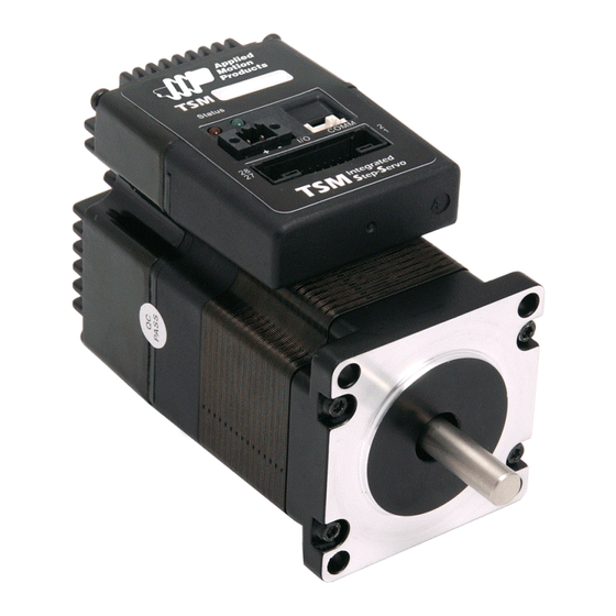
TSM23XB-R Hardware Manual 1 Introduction Thank you for selecting the Applied Motion Products TSM23X Integrated Motor.The TSM line of integrated StepSERVO™ motors combines servo technology with an integrated motor to create a product with exceptional feature and broad capability.TruCount™ Encoders are multi-turn, absolute encoders that don’t require batteries or external power to track encoder position while the motor is powered off. -
Page 5: Block Diagram
TSM23XB-R Hardware Manual 1.2 Block Diagram TSM23X Block Diagram 12 - 70 VDC External 5 Volt DC Power Supply Power Supply RS-232 RXD,+5V,TXD,GND,GND RS-232 or RS-485 RS-485 3.3VDC RX+,RX-,TX+,TX-,GND Internal Voltage Logic Temp Supply Detect +5VDC (100mA max) MOSFET motor Power Amplifier Driver... -
Page 6: Safety Instructions
TSM23XB-R Hardware Manual 1.3 Safety Instructions Only qualified personnel should transport, assemble, install, operate, or maintain this equipment. Properly qualified personnel are persons who are familiar with the transport, assembly, installation, operation, and maintenance of motors, and who meet the appropriate qualifications for their jobs. To minimize the risk of potential safety problems, all applicable local and national codes regulating the installation and operation of equipment should be followed. -
Page 7: Getting Started
TSM23XB-R Hardware Manual 2 Getting Started The following items are needed: • a 12 - 70 Volt DC power supply, see the section below entitled “Choosing a Power Supply” for help in choosing the right one • a small flat blade screwdriver for tightening the connectors (included) •... -
Page 8: Choosing A Power Supply
TSM23XB-R Hardware Manual 2.3 Choosing a Power Supply The main considerations when choosing a power supply are the voltage and current requirements for the application. 2.3.1 Voltage The TSM23X is designed to give optimum performance between 24 and 48 Volts DC. Choosing the voltage depends on the performance needed and motor/drive heating that is acceptable and/ or does not cause a drive over-temperature. -
Page 9: Current
TSM23XB-R Hardware Manual 2.3.3 Current The maximum supply currents required by the TSM23X are shown in the charts below at different power supply voltage inputs. The TSM23X power supply current is lower than the winding currents because it uses switching amplifiers to convert a high voltage and low current into lower voltage and higher current. - Page 10 TSM23XB-R Hardware Manual TSM23X2 70V Power Torque Continuous Boost Supply Current Full Load No Load Speed(RPS) TSM23X3 24V Power Torque Continuous Boost Supply Current Full Load No Load Speed(RPS) TSM23X3 48V Power Torque Continuous Boost Supply Current Full Load No Load Speed(RPS) 920-0154 RevD...
- Page 11 TSM23XB-R Hardware Manual TSM23X3 70V Power Torque Continuous Boost Supply Current Full Load No Load Speed(RPS) 920-0154 RevD...
-
Page 12: Installation/Connections
TSM23XB-R Hardware Manual 3 Installation/Connections 3.1 Connecting the Power Supply Use 16 to 20-gauge wire to connect the TSM23 to a power supply. It contains an internal fuse connected to the “+” terminal that is not user replaceable. If a user serviceable fuse is desired, install a 6.3 amp fast acting fuse in line with the “+”... -
Page 13: Connecting The Tsm23X Communications
TSM23XB-R Hardware Manual 3.2 Connecting the TSM23X Communications 3.2.1 Connecting to a Host using RS-485 RS-485 communication allows connection of more than one drive to a single host PC, PLC, HMI or other computer. It also allows the communication cable to be long (more than 300 meters or 1000 feet). - Page 14 TSM23XB-R Hardware Manual Two-Wire Configuration In a 2-wire system, the host must disable its transmitter before it can receive data. This must be done quickly before a drive begins to answer a query. The TSM23X includes a transmit delay parameter that can be adjusted to compensate for a host that is slow to disable its transmitter. This adjustment can be made over the network using the TD command, or it can be set using the Step- Servo Quick Tuner software.
-
Page 15: Inputs And Outputs
TSM23XB-R Hardware Manual 3.3 Inputs and Outputs The TSM23X has three types of inputs: • High speed digital inputs for step & direction commands or encoder following, 5 to 24 volt logic • Low speed digital input for other signals, 5 to 24 volt logic •... -
Page 16: Step & Dir Digital Inputs
TSM23XB-R Hardware Manual 3.3.2 STEP & DIR Digital Inputs The TSM23 drives include two high-speed inputs: X1/STEP and X2/DIR. They accept 5 to 24 volt single-ended or differential signals, up to 2 MHz. Typically these inputs connect to an external controller that provides step &... -
Page 17: X3/X4/X5/X6 Digital Input
TSM23XB-R Hardware Manual 3.3.3 X3/X4/X5/X6 Digital Input While the STEP and DIR inputs are designed for high-speed digital input operation, the X3/X4/ X5/X6 input are designed for low speed digital input operation between 5 and 24 volts optically Isolated Single-ended input. They can be used with sourcing or sinking signals, 5 to 24 volts. This allows connection to PLCs, sensors, relays and mechanical switches. -
Page 18: X7/X8 Digital Input
TSM23XB-R Hardware Manual 3.3.4 X7/X8 Digital Input The X7/X8 input are designed for low speed digital input operation between 5 and 24 volts optically Isolated differential input. They are normally used for end of travel limit switches. The diagrams below show how to connect the X7/X8 Inputs to various commonly used devices X7/X8+ 5 - 24 volt DC... -
Page 19: Programmable Output Y1/Y2/Y3
TSM23XB-R Hardware Manual 3.3.6 Programmable Output Y1/Y2/Y3 The TSM23X drives feature three optically isolated digital outputs (Y1 to Y3). Y1, Y2 and Y3 share a common terminal YCOM. • Y1 can be set to signal a fault condition. • Y2 can be set to indicate whether the motor is in position(dynamic). •... -
Page 20: Programmable Output Y4
TSM23XB-R Hardware Manual 3.3.7 Programmable Output Y4 TSM23X drives feature one optically isolated digital output Y4. The Y4+(collector) and Y4-(emitter) terminals of the transistor are available at the connector. This allow the output to be configured for current sourcing or sinking. Y4 can be set to provide an output frequency proportional to motor speed (tach signal) or to provide a timing output (50 pulses/rev) or to indicate whether the motor is in position(static) Diagrams of various connection types follow. -
Page 21: Troubleshooting
TSM23XB-R Hardware Manual 4 Troubleshooting LED Error Codes The TSM23X uses red and green LEDs to indicate status. When the motor is enabled, the green LED flashes slowly. When the green LED is solid, the motor is disabled. Errors are indicated by combinations of red and green flashes as shown below. -
Page 22: Reference Materials
TSM23XB-R Hardware Manual 5 Reference Materials 5.1 Torque-Speed Curves Note: all torque curves were measured at 20,000 steps/rev. Note: 5 amp rating is continuous, 7.5 amp rating is boost Continuous TSM23X2 Boost Speed(rps) Continuous TSM23X3 Boost Speed(rps) 920-0154 RevD... -
Page 23: Technical Specifications
TSM23XB-R Hardware Manual 5.2 Technical Specifications Power Amplifier Amplifier Type Dual H-Bridge, 4 Quadrant Current Control 4 state PWM at 20 KHz TSM23X-2 G: Up to 1.0N•m Continuous(1.3 N•m Boost) □ Output Torque TSM23X-3 G: Up to 1.5N•m Continuous(2.0 N•m Boost) □... -
Page 24: Trucount Absolute Encoder Homing Setup
TSM23XB-R Hardware Manual 5.3 TruCount Absolute Encoder Homing Setup The TruCount™ series encoder allows the motor to track the motor shaft position even when power is off. TruCount™ encoder does not need an external battery for encoder position tracking while the motor is power off. For more detail please refer to APPN0052 for details... - Page 25 TSM23XB-R Hardware Manual The basic structure of a command packet from the host to the drive is always a text string followed by a carriage return. The text string is composed of the command itself, followed by any required parameters. A carriage return denotes the end of transmission to the drive. The syntax of the command is XXAB<cr>...
-
Page 26: Optional Accessories
TSM23XB-R Hardware Manual 5.5 Optional Accessories Regeneration Clamp P/N: RC880 28.6 When using a regulated power supply you may encounter a problem with regeneration. The kinetic energy caused by regeneration is transferred back to the power supply. This can trip the overvoltage protection of a switching power supply, causing it to shut down. - Page 27 TSM23XB-R Hardware Manual I/O Cable P/N: 3004-318-2M 920-0154 RevD...
- Page 28 TSM23XB-R Hardware Manual Mating Connectors Legacy Description Model Supplier Description Model Supplier Power RS232 Connector 1615780000 Weidmuller Housing ZER-04V-S Pin, Connector SZE-002T-P0.3 Housing PUDP-28V-S RS-485 & CANOpen Existing Description Model Supplier Description Model Supplier Power RS232 Connector 0225-0602 Dinkle Housing ZER-04V-S Pin, Connector SZE-002T-P0.3...
-
Page 29: Contacting Applied Motion Products
TSM23XB-R Hardware Manual 6 Contacting Applied Motion Products 18645 Madrone Pkwy. Morgan Hill, CA 95037, USA 800-525-1609 | www.applied-motion.com 920-0154 920-0154B RevD 5/1/2020...
Need help?
Do you have a question about the Applied Motion Products TSM23XB-R and is the answer not in the manual?
Questions and answers