Table of Contents
Advertisement
Quick Links
Advertisement
Table of Contents

Subscribe to Our Youtube Channel
Related Manuals for Moons' AMP StepSERVO TSM14POE Series


Summary of Contents for Moons' AMP StepSERVO TSM14POE Series
- Page 1 TSM14POE StepSERVO Integrated Motor Hardware Manual 920-0153 A 01/23/2020...
-
Page 2: Table Of Contents
TSM14POE Hardware Manual 920-0153 A 01/23/2020 Contents 1 Introduction ................4 1.1 Features .................4 1.2 Block Diagram ...............5 1.3 Safety Instructions ..............6 2 Getting Started ..............7 2.1 Installing Software ..............7 2.2 Mounting the Hardware ............7 2.3 Choosing a Power Supply .............8 3.2 Connecting the Drive to Your PC using Ethernet ....9 4 Troubleshooting ..............17 5 Reference Materials ............18... - Page 3 TSM14POE Hardware Manual 920-0153 A 01/23/2020 TSM14POE Models Available Connector Communication Model RJ45 M12 8 Pin X-Coded EtherNet/IP TSM14POE3M-IPEJ TSM14POE3M-IPEM...
-
Page 4: Introduction
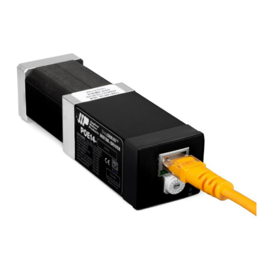
TSM14POE Hardware Manual 920-0153 A 01/23/2020 1 Introduction Thank you for selecting the Applied Motion Products TSM14POE StepSERVO Integrated Motor. The TSM line of integrated step-servo motors combines servo technology with an integrated motor to create a product with exceptional features and broad capability. We hope our commitment to performance, quality and economy will result in a successful motion control project. -
Page 5: Block Diagram
TSM14POE Hardware Manual 920-0153 A 01/23/2020 1.2 Block Diagram TSM14POE 42.5-57 VDC Block Diagram 5 Volt DC Power Supply 3.3VDC Internal Voltage Logic Temp Supply Detect MOSFET motor Power Amplifier 100 Mbit Ethernet Driver Ethernet POE+ power Controller encoder Over Current Detect Status... -
Page 6: Safety Instructions
TSM14POE Hardware Manual 920-0153 A 01/23/2020 1.3 Safety Instructions Only qualified personnel should transport, assemble, install, operate, or maintain this equipment. Properly qualified personnel are persons who are familiar with the transport, assembly, installation, operation, and maintenance of motors, and who meet the appropriate qualifications for their jobs. -
Page 7: Getting Started
TSM14POE Hardware Manual 920-0153 A 01/23/2020 2 Getting Started The following items are needed: • A POE+ rated Ethernet switch or injector. Recommended: - Injector: BV Tech POE-I100G (Applied Motion P/N 1000-382). - Switch: BV Tech POE-SW801. • A PC running Microsoft Windows XP, Vista, or Windows 7 or 8 or 10. 32 or 64 bits. •... -
Page 8: Choosing A Power Supply
TSM14POE Hardware Manual 920-0153 A 01/23/2020 2.3 Choosing a Power Supply Please choose a POE+ (IEEE 802.3at Type 2) compatible injector or powered switch. Modes A and B are supported. Recommended injector: BV Tech POE-I100G (AMP part number 1000-382). Recommended powered Ethernet switch: BV Tech POE-SW801. -
Page 9: Connecting The Drive To Your Pc Using Ethernet
TSM14POE Hardware Manual 920-0153 A 01/23/2020 3.2 Connecting the Drive to Your PC using Ethernet This process requires three steps • Physically connect the drive to your network (or directly to the PC). • Set the drive’s IP address. • Set the appropriate networking properties on your PC. Addresses, Subnets, and Ports Every device on an Ethernet network must have a unique IP address. - Page 10 TSM14POE Hardware Manual 920-0153 A 01/23/2020 Your drive includes a 16 position rotary switch for setting its IP address. The factory default address for each switch setting is shown in the table on the next page. Settings 1 through E can be changed using the Step-Servo Quick Tuner software. Setting 0 is always “10.10.10.10”, the universal recovery address.
- Page 11 TSM14POE Hardware Manual 920-0153 A 01/23/2020 Ports are used to direct traffic to the right application once it gets to the right IP address. The UDP eSCL port in our drives is 7775. To send and receive commands using TCP, use port number 7776.
- Page 12 TSM14POE Hardware Manual 920-0153 A 01/23/2020 Once you’ve chosen an appropriate IP address for your drive, set the rotary switch according the address table above. If none of the default addresses are acceptable for your network, you can enter a new table of IP addresses using Step-Servo Quick Tuner software. If your network uses addresses starting with 192.168.0, the most common subnet, you will want to choose an address from switch settings 4 through E.
- Page 13 TSM14POE Hardware Manual 920-0153 A 01/23/2020 5. If the option “Use the following IP address” is selected, life is good. Change the subnet mask to “255.255.0.0” and click OK. Using DCHP If you want to use your drive on a network where all or most of the devices use dynamic IP addresses supplied by a DHCP server, set the rotary switch to “F”.
- Page 14 TSM14POE Hardware Manual 920-0153 A 01/23/2020 Please select the NIC that you use to connect to the network to which you’ve connected your drive. Then click OK. Drive Discovery will notify you as soon as it has detected a drive. If you think this is the correct drive, click Yes.
- Page 15 TSM14POE Hardware Manual 920-0153 A 01/23/2020 4. You should see an icon for your network interface card (NIC). Right click and select properties. a. Scroll down until you see “Internet Properties (TCP/IP)”. Select this item and click the Properties button. b.
- Page 16 TSM14POE Hardware Manual 920-0153 A 01/23/2020 Option 3: Use Two Network Interface Cards (NICs) This technique allows you to keep your PC connected to your LAN, but keeps the drive off the LAN, preventing possible IP conflicts or excessive traffic. 1.
-
Page 17: Troubleshooting
TSM14POE Hardware Manual 920-0153 A 01/23/2020 4 Troubleshooting LED Error Codes The TSM14POE uses red and green LEDs to indicate status. When the motor is enabled, the green LED flashes slowly. When the green LED is solid, the motor is disabled. Errors are indicated by combinations of red and green flashes as shown below. -
Page 18: Reference Materials
TSM14POE Hardware Manual 920-0153 A 01/23/2020 5 Reference Materials 5.1 Mechanical Outlines TSM14POE3M-IPEJ - RJ45 TSM14POE3M-IPEM - M12... -
Page 19: Technical Specifications
TSM14POE Hardware Manual 920-0153 A 01/23/2020 5.2 Technical Specifications Power Amplifier Amplifier Type Dual H-Bridge, 4 Quadrant 4 state PWM at 20 KHz Current Control Output Torque Up to 27 oz-in continuous, 32 oz-in peak Power Supply POE+ injector or powered switch required Over-voltage, under-voltage, over-temp, motor/wiring shorts (phase-to-phase, phase-to- Protection ground) -
Page 20: Torque-Speed Curves
TSM14POE Hardware Manual 920-0153 A 01/23/2020 5.3 Torque-Speed Curves Note: Torque curves were measured at 4096 steps/rev. TSM14POE Speed-Torque Curve Peak Continuous Peak Continuous rev/sec... - Page 21 TSM14POE Hardware Manual 920-0153 A 01/23/2020 Further reading: 2D outline drawings: RJ45 version: https://www.applied-motion.com/products/stepservo-integrated-motors/ tsm14poe3m-ipej M12 version: https://www.applied-motion.com/products/stepservo-integrated-motors/tsm14poe3m- ipem 3D solid models: RJ45 version: https://www.applied-motion.com/products/stepservo-integrated-motors/ tsm14poe3m-ipej M12 version: https://www.applied-motion.com/products/stepservo-integrated-motors/tsm14poe3m- ipem Communication: Host Command Reference Manual www.applied-motion.com/hcr What is POE? https://www.applied-motion.com/news/2019/10/what-poe Data sheet: https://www.applied-motion.com/sites/default/files/TSM14POE-Integrated-Motor- Datasheet-925-0024B.pdf...
-
Page 22: Contacting Applied Motion Products
TSM14POE Hardware Manual 920-0153 A 01/23/2020 6 Contacting Applied Motion Products 404 Westridge Dr. Watsonville, CA 95076, USA 1-800-525-1609 www.applied-motion.com...
Need help?
Do you have a question about the AMP StepSERVO TSM14POE Series and is the answer not in the manual?
Questions and answers