
Related Manuals for Moons' TSM11 Series


Summary of Contents for Moons' TSM11 Series
- Page 1 TSM11 Integrated Step-Servo Motor Hardware Manual AMP & MOONS’ Automation Rev: 1.0 8/26/2015...
-
Page 2: Table Of Contents
TSM11 Hardware Manual Contents 1 Introduction .................. 4 1.1 Features .....................4 1.2 Block Diagram ...................5 1.3 Safety Instructions ................6 2 Getting Started ................7 2.1 Installing Software ................7 2.2 Mounting Hardware ................7 2.3 Choosing a Power Supply ..............8 2.3.1 Voltage Selection ...................8 2.3.2 Current ....................9 3 Installation/Connections ............ - Page 3 TSM11 Hardware Manual The information in this manual applies to the following products: Communication Model RS-422/485 Modbus/RTU TSM11S-1RM TSM11S-2RM TSM11S-3RM TSM11Q-1RM TSM11Q-2RM TSM11Q-3RM Rev. 1.0 8/26/2015...
-
Page 4: Introduction
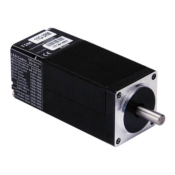
TSM11 Hardware Manual 1 Introduction Thank you for selecting the MOONS’ TSM11 Integrated Motor. The Step-Servo is an innovative revolution for the world of stepper motor, it enhances the stepper motors with servo technology to create a product with exceptional feature and broad capability. TSM is MOONS’ 3rd generation integrated Step-Servo and compact motor+drive+encoder+controller all-in-one solution. -
Page 5: Block Diagram
TSM11 Hardware Manual 1.2 Block Diagram 15-30VDC(24VDC nominal) Voltage Voltage Voltage Temp. Regulator Regulator Det. 3.3V X1/STEP MOSFET Control X2/DIR Software Signal Power Filter X3/EN Input Amplifier X4/AR Current Det. Y1/Out1 Output Motor Y2/Out2 Encoder RS-422/485:TX+,TX- RS485 RX+,RX- Status TSM11 Block Diagram I/O Configurations X1(5-24Volts) X2(5-24Volts) -
Page 6: Safety Instructions
TSM11 Hardware Manual 1.3 Safety Instructions Only qualified personnel should transport, assemble, install, operate, or maintain this equipment. Properly qualified personnel are persons who are familiar with the transport, assembly, installation, operation, and maintenance of motors, and who meet the appropriate qualifications for their jobs. To minimize the risk of potential safety problems, all applicable local and national codes regulating the installation and operation of equipment should be followed. -
Page 7: Getting Started
TSM11 Hardware Manual 2 Getting Started The following items are needed: • A 15-30 volt DC power supply (24VDC is recommended), “Choosing a Power Supply” for help in choosing the right one • Download Step-Servo Quick Tuner software from MOONS’ website •... -
Page 8: Choosing A Power Supply
TSM11 Hardware Manual 2.3 Choosing a Power Supply The main considerations when choosing a power supply are the voltage and current requirements for the application. 2.3.1 Voltage Selection The TSM11 is designed to give optimum performance at 24 VDC . The extended range of operation can be as low as 14VDC minimum and as high as 32 VDC maximum. -
Page 9: Current
TSM11 Hardware Manual 2.3.2 Current The power supply current required by the TSM11 at 24VDC input is shown in the charts below. Note that the supply current flowing into the TSM11 is less than the motor phase current. That’s because TSM11’s switching amplifier converts high voltage and low current from the DC power supply into the higher current and lower voltage required by the motor. -
Page 10: Installation/Connections
TSM11 Hardware Manual 3 Installation/Connections 3.1 Connecting the Power Supply Connect the power supply “+” terminal to the drive “+” terminal and the power supply “-” terminal to the drive “-” terminal using AWG 26 wire. The TSM11 contains an internal fuse connected to the “+”... -
Page 11: Connecting The Tsm11 Communications
TSM11 Hardware Manual 3.2 Connecting the TSM11 Communications The TSM11 is available with RS-422/485 serial communication. Below are descriptions of how to interface RS-422/485 to a PC. 3.2.1 Connecting to a host using RS-422/485 RS-422/485 communication allows connection of more than one drive to a single host PC, PLC, HMI or other computer. - Page 12 TSM11 Hardware Manual RS-232 to RS-422/485 4-wire Converter: • UT-202 is a recommended ‘RS-232 to RS-422’ converter from UTEK TECHNOLOGY (SHENZHEN) CO, LTD. (http://www.szutek.cn/) The connection is as follows. It only supports to establish the full-duplex (4-wire) RS-422 network. It can’t be used in the half-duplex (2-wire) RS-485 network.
-
Page 13: Assigning Addresses
TSM11 Hardware Manual RS-232 to RS-422/485 2-wire Converter: • UT-201 is a recommended ‘RS-232 to RS-485’ converter from UTEK TECHNOLOGY (SHENZHEN) CO, LTD. (http://www.szutek.cn/) The connection is as follows. It only supports to establish the half-duplex (2-wire) RS-485 network. It can’t be used in the full-duplex (4-wire) RS-422 network. -
Page 14: Inputs And Outputs
TSM11 Hardware Manual 3.3 Inputs and Outputs The TSM11 has four high speed (1 MHz) digital inputs, 5 to 24VDC logic: X1/Step can be used as Step, CW Step, A Quadrature, CW Limit, CW Jog, Run/Stop or general purpose input X2/Direction can be used as Direction, CCW Step, B Quadrature, CCW Limit , CCW Jog or general purpose input X3/Enable can be used as Enable, general purpose input... -
Page 15: X1/Step & X2/Dir Digital Inputs
TSM11 Hardware Manual 3.3.2 X1/Step & X2/Dir Digital Inputs The diagram below shows how to connect the X1/Step & X2/Dir Inputs to commonly used device. Note: X1/Step & X2/Dir inputs have been pulled up to power supply input +, typ. 24 VDC Note: If the input voltage is between 5-24 VDC, or the input is not connected, the logic state of that input is HIGH. - Page 16 TSM11 Hardware Manual Connecting to NPN type Proximity Sensor Note: PNP type Proximity Sensor is not compatible to inputs X1/Step and X2/Dir DIR+ X2/Dir DIR- Controller with STEP+ X1/Step TSM11 Differential STEP- Outputs Connecting to Controller with Differential Outputs X1/Step Master X2/Dir TSM11...
-
Page 17: X3/En & X4/Ar Digital Inputs
TSM11 Hardware Manual 3.3.3 X3/EN & X4/AR Digital Inputs The diagram below shows how to connect the X3/En & X4/AR Inputs to commonly used device. Note: X3/En & X4/AR inputs have been internally pulled up to logical supply +3.3 VDC Note: If the input voltage is between 5-24 VDC, or the input is not connected, the logic state of that input is HIGH. -
Page 18: Programmable Output
TSM11 Hardware Manual 3.3.4 Programmable Output The TSM11 has two digital outputs: Inside drive Y1/Out1 Y1/FAULT can be used as fault output or general purpose output. Y2/Out2 Y2/BRAKE can be use as brake, in position, tach out or general purpose output. Diagrams of various connection types as follows: Note: Do not connect the output to more than 30 volts. -
Page 19: Reference Materials
TSM11 Hardware Manual 4 Reference Materials 4.1 Mechanical Outlines (Unit:mm) 4-M2.5 23±0.1 Depth 2.5 Min 4.5±0.1 φ22-0.052 φ5-0.012 Model “L” □ TSM11 -1RM 43.8 □ TSM11 -2RM 52.9 □ 64.1 TSM11 -3RM Rev. 1.0 8/26/2015... -
Page 20: Technical Specifications
TSM11 Hardware Manual 4.2 Technical Specifications Power Amplifier Amplifier Type Dual H-Bridge, 4 Quadrant Current Control 4 state PWM at 20 KHz TSM11□-1RM up to 65 mN.m Output Torque TSM11□-2RM up to 80 mN.m TSM11□-3RM up to 125 mN.m Power Supply External 24 VDC power supply required Input Voltage Range 15 - 30 VDC min/max (nominal 24 VDC) -
Page 21: Torque Speed Curves
TSM11 Hardware Manual 4.3 Torque Speed Curves Note: all torque curves were measured at 20,000 steps/rev. □ Continuous TSM11 -1RM Boost Speed(rps) □ Continuous TSM11 -2RM Boost Speed(rps) □ TSM11 -3RM Continuous Boost Speed(rps) Rev. 1.0 8/26/2015... -
Page 22: Drive/Motor Heating
TSM11 Hardware Manual 4.4 Drive/Motor Heating Step motors convert electrical power from the driver into mechanical power to move a load. Because step motors are not 100% efficient, some of the electrical power turns into heat as it passes through the motor. The amount of heating is not so much dependent on the load being driven as on the motor speed and power supply voltage. -
Page 23: Troubleshooting
TSM11 Hardware Manual 5 Troubleshooting LED Error Codes The TSM11 uses bi-color LED to indicate status. When the motor is enabled, the green LED flashes slowly. When the green LED is solid, the motor is disabled. Errors are indicated by combinations of red and green flashes as follows: LEDs Green - Power... -
Page 24: Mating Connectors And Accessories
TSM11 Hardware Manual 6 Mating Connectors and Accessories 6.1 Mating Cable (included in package) 300±20mm Connector Vendor: JST Housing:GHR-12V-S Crimp:SSHL-002T-P0.2 UL1061 26AWG Mating Connector Diagram Pin No. Green/ Blue/ Color Purple Orange White Brown Yellow Gray Green Blue Black White White Define This cable is for power, I/O and communication connection, included in package. -
Page 25: Contacting Moons
TSM11 Hardware Manual 7 Contacting MOONS’ Service Center +86-400-820-9661 MOONS’Headquarter Ningbo Room 309, Tower B, Taifu Plaza, 565 Jiangjia Road, 168 Mingjia Road, Minhang District, Shanghai 201107, Jiangdong District, Ningbo, 315040, P.R. China P.R. China Tel: +86 (0)574 87052739 Tel: +86 (0)21 52634688 Fax:+86 (0)574 87052365 Fax:+86 (0)21 52634098 Guangzhou...
Need help?
Do you have a question about the TSM11 Series and is the answer not in the manual?
Questions and answers