
Related Manuals for Moons' TSM23C


Summary of Contents for Moons' TSM23C
- Page 1 TSM23C Integrated Step-Servo Motor Hardware Manual Rev. 1.0 AMP & MOONS’ Automation...
-
Page 2: Table Of Contents
2.3.2 Regeneration Clamp ................7 2.3.3 Current ....................8 3 Installation/Connections ............11 3.1 Connecting the Power Supply ............11 3.2 Connecting the TSM23C Communications ........12 3.2.1 Node ID .....................13 3.2.2 Setting the Bitrate .................13 3.3 Inputs and Outputs ................14 3.3.1 Connector Pin Diagram ................14 3.3.2 X1 &... -
Page 3: Introduction
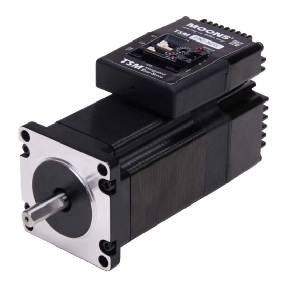
TSM23C Hardware Manual 1 Introduction Thank you for selecting the MOONS’ TSM23C Integrated Motor.The TSM line of integrated step-servo motors combines servo technology with an integrated motor to create a product with exceptional feature and broad capability. We hope our commitment to performance, quality and economy will result in a successful motion control project. -
Page 4: Block Diagram
TSM23C Hardware Manual 1.2 Block Diagram TSM23C Block Diagram 12 - 70 VDC External 5 Volt DC Power Supply Power Supply RS-232 RXD,+5V,TXD,GND,GND RS-232 & CANopen CANopen 3.3VDC CANH, CANL, GND Internal Voltage Logic Temp Supply Detect +5VDC (100mA max) -
Page 5: Safety Instructions
TSM23C Hardware Manual 1.3 Safety Instructions Only qualified personnel should transport, assemble, install, operate, or maintain this equipment. Properly qualified personnel are persons who are familiar with the transport, assembly, installation, operation, and maintenance of motors, and who meet the appropriate qualifications for their jobs. -
Page 6: Getting Started
2.2 Mounting the Hardware As with any step motor, the TSM23C must be mounted so as to provide maximum heat sinking and airflow. Keep enough space around the Integrated Motor to allow for airflow. •... -
Page 7: Choosing A Power Supply
2.3.1 Voltage The TSM23C is designed to give optimum performance between 24 and 48 Volts DC. Choosing the voltage depends on the performance needed and motor/drive heating that is acceptable and/ or does not cause a drive over-temperature. Higher voltages will give higher speed performance but will cause the TSM23C to produce higher temperatures. -
Page 8: Current
TSM23C Hardware Manual 2.3.3 Current The maximum supply currents required by the TSM23C are shown in the charts below at different power supply voltage inputs. The TSM23C power supply current is lower than the winding currents because it uses switching amplifiers to convert a high voltage and low current into lower voltage and higher current. - Page 9 TSM23C Hardware Manual TSM23C-2CG 70V Power Torque Continuous Boost Supply Current Full Load No Load Speed(RPS) TSM23C-3CG 24V Power Torque Continuous Boost Supply Current Full Load No Load Speed(RPS) TSM23C-3CG 48V Power Torque Continuous Boost Supply Current Full Load No Load Speed(RPS) Rev.
- Page 10 TSM23C Hardware Manual TSM23C-3CG 70V Power Torque Continuous Boost Supply Current Full Load No Load Speed(RPS) Rev. 1.0 +86-400-820-9661 0006302013...
-
Page 11: Installation/Connections
3.1 Connecting the Power Supply Use 16 to 20-gauge wire to connect the TSM23C to a power supply. It contains an internal fuse connected to the “+” terminal that is not user replaceable. If a user serviceable fuse is desired, install a 6.3 amp fast acting fuse in line with the “+”... -
Page 12: Connecting The Tsm23C Communications
PC. Plug the 5-pin crimp style connector into one of the two appropriate connector on the TSM23C. Secure the cable to the PC with the screws on the DB9 connector. -
Page 13: Node Id
TSM23C Hardware Manual 3.2.1 Node ID Each node ID on a CANopen network must have a unique Node ID. The Node ID is configured using a sixteen position switch in the front of the drive to set the lower four bits of the Node ID while the upper three bits are configured by using Step-Servo Quick tuner software. -
Page 14: Inputs And Outputs
TSM23C Hardware Manual 3.3 Inputs and Outputs All drives include 8 digital inputs: • X1 & X2 are digital inputs for differential or single-ended signal. They are general purpose inputs • X3 & X4 are software programmable single-ended inputs and can be used for Motor Enable/ Disable and Alarm/Fault Reset function input;... -
Page 15: X1 & X2 Digital Input
TSM23C Hardware Manual 3.3.2 X1 & X2 Digital Input The TSM23C drives include two inputs: X1 and X2. They accept 5 to 24 volt single-ended or differential signals. The diagrams below show how to connect them to various commonly used devices. -
Page 16: X3/X4/X5/X6 Digital Input
TSM23C Hardware Manual 3.3.3 X3/X4/X5/X6 Digital Input X3/X4/X5/X6 input are optically Isolated Single-ended input. They can be used with sourcing or sinking signals, 5 to 24 volts. This allows connection to PLCs, sensors, relays and mechanical switches. Because the input circuits are isolated, they require a source of power. If you are connecting to a PLC, you should be able to get power from the PLC power supply. -
Page 17: X7/X8 Digital Input
TSM23C Hardware Manual 3.3.4 X7/X8 Digital Input The X7/X8 input are optically Isolated differential input. They are normally used for end of travel limit switches.The diagrams below show how to connect the X7/X8 Inputs to various commonly used devices. X7/X8+... -
Page 18: Programmable Output Y1/Y2/Y3
TSM23C Hardware Manual 3.3.5 Programmable Output Y1/Y2/Y3 TSM23C motors feature three optically isolated digital outputs (Y1/Y2/Y3) with common ground. They can be configured by Step-Servo Quick Tuner software. • Y1 can be set to signal a fault condition; • Y2 can be set to indicate whether the motor is in position(dynamic);... -
Page 19: Programmable Output Y4
TSM23C Hardware Manual 3.3.6 Programmable Output Y4 TSM23C motors feature one optically isolated digital output Y4. The Y4+ (collector) and Y4- (emitter) terminals of the transistor are available at the connector. This allows the output to be configured for current sourcing or sinking. -
Page 20: Troubleshooting
4 Troubleshooting LED Error Codes The TSM23C uses red and green LEDs to indicate status. When the motor is enabled, the green LED flashes slowly. When the green LED is solid, the motor is disabled. Errors are indicated by combinations of red and green flashes as shown below. This feature can be disabled for certain warnings but not for alarms. -
Page 21: Reference Materials
TSM23C Hardware Manual 5 Reference Materials 5.1 Torque-Speed Curves Note: all torque curves were measured at 20,000 steps/rev. Note: 5 amp rating is continuous, 7.5 amp rating is boost Continuous TSM23C-2CG Boost Speed(rps) Continuous TSM23C-3CG Boost Speed(rps) Rev. 1.0 +86-400-820-9661... -
Page 22: Mechanical Outlines
TSM23C Hardware Manual 5.2 Mechanical Outlines 56.2 47.14 4-Ø5.1 Ø38.1 70.6 Unit:mm Model Length (L) TSM23C-2CG 95.6 TSM23C-3CG 117.6 Rev. 1.0 +86-400-820-9661 0006302013... -
Page 23: Technical Specifications
Amplifier Type Dual H-Bridge, 4 Quadrant Current Control 4 state PWM at 20 KHz TSM23C-2CG: Up to 1.0N•m Continuous(1.3 N•m Boost) Output Torque TSM23C-3CG: Up to 1.5N•m Continuous(2.0 N•m Boost) Power Supply External 12 - 70 VDC power supply required... -
Page 24: Contacting Moons
TSM23C Hardware Manual 6 Contacting MOONS’ Service Center +86-400-820-9661 Headquarters No. 168 Mingjia Road Industrial Park North Minhang District Shanghai 201107, P.R. China Tel: +86(0)21-52634688 Fax: +86(0)21-62968682 E-mail: info@moons.com.cn MOONS' Industries (America), Inc. 1113 North Prospect Avenue,Itasca, IL 60143 U.S.A.
Need help?
Do you have a question about the TSM23C and is the answer not in the manual?
Questions and answers