
Related Manuals for Moons' TSM23X-EC


Summary of Contents for Moons' TSM23X-EC
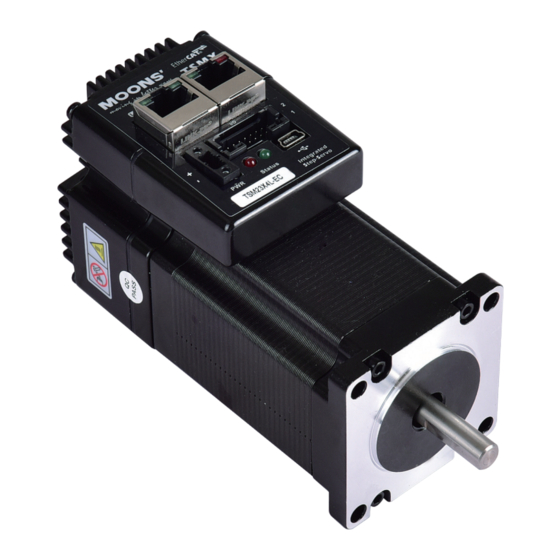
- Page 1 TSM23X-EC Integrated Step-Servo Motor Hardware Manual TSM23X2L-EC / TSM23X3L-EC / TSM23X4L-EC AMP & MOONS’ Automation...
-
Page 2: Table Of Contents
TSM23X Hardware Manual Contents 1 Introduction ....................... 3 1.1 Features ....................3 1.2 Safety Instructions .................. 4 2 Getting Started ....................5 2.1 Choose suitable power supply ............... 5 2.1.1 Voltage Selection ..............5 2.1.1 Current Selection ..............6 2.2 Connecting the Power Supply ..............10 2.3 Installing Software .................. -
Page 3: Introduction
The TSM23X series integrated stepper servo motor perfectly integrates servo control technology to revolutionize the creation of a new closed-loop stepper servo motor with excellent performance and stability.TSM23X-EC is the Ethercat communication version of the series. Support CIA402 communication protocol. -
Page 4: Safety Instructions
TSM23X Hardware Manual 1.2 Safety Instructions • Only qualified personnel should transport, assemble, install, operate, or maintain this equipment. Properly qualified personnel are persons who are familiar with the transport, assembly, installation, operation, and maintenance of motors, and who meet the appropriate qualifications for their jobs. -
Page 5: Getting Started
TSM23X Hardware Manual 2 Getting Started The following items are needed: • A 12-70 volt DC power supply,“Choosing a Power Supply” for help in choosing the right one • A PC running Windows 7 or later • A USB cable (with a USB-MINI-B port) 2.1 Choose suitable power supply The main considerations when choosing a power supply are the voltage and current requirements for the application. -
Page 6: Current Selection
TSM23X Hardware Manual 2.1.1 Current Selection The power supply current required by the TSM23X at different voltages input is shown in the charts below.Note that the supply current flowing into the TSM11 is less than the motor phase current. That’s because TSM11’s switching amplifier converts high voltage and low current from the DC power supply into the higher current and lower voltage required by the motor. - Page 7 TSM23X Hardware Manual TSM23X2L-EC 70V Power Supply Current Torque Continuous Boost Supply Current Full Load No Load Speed(RPS) TSM23X3L-EC 24V Power Supply Current Torque Continuous Boost Supply Current Full Load No Load Speed(RPS) TSM23X3L-EC 48V Power Supply Current Torque Continuous Boost Supply Current Full Load...
- Page 8 TSM23X Hardware Manual TSM23X3L-EC 70V Power Supply Current Torque Continuous Boost Supply Current Full Load No Load Speed(RPS) TSM23X4L-EC 24V Power Supply Current Torque Continuous Boost Supply Current Full Load No Load Speed(RPS) TSM23X4L-EC 48V Power Supply Current Torque Continuous Boost Supply Current Full Load...
- Page 9 TSM23X Hardware Manual TSM23X4L-EC 70V Power Supply Current Torque Continuous Boost Supply Current Full Load No Load Speed(RPS) Rev. 1.0 400-820-9661 08/24/2023...
-
Page 10: Connecting The Power Supply
TSMX 2.3 Installing Software The TSM23X-EC motor package software is Stepper suite, which is a PC-based debugging software that can be used to configure, debug, motion simulation and set the operating mode of the motor. The software is powerful and the interface is easy to operate. -
Page 11: Connect Ethercat
2.4.2 EtherCAT Status Indicator Light The indicator light is used to display the status of EtherCAT. TSM23X-EC has two Link/Activity lights (one for each RJ-45 connector) and two status lights (RUN and ERR) . -
Page 12: Inputs And Outputs
TSM23X Hardware Manual 3 Inputs and Outputs The TSM23X has six digital inputs, three digital outputs and one analog input: 3.1 Connection port block diagram XCOM DGND YCOM Name Name XCOM DGND YCOM Rev. 1.0 400-820-9661 08/24/2023... -
Page 13: X3/X4/X7/X8 Digital Input
TSM23X Hardware Manual 3.2 X3/X4/X7/X8 digital input TSM23X integrated motor x 3, X 4, X 7, x 8 ports can receive a range of 5-24V differential or single- ended digital input signal, they are universal input. X3, X4: limit signal input; general input X7: General Signal Port;... -
Page 14: X5/X6 Digital Inputs
TSM23X Hardware Manual 3.3 X5/X6 digital inputs X 5, X 6 ports can receive 5-24V level of single-terminal digital signal input, through the“COM” port can achieve a common-negative or common-positive method. By setting up the Stepper Suite Software, the X5/X6/X7/X8 port can be configured to function accordingly. The following diagram lists the common wiring methods for X 5 and x 6: X4/X7/X8+ XCOM... -
Page 15: Programmable Output Y1/Y2/Y3
X3/X4/X7/X8+ TSM23X Hardware Manual 5 - 24V 5 - 24V TSM23X Power Supply Power Su NPN type output output X3/X4/X7/X8- 3.4 Programmable output Y1/Y2/Y3 Connecting a NPN type output to an input TSM23X has 3-way photoelectric isolation of single-terminal output signal y 1/y 2/y 3. These three output signals are negatively grounded (YCOM) . -
Page 16: Analog Input
TSM23X TSM23X Hardware Manual YCOM Connecting a sourcing output to PLC's input 3.5 Analog input TSM23X-EC motor has a analog signal input, input voltage range of 0-5V. +5V OUT Ω TSM23X 1 - 10k External potentiometer as analog input 4 Install the motor Any type of TSM23X integrated stepping servo motor must be installed in an environment with good heat dissipation and air circulation. -
Page 17: Troubleshooting
TSM23X Hardware Manual 5 Troubleshooting LED Error Codes The TSM23X driver displays the status with two (red/green) LED lights. The normal state is green LED flashing. If the Red LED blinks, an alarm or an error occurs. The error code is represented by a flashing combination of red and green lights, as shown below. -
Page 18: Mechanical Outlines
TSM23X Hardware Manual 6 Mechanical Outlines 6.1 Technical Specifications Power Amplifier Amplifier Type Dual H-Bridge, 4 Quadrant Current Contro 4 state PWM at 20 KHz TSM23X-2L-EC:Maimum 1.0 N•m continuous runs (1.3N m short runs) Output Torque TSM23X-3L-EC:Maimum 1.5 N•m continuous runs (2.0N m short runs) TSM23X-4L-EC:Maimum 2.4 N•m continuous runs (3.25N m short runs) Input voltage range 18-75 VDC... -
Page 19: Dimensions
TSM23X Hardware Manual 6.2 Dimensions L±1.5 24±0.5 20±0.2 +0.3 4X 5 +0.1 47.14±0.2 57 Max 1.6±0.2 Unit:mm Model TSM23X-2L-EC 95.1 24.5 TSM23X-3L-EC 117.1 46.5 TSM23X-4L-EC 120.1 49.5 Rev. 1.0 400-820-9661 08/24/2023... -
Page 20: Accessories
TSM23X Hardware Manual 7 Accessories 7.1 Regeneration Clamp Type:RC880 Regenerationcan be solved with the use of a MOONS’ RC880 Regeneration Clamp. It is recommended that an RC880 initially be installed in an application. If the “regen” LED on the RC880 never flashes, the clamp is not necessary. 28.6 Unit:mm 7.2 USB mini-b communication cable... -
Page 21: Contacting Moons
TSM23X Hardware Manual 8 Contacting MOONS’ Customer Service Center 400-820-9661 MOONS’ Headquarter North America Company MOONS' Industries (AMERICA), Inc. (Chicago) 168 Mingjia Road, Minhang District, Shanghai 201107, P.R. China 1113 North Prospect Avenue, Itasca, IL 60143,USA MOONS’ Taicang MOONS’ INDUSTRIES (AMERICA), INC. (Boston) No.
Need help?
Do you have a question about the TSM23X-EC and is the answer not in the manual?
Questions and answers