Table of Contents
Advertisement
Available languages
Available languages
Quick Links
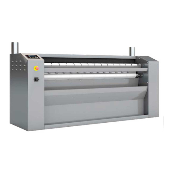
FLATWORK IRONERS
CALANDRAS
SÉCHEUSES-REPASSEUSES
STANDWÄSCHEMANGELN
CALANDRE COMPATTE
CALANDRAS
Плоские утюги
INSTRUCTION MANUAL
MANUAL DE INSTRUCCIONES
MANUEL D'UTILISATION
BEDIENUNGSANLEITUNG
MANUALE DI ISTRUZIONI
MANUAL DE INSTRUÇÕES
РУКОВОДСТВО ПОЛЬЗОВАТЕЛЯ
PS-35/140 M
PS-35/160 M
PS-35/200 M
12314875
01/09/2022
Advertisement
Chapters
Table of Contents

Related Manuals for Fagor PS-35/140


Summary of Contents for Fagor PS-35/140
- Page 1 INSTRUCTION MANUAL MANUAL DE INSTRUCCIONES MANUEL D’UTILISATION BEDIENUNGSANLEITUNG MANUALE DI ISTRUZIONI MANUAL DE INSTRUÇÕES РУКОВОДСТВО ПОЛЬЗОВАТЕЛЯ FLATWORK IRONERS PS-35/140 M CALANDRAS SÉCHEUSES-REPASSEUSES PS-35/160 M STANDWÄSCHEMANGELN PS-35/200 M CALANDRE COMPATTE CALANDRAS Плоские утюги 12314875 01/09/2022...
- Page 2 INTRODUCTION Dear customer, Thank you for the confidence you have placed in our product. We hope it meets your needs. The guarantee does not cover damage to glass components, or consumables (seals, bulbs, etc.) nor damage to insulation material or damage due to the incorrect installation of the appliance, or to inappropriate use, inadequate maintenance or poor repair processes.
- Page 3 EINLEITUNG Sehr geehrter Kunde, vielen Dank für das in unser Produkt gesetzte Vertrauen. Wir hoffen, dass dieses Ihren Vorstellungen voll und ganz gerecht wird. Die Garantiebestimmungen decken keine Schäden an Bauteilen aus Glas oder an Verschleißteilen (Dichtungen, Glühbirnen, usw.) oder Beschädigungen des Isoliermaterials, sowie auf eine nicht ordnungsgemäße Installation des Gerätes, unsachgemäßen Gebrauch oder mangelhafte Reparaturen zurückzuführende Schäden.
- Page 5 INSTRUCTION MANUAL FLATWORK IRONERS PS-35/140 M PS-35/160 M PS-35/200 M 12314875 01/09/2022...
- Page 6 Modèle, Model, Modelo PS-20/140 M E, PS-20/160 M E, PS-20/200 M E PS-35/140 M G, PS-35/160 M G, PS-35/200 M G, PS-35/140 M E, PS-35/160 M E, PS-35/200 M E PS-35/200 M PLUS E, PS-35/260 M PLUS E, PS-35/330 M PLUS E PS-35/200 M PLUS GR, PS-35/260 M PLUS GR, PS-35/330 M PLUS GR Nous déclarons sous notre responsabilité...
- Page 7 Technical documents contain confidential information. Please remember that it is prohibited to disclose and copy these documents and that we will initiate proceedings against the authors of such copies. Processing electric and electronic appliances at the end of their service life When this symbol features on the product or its packaging, it indicates that the product should not be processed with household refuse.
-
Page 8: Table Of Contents
CONTENTS GENERAL PRINCIPLE 1.1 Introduction..............................3 1.2 Operating principle............................4 1.3 Safety ................................. 5 1.3.1 Finger protection safety ........................5 1.3.2 Handle safety ............................5 1.3.3 Heating-related safety ......................... 5 1.4 Heating ............................... 6 1.5 Options ............................... .6 TECHNICAL INSTALLATION INSTRUCTIONS 2.1 Identification plate ............................ -
Page 9: General Principle
1. GENERAL PRINCIPLE 1.1. Introduction Thank you for your trust in purchasing this product. We hope it will meet your needs. The warranty does not cover glass components or consumables (gaskets, light bulbs, textile, etc.), nor damage to insulating materials or damage resulting from the incorrect installation or inappropriate use of the appliance, insufficient maintenance or poor general condition. -
Page 10: Operating Principle
1.2. Operating principle This type of machine is designed to only dry and iron flat laundry items such as sheets or tablecloths. By laying the laundry flat on the infeed table at the front of the machine, the laundry is automatically fed to the drying cylinder by the infeed belts. -
Page 11: Safety
Machine Type PS-35/140 PS-35/160 PS-35/200 Theoretical production (kg/h) electric heating 15-20 25-30 35-40 Theoretical production (kg/h) GAS heating 15-20 25-30 35-40 Cylinder Ø (mm) Working width (mm) 1400 1600 2000 Working speed (m/min) 1.5 - 10 1.5 - 10 1.5 - 10... -
Page 12: Heating
There are several available heating modes: Electric heating: provided by shielded heating elements (variable number of elements • depending on the machine type) placed inside the cylinder. Machine Type PS-35/140 PS-35/160 PS-35/200 Number of heating elements Heating element power (KW) TOTAL power (KW) 16.2... -
Page 13: Technical Installation Instructions
2. TECHNICAL INSTALLATION INSTRUCTIONS 2.1. Identification plate The identification plate on this appliance is located on the left panel. It indicates: The machine type and serial number Electric specifications (Voltage, power, protection) Total power GAS specifications (GAS type, pressure ...) Location of the identification plate 2.2. - Page 14 Sufficient space must be left at the front for operators to be able to work properly and safely. Minimum floor strength is required to install this type of machine (see table below). Machine Type PS-35/140 PS-35/160 PS-35/200 Weight (KG) Floor surface area (m²) 1.34 1.51 1.75...
-
Page 15: Installation
2.2.3. Installation Before removing the transport elements (pallet and beams), bring the machine as close as possible to its final installation. The drier-ironer is delivered on a pallet which is fixed to the 4 corners of the machine by 4 screws. - Page 16 The perfect horizontal and vertical levelling of the machine is imperative for proper operation. If necessary, add blocks under the machine. If the machine is not level, it will cause the ironing bands to move to the side (left or right), thereby significantly increasing their wear 2.2.4 Connection to the electricity supply The electricity supply cable is not included.
- Page 17 The power cable must be connected to the cut-off switch in the left frame. The power supply cable must pass through the back of the machine through one of the holes in the frame as shown above. ELECTRIC heating (E) PS-35/140 PS-35/160 PS-35/200 Motor power (KW) 0.52...
-
Page 18: Gas Connection
2.2.5 GAS connection (gas heating machine only) Before connecting the GAS to the machine, check the identification plate on the machine to find out the type of GAS to be connected to the machine. The machine is always delivered and set up to run on natural GAS, however it is possible to easily convert it during installation to run on propane GAS. - Page 19 II2Esi3P 37/50 Luxembourg (LU) II2E3P NETHERLANDS (NL) II2L3P Gas type Supply pressure (mbar) Machine type PS-35/140 PS-35/160 PS-35/200 PS-35/140 PS-35/160 PS-35/200 PS-35/140 PS-35/160 PS-35/200 Injector mark Air adjustment "d" (mm) Burner flow (m³/hour) Power (KW) 22.5 22.5 22.5 Gas type...
-
Page 20: Vapour Evacuation Connection
Used to adjust the air setting "d" Injector location Distance "d" depending on the nature and type of 2.2.6 Vapour evacuation connection The connection of vapour and burnt gases for a GAS machine to the outside is mandatory (the evacuation ducts are not provided). Evacuated air must be ducted outside the workplace and must never be connected to other chimneys which are already used to extract smoke from other equipment. - Page 21 Machine type models PS-35/140 and PS-35/160 have 1 Ø98 mm evacuation duct to be connected on the top right. Machine type PS-35/200 has 2 Ø198 mm evacuation ducts to be connected on the top left and right. Each outlet duct must be as short as possible. It should not exceed 5 metres, have more than 2 90°...
- Page 22 2.2.7 Commissioning After making sure that the machine is installed according to the recommendations in this manual (levelling, electricity and/or gas connection depending on the model), start up the dryer ironer: Turn the cut-off switch at the back of the machine on the left side to position 1. •...
-
Page 23: User Manual
3 USER MANUAL 3.2 Recommendations for use The dryer-ironer has a control panel that, among other things, is used to adjust the cylinder temperature and speed, which must be adapted to the type of laundry to be dried and ironed. These two parameters (temperature and speed) must be adapted by the user to the type of flat laundry to be dried and ironed. -
Page 24: Running A Cycle
IMPORTANT: The machine must not be stopped at high temperature, press the “START- STOP” (1) button to switch to the cooling phase, it will stop automatically when the temperature reaches 80°C. Do not stop the machine by pressing the emergency stop, which should only be used in case of extreme necessity. -
Page 25: Maintenance Menu
By pressing one of the two temperature setting buttons (4 and 5), the display will show "TEMPERATURE SET" and the set temperature which can be adjusted from 1°C to 180°C. After adjusting the set temperature, press the validation button (6) to validate the set temperature and return to the run screen. -
Page 26: Statistics Menu
Statistics menu The statistics menu is used to view some of the machine's statistics and to reset the maintenance counter. To access the statistics menu, with the machine stopped, press the maintenance menu access button (7) to display "ENTER CODE - 0000" on the screen. Enter code "1234" using the "temperature increase"... -
Page 27: Technical Manual
TECHNICAL MANUAL 4.2 Handle use (in the event of a power failure) In the event of a power or equipment failure (machine stoppage when the cylinder is hot) it is essential to immediately isolate the ironing bands from the cylinder. To do this, insert a thick, very damp cloth of the correct size (barely wrung out) into the machine by operating it using the provided handle (the handle must be available at all times, its initial position is on the right-hand machine panel). -
Page 28: Extended Shutdown And Waxing (Excluding Chrome Plating Option)
4.3 Replacing the guide bands Guide bands are used to prevent the laundry from wrapping around the pressing roller. Therefore regular checks should be made to make sure that there are no missing guide bands. Their presence is essential. The guide band reference is 12156329 (supplied per metre). Guide bands placed along the entire length of the machine. - Page 29 Paraffin block reference: 12156317 When the machine is restarted after a prolonged stoppage, the paraffin evaporates naturally at high temperature. However, it is preferable to pass a few worn flat cloths through before starting normal production in order to remove all the paraffin. 4.5 Feeler checking and cleaning The machine has 2 feelers placed against the cylinder and located under the infeed table, in which the 2 temperature sensors and the safety thermostat that are used to regulate and...
-
Page 30: Anomalies And Alarms
ANOMALIES AND ALARMS 5.2 Miscellaneous anomalies The machine is fitted with a microprocessor which has alarms of which the details are given below to inform users of various operating, safety or information alarms. However, some anomalies may occur without the screen being able to display an alarm, including, but not limited to, the following list: ANOMALIES VERIFICATIONS... -
Page 31: Alarm List
5.3 Alarm List ALARM DESCRIPTION CAUSE/SOLUTION The safety table (finger guard) has been triggered. If the ALARM 1 Table safety (finger guard) problem persists, check the safety table electric contacts in the left and right frames. The handle safety has been triggered, the red plate is not ALARM 2 Handle safety in the correct position. -
Page 32: Preventive Maintenance
6 PREVENTIVE MAINTENANCE All maintenance operations must be carried out by qualified staff. BEFORE ALL MAINTENANCE WORK, CUT OFF THE MACHINE POWER SUPPLY AT THE INSTALLATION CIRCUIT BREAKER AND CHECK THAT THERE IS NO VOLTAGE. FOR GAS POWERED MACHINES, CUT THE GAS SUPPLY. CAUTION, IF THE WORK IS CARRIED OUT IMMEDIATELY AFTER WORK, THE MACHINE MAY STILL HAVE VERY HOT PARTS, THEREBY CREATING A BURN RISK. - Page 33 Frequency Check and maintenance points (hours) Check the drive chain tension (large) and very lightly grease the drive chain (large), the press roller chain (small) and the sprockets with liquid grease (see chain detail below) Visually check the condition of the ironing bands, the infeed bands, press fleece and folder conveyor bands to anticipate their replacement if necessary 1000 Check the tension of the ironing bands, infeed bands, presser fleece and folder...
-
Page 34: Layout Drawings
03 standard. Emergency stop 04 standard. Vapour extraction diam 98 (one single evacuation on the right for lengths 140 and 160) 05 standard. Handle 06 standard. Cut-off switch 07 standard. Gas inlet 1/2" Type PS-35/140 2552 1846 1510 1112 PS-35/160 2202... - Page 35 MANUAL DE INSTRUCCIONES CALANDRAS PS-35/140 M PS-35/160 M PS-35/200 M 12314875 01/09/2022...
- Page 36 Modèle, Model, Modelo PS-20/140 M E, PS-20/160 M E, PS-20/200 M E PS-35/140 M G, PS-35/160 M G, PS-35/200 M G, PS-35/140 M E, PS-35/160 M E, PS-35/200 M E PS-35/200 M PLUS E, PS-35/260 M PLUS E, PS-35/330 M PLUS E PS-35/200 M PLUS GR, PS-35/260 M PLUS GR, PS-35/330 M PLUS GR Nous déclarons sous notre responsabilité...
- Page 37 Los documentos técnicos contienen información confidencial. Queremos informarle que está prohibido revelar y copiar estos documentos y que iniciaremos procedimientos legales contra los autores de dichas copias. Tratamiento de los aparatos eléctricos y electrónicos al final de su vida útil Este símbolo, colocado en el producto o en su embalaje, indica que este producto no se debe tratar con los desechos domésticos.
- Page 38 ÍNDICE PRINCIPIO GENERAL 1.1 Introducción .............................. 3 1.2 Principio de funcionamiento ........................4 1.3 Seguridad ..............................5 1.3.1 Seguridad para proteger los dedos ....................5 1.3.2 Seguridad de la manivela ......................... 5 1.3.3 Seguridad relacionada con el calentamiento ..................5 1.4 Calentamiento ............................
-
Page 39: Principio General
1. PRINCIPIO GENERAL 1.1. Introducción Le agradecemos la confianza que ha depositado en nuestro producto. Esperamos que responda a sus necesidades. La garantía no cubre los daños en componentes de vidrio ni consumibles (juntas, ampollas, textiles, etc.), ni los daños en materiales aislantes, o daños causados por una instalación defectuosa del aparato o por un uso indebido, mantenimiento insuficiente o mal estado en general. -
Page 40: Principio De Funcionamiento
1.2. Principio de funcionamiento Este tipo de máquina está diseñado para secar y planchar sólo ropa plana como sábanas o manteles. Al colocar la ropa sobre la tabla de alimentación en la parte delantera de la máquina, la ropa es alimentada automáticamente al cilindro de secado mediante las correas de alimentación. A continuación, pasa la ropa bajo el rodillo de presión acolchado que asegura un primer calandrado gracias a una presión constante y autorregulada según el grosor de la ropa por un sistema de muelles compensadores. -
Page 41: Seguridad Para Proteger Los Dedos
Tipo de máquina PS-35/140 PS-35/160 PS-35/200 Producción teórica (kg/h) calentamiento eléctrico 15-20 25-30 35-40 Producción teórica (kg/h) calentamiento por GAS 15-20 25-30 35-40 Ø Cilindro (mm) Ancho útil (mm) 1400 1600 2000 Velocidad de trabajo (m/min) 1.5 - 10 1.5 - 10 1.5 - 10... -
Page 42: Calentamiento
Se dispone de varios modos de calentamiento: Calentamiento eléctrico: se realiza mediante resistencias blindadas (cantidad • variable según el tipo de máquina) dentro del cilindro. Tipo de máquina PS-35/140 PS-35/160 PS-35/200 Número de resistencias Potencia de la resistencia (KW) Potencia TOTAL (KW) -
Page 43: Manual Técnico De Instalación
2. MANUAL TÉCNICO DE INSTALACIÓN 2.1. Placa de características La placa de características de este aparato está situada en el panel de la izquierda. Indica: Tipo de material y número de serie Características eléctricas (tensión, potencias y protección) Potencia total Característica del GAS (tipo de GAS, presión...) Emplazamiento de la placa de características... -
Page 44: Características Del Local
correctamente y sin correr riesgo alguno. Se requiere una resistencia mínima del suelo para implantar una máquina de este tipo (ver tabla a continuación). Tipo de máquina PS-35/140 PS-35/160 PS-35/200 Peso (KG) Superficie en el suelo (m²) 1,34 1,51 1,75 Esfuerzo estático (daN/m²) -
Page 45: Colocación
2.2.3. Colocación Antes de retirar los elementos de transporte (palé y enganches), acerque la máquina lo máximo posible al lugar de su instalación definitiva. La secadora-planchadora se entrega sobre un palé que se fija a las 4 esquinas de la máquina mediante 4 tornillos. -
Page 46: Conexión Eléctrica
La perfecta nivelación horizontal y vertical de la máquina es imprescindible para su correcto funcionamiento. Si fuera necesario, agregue calzas debajo de la máquina. Si el nivel fuera demasiado bajo, las bandas de planchado se desplazarán lateralmente (a la izquierda o a la derecha), aumentando así el desgaste de las bandas. 2.2.4 Conexión eléctrica No se suministra el cable de alimentación de corriente eléctrica. - Page 47 El cable de alimentación debe estar conectado al interruptor que se encuentra en el bastidor izquierdo. El cable de alimentación debe pasar por la parte trasera de la máquina a través de uno de los agujeros del bastidor, como se muestra arriba. Calentamiento ELÉCTRICO PS-35/140 PS-35/160 PS-35/200 Potencia del motor (KW)
-
Page 48: Conexión De Gas
2.2.5 Conexión de GAS (sólo máquina de calentamiento por gas) Antes de conectar el GAS a la máquina, consulte la placa de características de la unidad para saber el tipo de GAS que debe conectarse a la máquina. La máquina siempre se entrega sistemáticamente configurada para funcionar con GAS natural. - Page 49 Luxemburgo (LU) II2E3P PAÍSES BAJOS (NL) II2L3P Naturaleza del gas Presión de suministro Tipo de máquina PS-35/140 PS-35/160 PS-35/200 PS-35/140 PS-35/160 PS-35/200 PS-35/140 PS-35/160 PS-35/200 Referencia del inyector Ajuste del aire "d" (mm) Flujo del quemador Potencia (KW) 22.5 22.5 22.5...
- Page 50 Ajusta el aire "d" Ubicación del inyector Distancia "d" según naturaleza y el tipo de GAS 2.2.6 Conexión para evacuación del vaho La conexión para el vaho y gas quemado en el caso de una máquina de GAS hacia el exterior es obligatoria (no se suministran los conductos de escape).
- Page 51 Los modelos de máquina PS-35/140 y PS-35/160 cuentan con 1 conducto de escape con conexión de Ø98 mm en la parte superior derecha. La máquina tipo PS-35/200 cuenta con 2 conductos de escape con conexión de Ø198 mm en la parte superior izquierda y derecha.
- Page 52 2.2.7 Primera puesta en servicio Después de asegurarse de que la máquina está instalada según las recomendaciones de este manual (nivelación, conexión eléctrica y/o de gas según el modelo), ponga en marcha la secadora-planchadora: Gire el interruptor dela parte trasera de la máquina, lado izquierdo, a la posición 1. •...
-
Page 53: Instrucciones De Uso
3 INSTRUCCIONES DE USO 3.2 Recomendaciones de uso La secadora-planchadora está equipada con un panel de control que permite, entre otras cosas, ajustar la temperatura y la velocidad del cilindro, que debe adaptarse según el tipo de ropa a secar y planchar. Estos dos parámetros (temperatura y velocidad) deben ser adaptados por el usuario según el tipo de ropa plana que se vaya a secar y planchar. -
Page 54: Descripción Del Panel De Control
IMPORTANTE: La máquina no debe ser detenida a alta temperatura. Pulse el botón « START- STOP (1) para entrar en la fase de enfriamiento. Se detendrá automáticamente cuando la temperatura alcance los 80°C. No detenga la máquina presionando el botón de paro de emergencia, que sólo debe usarse en caso de extrema necesidad. -
Page 55: Programa De Mantenimiento
Al pulsar uno de los dos botones de velocidad (2 y 3), la velocidad cambia de 0,5 en 0,5 m/min entre 1,5 y 10 m/min. Al pulsar uno de los dos botones de ajuste de la temperatura (4 y 5), la pantalla mostrará "TEMPERATURE SET"... -
Page 56: Datos Estadísticos
Datos estadísticos En los datos estadísticos se visualizan estadísticas de la máquina y se puede poner a cero el contador de mantenimiento. Para acceder a los datos estadísticos, con la máquina detenida, pulse el botón de acceso al programa de mantenimiento (7) y aparecerá en pantalla "ENTER CODE - 0000". Introduzca el código "1234"... -
Page 57: Manual Técnico
MANUAL TÉCNICO 4.2 Funcionamiento de la manivela (en caso de corte de energía) En el caso de un fallo de energía o de hardware (detención de la máquina con el cilindro caliente) es imprescindible aislar inmediatamente las bandas de planchado del cilindro. - Page 58 4.3 Sustitución de los topes guía Los topes guía impiden que la ropa se envuelva alrededor del rodillo de presión, así que compruebe regularmente que no falta ningún tope guía. Su presencia es indispensable. La referencia del tope guía es 12156329 (se suministra por metros). Topes guía, colocados a lo largo de toda la longitud de la Para acceder a los topes guía, retire los paneles superiores.
-
Page 59: Control Y Limpieza De Los Palpadores
Referencia del bloque de parafina: 12156317 Cuando la máquina se reinicia después de un paro prolongado, la parafina se evapora de manera natural a alta temperatura. Es preferible pasar unos cuantos paños planos desgastados antes de comenzar el trabajo de producción normal para eliminar toda la parafina. -
Page 60: Anomalías Y Alarmas
ANOMALÍAS Y ALARMAS 5.2 Anomalías diversas La máquina está equipada con un microprocesador que tiene alarmas, cuyos detalles se indican a continuación, para informar al usuario de diversas alarmas de funcionamiento, de seguridad o informativas. Ahora bien, pueden producirse algunas anomalías sin que la pantalla muestre una alarma, entre las que se incluyen las siguientes: ANOMALÍAS VERIFICACIONES... -
Page 61: Lista De Alarmas
5.3 Lista de alarmas ALARMA DESCRIPCIÓN CAUSA / SOLUCIÓN El dispositivo de seguridad de la tabla (protector de Seguridad de la tabla (protector dedos) ha sido activado. Si el problema persiste, ALARMA 1 de dedos) compruebe los contactos eléctricos de seguridad de la tabla en los marcos izquierdo y derecho. -
Page 62: Mantenimiento Preventivo
6 MANTENIMIENTO PREVENTIVO Un personal calificado debe realizar cualquier operación de mantenimiento. ANTES CUALQUIER OPERACIÓN MANTENIMIENTO, CORTAR ALIMENTACIÓN ELÉCTRICA DE LA MÁQUINA EN EL DISYUNTOR DE LA INSTALACIÓN Y VERIFICAR QUE NO HAY TENSIÓN. EN EL CASO DE UNA MÁQUINA A GAS, CORTAR LA ALIMENTACIÓN DEL GAS. - Page 63 Frecuencia Puntos de control y mantenimiento (horas) Compruebe la tensión de la cadena de transmisión (grande). Engrase muy ligeramente la cadena de transmisión (grande), la cadena del rodillo de presión (pequeña) y los piñones (ver detalles de las cadenas a continuación) con grasa líquida Compruebe visualmente el estado de las bandas de planchado, las bandas de alimentación, las bandas transportadoras de prensado y de plegado para anticipar...
-
Page 64: Planos De Implantación
03. Parada de urgencia 04. Extracción de vaho diám 98 (una sola salida) a la derecha para las longitudes 140 y 160) 05. Manivela 06. Interruptor 07. Entrada de gas de 1/2" Tipo PS-35/140 2552 1846 1510 1112 PS-35/160 2202... - Page 65 MANUEL D’UTILISATION SÉCHEUSES-REPASSEUSES PS-35/140 M PS-35/160 M PS-35/200 M 12314875 01/09/2022...
- Page 66 Modèle, Model, Modelo PS-20/140 M E, PS-20/160 M E, PS-20/200 M E PS-35/140 M G, PS-35/160 M G, PS-35/200 M G, PS-35/140 M E, PS-35/160 M E, PS-35/200 M E PS-35/200 M PLUS E, PS-35/260 M PLUS E, PS-35/330 M PLUS E PS-35/200 M PLUS GR, PS-35/260 M PLUS GR, PS-35/330 M PLUS GR Nous déclarons sous notre responsabilité...
- Page 67 Les documents techniques comportent des informations confidentielles. Nous tenons à porter à votre connaissance qu’il est interdit de dévoiler et copier ces documents et que nous engagerons des procédures contre les auteurs des dites copies. Traitement des appareils électriques et électroniques en fin de vie Ce symbole apposé...
- Page 68 SOMMAIRE PRINCIPE GENERAL Introduction………………………………………………………………………………………………………...3 Principe de fonctionnement…………………………………………………………………………………….. 4 Sécurité ………………………………………………………………………………………..………………..5 1.3.1 Sécurité protège-doigt…………………………………………………………………………………………5 1.3.2 Sécurité manivelle ..........................5 1.3.3 Sécurité liée au chauffage ........................5 Chauffage………………………………………………………………………………………………………….6 Options……………………………………………………………………………………………………………..6 NOTICE TECHNIQUE D’INSTALLATION Plaque signalétique……………………………………………………………………………………………….7 Installation………………………………………………………………………………………………………….7 2.2.1 Manutention et emballage ........................7 2.2.2 Caractéristiques du local ........................8 2.2.3 Mise en place............................
-
Page 69: Principe General
1. PRINCIPE GENERAL 1.1. Introduction Nous vous remercions pour la confiance que vous avez placée dans notre produit. Nous espérons qu'il réponde à vos besoins. La garantie ne couvre pas les dommages aux composants en verre ou les consommables (joints, ampoules, textiles, etc.) ni les dommages aux matériaux d'isolation ou les dommages causés par une mauvaise installation de l'appareil ou à... - Page 70 1.2. Principe de fonctionnement Ce type de machine est destiné à sécher et repasser uniquement du linge plat type drap ou nappe. En déposant le linge à plat sur la tablette d'engagement à l'avant de la machine, le linge est automatiquement entraîné...
-
Page 71: Sécurité Protège-Doigt
Type Machine PS-35/140 PS-35/160 PS-35/200 Production théorique (kg/h) chauffage électrique 15-20 25-30 35-40 Production théorique (kg/h) chauffage GAZ 15-20 25-30 35-40 Ø Cylindre (mm) Largeur utile (mm) 1400 1600 2000 Vitesse de travail (m/min) 1.5 - 10 1.5 - 10 1.5 - 10... -
Page 72: Chauffage
Plusieurs modes de chauffage sont disponibles : Chauffage électrique : assuré par résistances blindées (nombre de résistances • variable en fonction du type de machine) placées à l’intérieur du cylindre. Type Machine PS-35/140 PS-35/160 PS-35/200 Nombre résistances Puissance de la résistance (KW) Puissance TOTALE (KW) 16.2... -
Page 73: Notice Technique D'installation
2. NOTICE TECHNIQUE D’INSTALLATION 2.1. Plaque signalétique La plaque signalétique de cet appareil est située sur le panneau de gauche. Elle indique : Type du matériel et numéro de série Caractéristique électrique (Tension, puissances, protection) Puissance totale Caractéristique GAZ (type de GAZ, pression …) Emplacement de la plaque signalétique 2.2. -
Page 74: Caractéristiques Du Local
Un espace nécessaire à l'avant doit être laissé libre pour permettre à l'opérateur un travail correct et sans danger. Une résistance du sol minimum est requise pour l'implantation d'une telle machine (voir tableau ci-dessous). Type Machine PS-35/140 PS-35/160 PS-35/200 Poids (KG) Surface au sol (m²) 1.34 1.51 1.75... -
Page 75: Mise En Place
2.2.3. Mise en place Avant de retirer les éléments de transports (palette et chevrons), amener la machine au plus près de son installation définitive. La sécheuse repasseuse est livrée sur une palette qui est fixée au 4 coins de la machine par 4 vis. -
Page 76: Raccordement Électrique
La parfaite mise à niveau horizontale et verticale de la machine est impérative pour un bon fonctionnement. Si nécessaire, ajouter des cales sous la machine. Un mauvais niveau entrainerait une force de déplacement latéral (gauche ou droite) des bandes de repassage augmentant ainsi fortement l’usure de celles-ci. 2.2.4 Raccordement électrique Le câble d’alimentation électrique n’est pas fourni. - Page 77 Le câble électrique doit être raccordé sur le sectionneur situé dans le bâti gauche. Le câble d’alimentation électrique doit passer par l’arrière de la machine par l’un des trous du bâti, comme indiqué ci-dessus. Chauffage ELECTRIQUE (E) PS-35/140 PS-35/160 PS-35/200 Puissance moteur (KW) 0.52...
-
Page 78: Raccordement Gaz
2.2.5 Raccordement GAZ (machine à chauffage gaz uniquement) Avant de connecter le GAZ à la machine, consulter la plaque signalétique de l’appareil pour connaitre le type de GAZ à raccorder sur la machine. La machine est systématiquement livrée et réglée pour fonctionner au GAZ naturel, il est cependant facilement possible de la convertir à... - Page 79 37/50 Luxembourg (LU) II2E3P PAYS-BAS (NL) II2L3P Nature du gaz Pression d’alim. (mbar) Type machine PS-35/140 PS-35/160 PS-35/200 PS-35/140 PS-35/160 PS-35/200 PS-35/140 PS-35/160 PS-35/200 Repère injecteur Réglage d’air « d » (mm) Débit brûleur (m³/heure) Puissance (KW) 22.5 22.5 22.5 Nature du gaz Pression d’alim.
-
Page 80: Raccordement Des Évacuations Des Buées
Permet d’ajuster le réglage d’air « d » Emplacement de l’injecteur Distance « d » selon la nature et le type de GAZ 2.2.6 Raccordement des évacuations des buées Le raccordement des buées et des gaz brûlés dans le cas d’une machine GAZ vers l’extérieur est obligatoire (les conduits d’évacuation ne sont pas fournis). - Page 81 Les modèles de machine type PS-35/140 et PS-35/160 ont 1 conduit d’évacuation Ø98 mm à raccorder situé sur le dessus à droite. La machine de type PS-35/200 a 2 conduits d’évacuation Ø198 mm à raccorder situés à sur le dessus à gauche et à droite.
-
Page 82: Première Mise En Service
2.2.7 Première mise en service Après s’être assuré que la machine est installée conformément aux recommandations de ce manuel (mise à niveau, raccordement électrique et/ou gaz selon le modèle), procéder à la mise en route de la sécheuse repasseuse : Tourner le sectionneur situé... -
Page 83: Notice D'utilisation
3 NOTICE D’UTILISATION 3.2 Recommandations d’utilisation La sécheuse repasseuse dispose d’un tableau de commande permettant notamment d’ajuster la température et la vitesse du cylindre, celles-ci doivent être adaptées en fonction du type de linge qui doit être à sécher et repasser. Ces deux paramètres (température et vitesse) doivent être adaptés par l’utilisateur en fonction du type de linge plat à... -
Page 84: Description Du Tableau De Commande
IMPORTANT : La machine ne doit pas être arrêtée à haute température, appuyer sur le bouton « START-STOP » (1) pour passer en phase de refroidissement, elle s’arrêtera automatiquement lorsque la température aura atteint 80°C. Ne pas arrêter la machine en appuyant sur l’arrêt d’urgence qui ne doit être utilisé... -
Page 85: Menu Maintenance
En appuyant sur l’un des deux boutons de réglage de la température (4 et 5), l’écran indique « TEMPERATURE SET » ainsi que la température de consigne qui peut être ajuster de 1°C à 180°C. Après avoir ajusté la température de consigne, appuyer sur le bouton de validation (6) pour valider la température de consigne et revenir à... -
Page 86: Menu Statistiques
Menu statistiques Le menu statistiques permet de visualiser quelques statistiques de la machine et de réinitialiser le compteur de maintenance. Pour accéder au menu statistiques, machine à l’arrêt, appuyer sur le bouton d’accès au menu maintenance (7) afin d’afficher « ENTER CODE - 0000 » à l’écran. Entrer le code « 1234 » à l’aide des touches «... -
Page 87: Notice Technique
NOTICE TECHNIQUE 4.2 Utilisation manivelle (en cas de panne de courant) En cas de panne de courant ou de panne matériel (arrêt de la machine cylindre chaud) il est indispensable d'isoler immédiatement les bandes de repassage du cylindre. Pour cela, engager une toile épaisse très humide dimensionnée correctement (à peine essorée) dans la machine en manœuvrant celle-ci à... -
Page 88: Remplacement Des Gallons Guide
4.3 Remplacement des gallons guide Les gallons guide permettent d’empêcher le linge de s’entourer autour du rouleau presseur, il convient de vérifier régulièrement qu’il n’y a aucun gallon guide manquant. Leur présence est indispensable. La référence des Gallons guide est 12156329 (fourni au mètre). Gallons guide, placés sur toute la longueur de la machine. -
Page 89: Contrôle Et Nettoyage Des Palpeurs
Référence du bloc de paraffine : 12156317 Au redémarrage de la machine après l’arrêt prolongé, la paraffine s’évapore naturellement à haute température. Cependant il est préférable de passer quelques linges plats usés avant de de démarrer le travail normal de production dans le but d’éliminer l’ensemble de la paraffine. 4.5 Contrôle et nettoyage des palpeurs La machine est équipée de 2 palpeurs, plaqués sur le cylindre et situés sous la tablette d’engagement, dans lesquels sont logés les 2 sondes de températures et le thermostat de... -
Page 90: Anomalies Et Alarmes
ANOMALIES ET ALARMES 5.2 Anomalies diverses La machine est équipée d’un microprocesseur qui dispose d’alarmes dont les détails sont indiqués ci-dessous permettant d’informer l’utilisateur de différents problèmes de fonctionnement, de sécurité ou d’alarmes informatives. Cependant, certaines anomalies peuvent se produire sans que l’écran ne puisse afficher une alarme dont voici une liste non exhaustive : ANOMALIES VERIFICATIONS... -
Page 91: Liste Des Alarmes
5.3 Liste des alarmes ALARME DESCRIPTION CAUSE / SOLUTION La sécurité tablette (protège-doigt) a été enclenchée. Si ALARME 1 Sécurité tablette (protège-doigt) le problème persiste, vérifier les contacts électriques de sécurité tablette dans les bâtis gauche et droit. La sécurité manivelle a été enclenchée, la plaque rouge ALARME 2 Sécurité... -
Page 92: Maintenance Preventive
6 MAINTENANCE PREVENTIVE Toute opération de maintenance doit être effectuée par un personnel qualifié. AVANT TOUTE OPERATION MAINTENANCE, COUPER L’ALIMENTATION ELECTRIQUE DE LA MACHINE AU DISJONCTEUR DE L’INSTALLATION ET VERIFIER L’ABSCENCE DE TENSION. DANS LE CAS D’UNE MACHINE GAZ, COUPER L’ALIMENTATION GAZ. - Page 93 Fréquence Points de contrôles et d'entretien (heures) Contrôler la tension de la chaine d'entrainement (grande) et graisser très légèrement à la graisse liquide la chaine d'entrainement (grande), la chaine du rouleau presseur (petite) et les pignons (voir détail des chaines ci-dessous) Contrôler visuellement l'état des bandes de repassage, des bandes d'engagement, du molleton presseur et des bandes du convoyeur de la plieuse afin d'anticiper leurs remplacements si nécessaire...
-
Page 94: Plans D'implantation
02. Panneau de commande 03. Arrêt d’urgence 04. Evacuation buées diam 98 (une seule évacuation à droite pour les longueurs 140 et 160) 05. Manivelle 06. Sectionneur 07. Arrivée gaz 1/2" Type PS-35/140 2552 1846 1510 1112 PS-35/160 2202 2096... - Page 95 BEDIENUNGSANLEITUNG STANDWÄSCHEMANGELN PS-35/140 M PS-35/160 M PS-35/200 M 12314875 01/09/2022...
- Page 96 Modèle, Model, Modelo PS-20/140 M E, PS-20/160 M E, PS-20/200 M E PS-35/140 M G, PS-35/160 M G, PS-35/200 M G, PS-35/140 M E, PS-35/160 M E, PS-35/200 M E PS-35/200 M PLUS E, PS-35/260 M PLUS E, PS-35/330 M PLUS E PS-35/200 M PLUS GR, PS-35/260 M PLUS GR, PS-35/330 M PLUS GR Nous déclarons sous notre responsabilité...
- Page 97 Die technische Dokumentation enthält vertrauliche Informationen. Wir weisen Sie deshalb ausdrücklich darauf hin, dass es verboten ist, diese Dokumente weiterzugeben oder zu vervielfältigen, und dass wir gegen die Autoren solcher Kopien ein Verfahren einleiten werden. Entsorgung von gebrauchten elektrischen und elektronischen Geräten Dieses Symbol auf dem Gerät oder seiner Verpackung weist darauf hin, dass das Gerät nicht mit dem Hausmüll entsorgt werden darf.
- Page 98 INHALT GRUNDPRINZIP 1.1 Einleitung ..............................3 1.2 Funktionsprinzip............................4 1.3 Sicherheit ..............................5 1.3.1 Sicherheit Fingerschutz ........................5 1.3.2 Kurbelsicherung ..........................5 1.3.3 Sicherheit beim Heizen ........................5 Heizung ..............................6 Optionen ............................... 6 INSTALLATIONSANLEITUNG 2.1 Typenschild ............................. .7 2.2 Installation ..............................7 2.2.1 Handling und Verpackung .........................
-
Page 99: Grundprinzip
GRUNDPRINZIP 1.1. Einführung Wir danken Ihnen für das Vertrauen, das Sie in unser Gerät gesetzt haben. Wir hoffen, dass dieses Ihren Erwartungen entspricht. Die Garantie umfasst keine Schäden der Glaskomponenten und Verbrauchsteile (Dichtungen, Glühbirnen, Textilien etc.) sowie der Isoliermaterialien. Ebenfalls von der Garantie ausgenommen sind Schäden, die durch eine nicht ordnungsgemäße Installation, unsachgemäße Verwendung, ungenügende Wartung oder einen schlechten Allgemeinzustand verursacht werden. -
Page 100: Funktionsprinzip
1.2. Funktionsprinzip Dieser Maschinentyp ist so konzipiert, dass er nur Flachwäsche wie Laken oder Tischdecken trocknet und bügelt. Durch flaches Auflegen der Wäsche auf den Eingriffstisch an der Vorderseite der Maschine wird die Wäsche durch die Eingriffsbänder automatisch dem Trockenzylinder zugeführt. Der Durchgang der Wäsche unter der vom Vlies umgebenen Andruckwalze gewährleistet dann eine erste Kalandrierung dank konstantem und selbstregulierendem Druck, je nach Dicke der Wäsche, durch ein System von Ausgleichsfedern. -
Page 101: Kurbelsicherung
Maschinentyp PS-35/140 PS-35/160 PS-35/200 Theoretische Leistung (kg/h) elektrische Heizung 15-20 25-30 35-40 Theoretische Leistung (kg/h) Heizung mit GAS 15-20 25-30 35-40 Ø Zylinder (mm) Nutzbare Breite (mm) 1400 1600 2000 Arbeitsgeschwindigkeit (m/min) 1.5 - 10 1.5 - 10 1.5 - 10 Beladehöhe in mm... -
Page 102: Heizung
Es stehen mehrere Heizungsarten zur Verfügung: Elektrische Heizung: durch gepanzerte Heizelemente (Anzahl der Heizelemente • variiert je nach Leistung der Maschine), die im Inneren des Zylinders angebracht werden. Maschinentyp PS-35/140 PS-35/160 PS-35/200 Anzahl Heizelemente Leistung des Heizelements (KW) GESAMTLEISTUNG (KW) 16,2 Gasheizung: durch eine Rampe, die über die gesamte Länge der Innenseite des... -
Page 103: Installationsanleitung
2. INSTALLATIONSANLEITUNG 2.1. Typenschild Das Typenschild dieses Geräts befindet sich auf der linken Gehäuseseite. Es enthält folgende Informationen: Geräteart und Seriennummer Elektrische Eigenschaften (Spannung, Leistung, Sicherung) Gesamtleistung GAS-Kennlinie (Art des GASES, Druck ...) Lage des Typenschilds 2.2. Installation Achtung: Die Installation, Einstellung und Inbetriebnahme der Maschine muss durch das Technikerteam des Herstellers oder durch Techniker oder Händler erfolgen, die über die Zulassung des Herstellers verfügen. -
Page 104: Raumeigenschaften
Es muss vorn für ausreichend Platz gesorgt werden, damit der Bediener seine Arbeit sachgemäß und ohne Gefahr durchführen kann. Es ist eine gewisse Belastbarkeit des Bodens notwendig, um eine solche Maschine aufstellen zu können (siehe unten stehende Tabelle). Maschinentyp PS-35/140 PS-35/160 PS-35/200 Gewicht (KG) Grundfläche (m²) 1.34 1.51 1,75... -
Page 105: Aufstellung
2.2.3. Aufstellung Bevor Sie die Transportelemente (Palette und Sparren) entfernen, bringen Sie die Maschine so nah wie möglich an ihren endgültigen Aufstellungsort. Der Bügeltrockner wird auf einer Palette geliefert, die mit vier Schrauben an den vier Ecken der Maschine befestigt ist. Um an die Schrauben zu gelangen und sie zu entfernen, müssen Sie die Seitenwände abnehmen. -
Page 106: Nivellierung
2.2.3.3 Nivellierung Die perfekte horizontale und vertikale Nivellierung der Maschine ist für den ordnungsgemäßen Betrieb unerlässlich. Bringen Sie bei Bedarf Passplatten unter der Maschine an. Wenn die Nivellierung unzureichend ist, bewegen sich die Bügelgurte seitlich (nach links oder rechts), wodurch sich ihr Verschleiß erhöht. 2.2.4 Elektrischer Anschluss Das Stromkabel ist nicht im Lieferumfang enthalten. - Page 107 Das Netzkabel muss an den Trennschalter im linken Rahmen angeschlossen werden. Das Netzkabel muss, wie oben dargestellt, durch eines der Löcher im Rahmen durch die Rückseite des Geräts geführt werden. ELEKTRISCHE Heizung (E) PS-35/140 PS-35/160 PS-35/200 Motorleistung (KW) 0,52 Heizleistung (KW)
-
Page 108: Gas-Anschluss
2.2.5 GAS-Anschluss (nur Gasheizmaschine) Bevor Sie das GAS an die Maschine anschließen, konsultieren Sie das Typenschild auf dem Gerät, um herauszufinden, welche Art von GAS an die Maschine angeschlossen werden kann. Die Maschine wird prinzipiell für den Betrieb mit ERDGAS geliefert und eingerichtet, kann jedoch bei der Installation leicht auf PROPANGAS umgerüstet werden. - Page 109 20/25 Frankreich (FR) II2Esi3P 37/50 Luxemburg (LU) II2E3P NIEDERLANDE (NL) II2L3P Art des Gases Versorgungsdruck Maschinentyp PS-35/140 PS-35/160 PS-35/200 PS-35/140 PS-35/160 PS-35/200 PS-35/140 PS-35/160 PS-35/200 Injektor-Markierung Lufteinstellung "d" (mm) Brennerleistung Leistung (KW) 22.5 22.5 22.5 Art des Gases Versorgungsdruck Maschinentyp...
- Page 110 Regelt die Lufteinstellung "d" Lage des Injektors Abstand "d" je nach GAS- Art und -Typ 2.2.6 Anschluss für Rauchabzug Der Abzug von Rauch und Verbrennungsgasen im Falle einer GAS-Maschine nach außen ist obligatorisch (Abluftkanäle sind nicht vorgesehen). Die Abluft muss außerhalb des Arbeitsplatzes abgeführt werden und darf niemals an andere Schornsteine angeschlossen werden, die bereits zur Absaugung des Rauchs von anderen Geräten verwendet werden.
- Page 111 Die Maschinenmodelle Typ PS-35/140 und PS-35/160 haben 1 anzuschließenden Ø98 mm Abluftkanal, der sich oben rechts befindet. Die Maschine vom Typ PS-35/200 hat zwei anzuschließende Abluftkanäle Ø198 mm, die sich oben links und rechts befinden. Jeder Auslasskanal sollte so kurz wie möglich sein. Er sollte 5 Meter nicht überschreiten, mehr als 2 90°-Krümmer haben und in horizontalen Abschnitten ein Gefälle von 2 % nach...
-
Page 112: Erste Inbetriebnahme
2.2.7 Erste Inbetriebnahme Nachdem Sie sich vergewissert haben, dass die Maschine gemäß den Empfehlungen dieses Handbuchs installiert wurde (Nivellierung, Elektro-/- oder Dampfanschluss je nach Modell), nehmen Sie die Trockner-Bügelmaschine in Betrieb: Den Trennschalter an der Rückseite der Maschine, linke Seite, auf Position 1 drehen. •... -
Page 113: Bedienungsanleitung
BEDIENUNGSANLEITUNG 3.2 Empfehlungen für die Verwendung Die Trockner-Bügelmaschine ist mit einem Bedienfeld ausgestattet, das unter anderem die Einstellung der Temperatur und der Geschwindigkeit des Zylinders ermöglicht, die je nach Art der zu trocknenden und zu bügelnden Wäsche angepasst werden müssen. Diese beiden Parameter (Temperatur und Geschwindigkeit) müssen vom Benutzer je nach Art der zu trocknenden und zu bügelnden Flachwäsche angepasst werden. -
Page 114: Beschreibung Des Bedienfelds
WICHTIG: Die Maschine darf nicht bei hoher Temperatur angehalten werden: drücken Sie auf die Taste „START- STOP, um in die Abkühlphase zu wechseln; die Maschine wird automatisch gestoppt, wenn die Temperatur 80 °C erreicht. Halten Sie die Maschine nicht durch Drücken des Not-Aus-Tasters an; dieser sollte nur im äußersten Notfall verwendet werden. -
Page 115: Wartungsmenü
Wenn du eine der beiden Tasten zur Einstellung der Geschwindigkeit (2 und 3) drückst, ändert sich die Geschwindigkeit von 0,5 in 0,5 m/min von 1,5 bis 10 m/min. Wenn Sie eine der beiden Tasten für die Temperatureinstellung (4 und 5) drücken, erscheint auf dem Bildschirm "TEMPERATURE SET"... -
Page 116: Statistikmenü
Statistikmenü Im Statistikmenü können Sie sich einige Statistiken der Maschine ansehen und den Wartungszähler zurücksetzen. Um bei ausgeschalteter Maschine auf das Statistikmenü zuzugreifen, drücken Sie die Taste für den Zugang zum Wartungsmenü (7), sodass "ENTER CODE - 0000" auf dem Bildschirm angezeigt wird. -
Page 117: Technische Beschreibung
TECHNISCHE BESCHREIBUNG 4.2 Kurbelbetrieb (bei Stromausfall) Im Falle eines Stromausfalls oder eines Hardwarefehlers (Anhalten der Maschine, wenn der Zylinder heiß ist) ist es unerlässlich, die Bügelgurte sofort vom Zylinder zu trennen. Führen Sie hierzu ein dickes, sehr feuchtes Tuch der richtigen Größe (nur leicht ausgewrungen) in die Maschine ein, indem Sie die dafür vorgesehene Kurbel betätigen (die Kurbel muss jederzeit zugänglich sein, ihre Ausgangsposition befindet sich auf der rechten Seitenwand der Maschine). -
Page 118: Längerer Stillstand Und Paraffinierung
4.3 Ersetzen von Führungsgallonen Führungsgallonen verhindern, dass sich die Wäsche um die Andruckwalze wickelt. Prüfen Sie daher regelmäßig, ob keine Führungsgallonen fehlen. Deren Anwesenheit ist unabdingbar. Die Führungsgallonen-Referenz ist 12156329 (meterweise geliefert). Führungsgallonen, die über die gesamte Länge der Maschine Um Zugang zu den Führungen zu erhalten, nehmen Sie die obere Platte ab. - Page 119 Paraffinblock-Referenz: 12156317 Wenn die Maschine nach einem längeren Stillstand neu gestartet wird, verdampft das Paraffin auf natürliche Weise bei hoher Temperatur. Es ist jedoch ratsam, vor Beginn der normalen Produktion einige abgenutzte flache Tücher hindurch laufen zu lassen, um das gesamte Paraffin zu entfernen.
-
Page 120: Anomalien Und Alarme
ANOMALIEN UND ALARME 5.2 Verschiedene Anomalien Die Maschine ist mit einem Mikroprozessor ausgestattet, der über im Folgenden näher erläuterte Alarme verfügt, Benutzer über verschiedene Betriebs- Sicherheitsprobleme zu informieren oder informativ Alarm zu geben. Es können jedoch einige Anomalien auftreten, ohne dass der Bildschirm einen Alarm anzeigen kann, einschließlich folgender nicht vollständiger Liste: ANOMALIEN PRÜFUNGEN... - Page 121 5.3 Alarmliste ALARM BESCHREIBUNG URSACHE / LÖSUNG Der Fingerschutz der Platte ist eingerastet. Wenn das Problem weiterhin besteht, überprüfen ALARM 1 Fingerschutz der Platte elektrischen Kontakte zum Fingerschutz der Platte im linken und rechten Rahmen. Die Kurbelsicherung wurde aktiviert, das rote Schild ist nicht in der richtigen Position.
-
Page 122: Vorbeugende Wartung
6 VORBEUGENDE WARTUNG Alle Wartungsarbeiten müssen von qualifiziertem Personal durchgeführt werden. VOR JEGLICHEN WARTUNGSARBEITEN MUSS DIE STROMVERSORGUNG DER BÜGELMASCHINE MIT DEM HAUPTSCHALTER DER ANLAGE AUSGESCHALTET WERDEN UND DIE SPANNUNGSFREIHEIT GEPRÜFT WERDEN. IM FALL EINER GASBETRIEBENEN MASCHINE DIE GASVERSORGUNG TRENNEN. ACHTUNG: WIRD DIE WARTUNG DIREKT NACH DEM BÜGELN DURCHGEFÜHRT, KÖNNEN EINIGE MASCHINENTEILE NOCH HEISS SEIN UND ES BESTEHT VERBRENNUNGSGEFAHR. - Page 123 Häufigkeit Kontroll- und Wartungspunkte (Stunden) Prüfen Sie die Spannung der (großen) Antriebskette und schmieren Sie die (große) Antriebskette, die (kleine) Druckrollenkette und die Kettenräder leicht mit flüssigem Fett ein (siehe Darstellung der Ketten unten) Kontrollieren visuell Zustand Bügelgurte, Einspanngurte, Drückervliese und Faltbänder des Falzapparates, um gegebenenfalls deren Austausch vorwegzunehmen 1000 Prüfen Sie die Spannung der Bügelgurte, Einspanngurte, des Drückervlieses und...
-
Page 124: Anordnungspläne
7. ANORDNUNGSPLÄNE 01. Elektrischer Anschluss 02. Bedienfeld 03. Not-Aus 04. Dampfabzug Durchm. 98 (ein einzelner Abzug rechts für die Längen 140 und 160) 05. Kurbel 06. Trennschalter 07. Gasanschluss 1/2" PS-35/140 2552 1846 1510 1112 PS-35/160 2202 2096 1760 1112... - Page 125 MANUALE DI ISTRUZIONI CALANDRE COMPATTE PS-35/140 M PS-35/160 M PS-35/200 M 12314875 01/09/2022...
- Page 126 Modèle, Model, Modelo PS-20/140 M E, PS-20/160 M E, PS-20/200 M E PS-35/140 M G, PS-35/160 M G, PS-35/200 M G, PS-35/140 M E, PS-35/160 M E, PS-35/200 M E PS-35/200 M PLUS E, PS-35/260 M PLUS E, PS-35/330 M PLUS E PS-35/200 M PLUS GR, PS-35/260 M PLUS GR, PS-35/330 M PLUS GR Nous déclarons sous notre responsabilité...
- Page 127 I documenti tecnici contengono informazioni riservate. Si informa che è vietato divulgare e copiare questi documenti e che procederemo per le vie legali contro gli autori di eventuali copie. Trattamento dei dispositivi elettrici ed elettronici alla fine del ciclo di vita Questo simbolo, apposto sul prodotto o sulla confezione, indica che il prodotto non deve essere smaltito con i rifiuti domestici.
- Page 128 INDICE PRINCIPIO GENERALE 1.1 Introduzione .............................. 3 1.2 Principio di funzionamento ........................4 1.3 Sicurezza ………………………………………………………………………………………..………………..5 1.3.1 Sicurezza salva-dita .......................... 5 1.3.2 Sicurezza della manovella ........................ 5 1.3.3 Sicurezza relativa al riscaldamento ....................5 1.4 Riscaldamento ............................6 1.5 Opzioni ..............................6 MANUALE TECNICO DI INSTALLAZIONE 2.1 Targhetta di identificazione ........................
-
Page 129: Principio Generale
1. PRINCIPIO GENERALE 1.1. Introduzione Grazie per la fiducia riposta nel nostro prodotto. Ci auguriamo che soddisfi le esigenze d’acquisto. La garanzia non copre danni a componenti in vetro o a materiali di consumo (guarnizioni, lampadine, tessuti, ecc.) né danni ai materiali isolanti o danni causati da un'errata installazione del dispositivo o da un uso improprio, manutenzione insufficiente o condizioni generali compromesse. -
Page 130: Principio Di Funzionamento
1.2. Principio di funzionamento Questo tipo di macchina è progettato per asciugare e stirare solo biancheria piana come lenzuola o tovaglie. Appoggiando la biancheria orizzontalmente sul ripiano d'ingresso nella parte anteriore della macchina, questa viene trasportata automaticamente al rullo di asciugatura/stiratura dai nastri di introduzione. -
Page 131: Sicurezza Salva-Dita
Tipo di macchina PS-35/140 PS-35/160 PS-35/200 Produzione teorica (kg/h) riscaldamento elettrico 15-20 25-30 35-40 Produzione teorica (kg/h) riscaldamento a gas 15-20 25-30 35-40 Ø Rullo (mm) Larghezza utile (mm) 1400 1600 2000 Velocità di lavoro (m/min) 1.5 - 10 1.5 - 10 1.5 - 10... -
Page 132: Riscaldamento
Sono disponibili più modalità di riscaldamento: Riscaldamento elettrico: garantito da resistori schermati (il numero di resistenze varia • in base al tipo di macchina) posti all’interno del rullo. Tipo di macchina PS-35/140 PS-35/160 PS-35/200 Numero di resistenze Potenza della resistenza (KW) -
Page 133: Manuale Tecnico Di Installazione
2. MANUALE TECNICO DI INSTALLAZIONE 2.1. Targhetta La targhetta di questa unità si trova sul pannello sinistro. Riporta: Tipo di hardware e numero di serie Caratteristiche elettriche (tensione, potenze, protezione) Potenza totale Caratteristica gas (tipo di gas, pressione ...) Posizione della targhetta 2.2. -
Page 134: Caratteristiche Del Locale
Per l'installazione di una macchina del genere è necessario disporre di una resistenza a terra minima (si veda tabella qui di seguito). Tipo di macchina PS-35/140 PS-35/160 PS-35/200 Peso (KG) Superficie a terra (m²) 1,34... -
Page 135: Ubicazione
2.2.3. Ubicazione Prima di rimuovere gli elementi di trasporto (pallet e travi), avvicinare il più possibile la macchina al luogo di installazione finale. La calandra asciugante viene consegnata su un pallet che viene fissato ai 4 angoli della macchina con 4 viti. Per accedere alle viti e rimuoverle, è necessario rimuovere i pannelli laterali. - Page 136 Il perfetto livellamento orizzontale e verticale della macchina è indispensabile per un corretto funzionamento. Se necessario, aggiungere spessori sotto la macchina. Se il livello non è corretto, le fasce stiranti si spostano lateralmente (a sinistra o a destra), aumentando così l'usura delle fasce. 2.2.4 Allacciamento elettrico Il cavo di alimentazione elettrica non è...
- Page 137 Il cavo di alimentazione deve essere collegato al sezionatore nel telaio sinistro. Il cavo di alimentazione deve passare attraverso la parte posteriore della macchina attraverso uno dei fori del telaio, come mostrato sopra. Riscaldamento ELETTRICO (E) PS-35/140 PS-35/160 PS-35/200 Potenza motrice (KW)
-
Page 138: Allacciamento Gas
2.2.5 Allacciamento del gas (solo macchina con riscaldamento a gas) Prima di collegare il gas alla macchina, consultare la targhetta di identificazione sull'unità per conoscere il tipo di gas da collegare alla macchina. La macchina viene sempre consegnata e regolata per funzionare a gas naturale, tuttavia è facilmente convertibile all'installazione per funzionare a gas propano. - Page 139 37/50 Lussemburgo (LU) II2E3P PAESI BASSI (NL) II2L3P Natura del gas Pressione di Tipo di macchina PS-35/140 PS-35/160 PS-35/200 PS-35/140 PS-35/160 PS-35/200 PS-35/140 PS-35/160 PS-35/200 Riferimento dell'iniettore Regolazione dell'aria "d" Potenza del bruciatore Potenza (KW) 22.5 22.5 22.5 Natura del gas...
-
Page 140: Collegamento Degli Scarichi Dei Vapori
Regola l'impostazione dell'aria "d" Posizione dell'iniettore Distanza "d" a seconda della natura e del tipo di 2.2.6 Collegamento degli scarichi dei vapori Il collegamento degli scarichi dei vapori e dei gas combusti nel caso di una macchina a gas verso l'esterno è obbligatorio (i condotti di scarico non sono forniti). L'aria scaricata deve essere canalizzata all'esterno del luogo di lavoro e non deve mai essere collegata ad altre canne fumarie, che sono già... - Page 141 I modelli di macchina di tipo PS-35/140 e PS-35/160 dispongono di 1 condotto di scarico Ø98 mm da collegare situato in alto a destra. La macchina tipo PS-35/200 ha 2 condotti di scarico Ø198 mm da collegare, situati in alto a sinistra e a destra.
-
Page 142: Prima Messa In Servizio
2.2.7 Prima messa in servizio Dopo essersi assicurati che la macchina sia installata secondo le raccomandazioni del presente manuale (livellamento, allacciamento elettrico e/o del gas a seconda del modello), avviare la calandra asciugante: Ruotare il sezionatore sul retro della macchina, lato sinistro, in posizione 1. •... -
Page 143: Manuale D'uso
3 MANUALE D’USO 3.2 Raccomandazioni d’uso La calandra asciugante è dotata di un pannello di controllo che permette, in particolare, di regolare la temperatura e la velocità del rullo, che devono essere adattate in base al tipo di biancheria da asciugare e stirare. Questi due parametri (temperatura e velocità) devono essere adattati dall'utente in base al tipo di biancheria piana da asciugare e stirare. -
Page 144: Descrizione Del Pannello Di Controllo
IMPORTANTE: La macchina non deve essere fermata ad alta temperatura, premere il pulsante “START- STOP” (1) per entrare nella fase di raffreddamento. La macchina si fermerà automaticamente quando la temperatura raggiunge gli 80°C. Non arrestare la macchina premendo il pulsante di arresto di emergenza, che deve essere usato solo in caso di estrema necessità. -
Page 145: Menu Manutenzione
Premendo uno dei due pulsanti di regolazione della velocità (2 e 3), la velocità passa da 0,5 a 0,5 m/min a 1,5 a 10 m/min. Premendo uno dei due pulsanti di impostazione della temperatura (4 e 5), il display visualizzerà "TEMPERATURE SET"... -
Page 146: Menu Statistiche
Menu Statistiche Il menu delle statistiche consente di visualizzare alcune statistiche della macchina e di azzerare il contatore di manutenzione. Per accedere al menu delle statistiche, a macchina ferma, premere il pulsante di accesso al menu di manutenzione (7) per visualizzare sullo schermo "ENTER CODE - 0000". Immettere il codice "1234"... -
Page 147: Manuale Tecnico
MANUALE TECNICO 4.2 Funzionamento della manovella (in caso di interruzione di corrente) In caso di interruzione di corrente o di guasto dell’apparecchiatura (arresto della macchina con rullo caldo) è indispensabile isolare immediatamente le fasce stiranti del rullo. Per fare ciò, inserire nella macchina un telo spesso e molto umido della giusta misura (appena strizzato) manovrandolo con la manovella prevista a tale scopo (la manovella deve essere sempre accessibile, la sua posizione iniziale è... -
Page 148: Sostituzione Delle Fettucce Di Guida
4.3 Sostituzione delle fettucce di guida Le fettucce di guida impediscono alla biancheria di avvolgersi intorno al rullo pressore, quindi occorre controllarle regolarmente per assicurarsi che non manchi alcuna fettuccia di guida. La loro presenza è indispensabile. Il codice delle fettucce di guida è 12156329 (fornite a metri). Fettucce di guida, posizionate su tutta la lunghezza della Per accedere alle fettucce di guida, rimuovere i pannelli superiori. -
Page 149: Controllo E Pulizia Dei Portasonda
Codice del blocco di paraffina: 12156317 Quando la macchina viene riavviata dopo un arresto prolungato, la paraffina evapora naturalmente ad alta temperatura. Tuttavia, è preferibile passare alcuni capi di biancheria piana usurati prima di iniziare il normale lavoro di produzione per rimuovere tutta la paraffina. 4.5 Controllo e pulizia dei portasonda La macchina è... -
Page 150: Anomalie E Allarmi
ANOMALIE E ALLARMI 5.2 Anomalie diverse La macchina è dotata di un microprocessore con allarmi, i cui dettagli sono riportati di seguito, per informare l'utente dei vari problemi di funzionamento e di sicurezza, o per inviare degli allarmi informativi. Tuttavia, alcune anomalie possono verificarsi senza che lo schermo sia in grado di visualizzare un allarme, tra cui, ma non esclusivamente, quelle indicate nella seguente lista: ANOMALIE... - Page 151 5.3 Elenco allarmi ALLARME DESCRIZIONE CAUSA/SOLUZIONE La sicurezza del ripiano (salva-dita) è stata attivata. Se il ALARME 1 Sicurezza ripiano (salva-dita) problema persiste, controllare i contatti elettrici della sicurezza del ripiano nei telai destro e sinistro. La sicurezza della manovella è stata attivata, la piastra ALARME 2 Sicurezza della manovella rossa non è...
-
Page 152: Manutenzione Preventiva
6 MANUTENZIONE PREVENTIVA Tutti gli interventi di manutenzione devono essere eseguiti da personale qualificato. PRIMA DI EFFETTUARE QUALSIASI OPERAZIONE DI MANUTENZIONE, TOGLIERE L'ALIMENTAZIONE ELETTRICA DALLA MACCHINA CORRISPONDENZA DELL'INTERRUTTORE AUTOMATICO DELL'IMPIANTO E VERIFICARE CHE NON VI SIA TENSIONE. NEL CASO DI UNA MACCHINA A GAS, INTERROMPERE LA FORNITURA DI GAS. - Page 153 Frequenza Punti di controllo e di manutenzione (ore) Controllare la tensione della catena di trasmissione (grande) e ingrassare leggermente la catena di trasmissione (grande), la catena del rullo pressore (piccola) e i pignoni con grasso liquido (vedere dettaglio delle catene qui sotto) Controllare visivamente lo stato delle fasce stiranti, dei nastri di ingresso, del mollettone del rullo pressatore e dei nastri trasportatori della piegatrice per anticipare la loro sostituzione, se necessario...
-
Page 154: Piani Del Sito
02. Pannello di comando 03. Arresto di emergenza 04. Scarico dei vapori diam 98 (un singolo scarico a destra per le lunghezze 140 e 160) 05. Manovella 06. Sezionatore 07. Ingresso gas 1/2" Tipo PS-35/140 2552 1846 1510 1112 PS-35/160 2202 2096... - Page 155 MANUAL DE INSTRUÇÕES CALANDRAS PS-35/140 M PS-35/160 M PS-35/200 M 12314875 01/09/2022...
- Page 156 Modèle, Model, Modelo PS-20/140 M E, PS-20/160 M E, PS-20/200 M E PS-35/140 M G, PS-35/160 M G, PS-35/200 M G, PS-35/140 M E, PS-35/160 M E, PS-35/200 M E PS-35/200 M PLUS E, PS-35/260 M PLUS E, PS-35/330 M PLUS E PS-35/200 M PLUS GR, PS-35/260 M PLUS GR, PS-35/330 M PLUS GR Nous déclarons sous notre responsabilité...
- Page 157 Os documentos técnicos contêm informações confidenciais. Gostaríamos de informá-lo que é proibido divulgar e copiar estes documentos e que tomaremos medidas legais contra os autores destas cópias. Tratamento dos aparelhos elétricos e eletrónicos em fim de vida útil Este símbolo no produto ou na sua embalagem indica que este produto não deve ser tratado com o lixo doméstico.
- Page 158 ÍNDICE PRINCÍPIO GERAL 1.1 Introdução ..............................3 1.2 Princípio de funcionamento ........................4 1.3 Segurança ..............................5 1.3.1 Segurança proteção dos dedos ....................... 5 1.3.2 Segurança manivela ........................5 1.3.3 Segurança do aquecedor ......................... 5 1.4 Aquecimento ............................6 Opções ..............................6 MANUAL TÉCNICO DE INSTALAÇÃO 2.1 Placa de identificação ..........................
-
Page 159: Princípio Geral
1. PRINCÍPIO GERAL 1.1. Introdução Agradecemos a confiança depositada no nosso produto. Esperamos que atenda às suas necessidades. A garantia não cobre danos em componentes de vidro ou consumíveis (vedações, lâmpadas, têxteis, etc.) ou danos em materiais de isolamento ou danos causados por instalação ou uso inadequado do aparelho, manutenção insuficiente ou mau estado geral. -
Page 160: Princípio De Funcionamento
1.2. Princípio de funcionamento Este tipo de máquina foi concebida para secar e engomar apenas roupa de cama plana, como lençóis ou toalhas de mesa. Ao colocar a roupa esticada na mesa de inserção na parte da frente da máquina, a roupa é automaticamente encaminhada para o cilindro de secagem e engomagem pelas cintas de introdução. -
Page 161: Segurança Proteção Dos Dedos
Tipo Máquina PS-35/140 PS-35/160 PS-35/200 Produção teórica (kg/h) aquecimento elétrico 15-20 25-30 35-40 Produção teórica (kg/h) aquecimento a GÁS 15-20 25-30 35-40 Ø Cilindro (mm) Largura útil (mm) 1400 1600 2000 Velocidade de trabalho (m/min) 1.5 - 10 1.5 - 10 1.5 - 10... -
Page 162: Aquecimento
Vários modos de aquecimento estão disponíveis: Aquecimento elétrico: garantido por resistências blindadas (número de resistências • variável de acordo com o tipo de máquina) colocadas no interior do cilindro. Tipo Máquina PS-35/140 PS-35/160 PS-35/200 Número de resistências Potência da resistência (KW) Potência TOTAL (KW) -
Page 163: Manual Técnico De Instalação
2. MANUAL TÉCNICO DE INSTALAÇÃO 2.1. Placa de identificação A placa de identificação deste aparelho está localizada no painel da esquerda. Esta indica: Tipo do material e número de série Características elétrica (Tensão, potências, proteção) Potência total Característica GÁS (tipo de GÁS, pressão, etc.) Localização da placa de identificação 2.2. -
Page 164: Características Do Local
Um espaço necessário deve ser deixado livre para permitir que o operador trabalhe de forma correta e segura. É necessária uma resistência mínima do solo para a instalação deste tipo de máquina (ver tabela abaixo). Tipo Máquina PS-35/140 PS-35/160 PS-35/200 Peso (KG) Superfície no solo (m²) 01:34 01:51 1,75... -
Page 165: Implementação
2.2.3. Implementação Antes de remover os elementos de transporte (paletes e traves), levar a máquina o mais próximo possível da sua instalação final. A engomadora-secadora é entregue sobre uma palete que é fixada aos 4 cantos da máquina por 4 parafusos. Para aceder e remover os parafusos, é necessário remover os painéis laterais. -
Page 166: Nivelamento
2.2.3.3 Nivelamento O perfeito nivelamento horizontal e vertical da máquina é imperativo para um correto funcionamento. Se necessário, adicionar calços por baixo da máquina. Um nivelamento incorreto provoca uma força de deslocação lateral (esquerda ou direita) das cintas de engomar, aumentando assim o desgaste das mesmas. 2.2.4 Ligação elétrica O cabo de alimentação elétrico não é... - Page 167 O cabo de alimentação deve ser ligado ao seccionador situado na estrutura esquerda. O cabo de alimentação elétrico deve passar pela parte de trás da máquina através de um dos orifícios da estrutura, como mostrado acima. Aquecimento ELÉTRICO (E) PS-35/140 PS-35/160 PS-35/200 Potência motor (KW) 0,52 Potência aquecimento (KW)
-
Page 168: Ligação Gás
2.2.5 Ligação GÁS (apenas máquina de aquecimento a gás) Antes de conectar o GÁS à máquina, consultar a placa de identificação do aparelho para saber o tipo de GÁS a ser conectado à máquina. A máquina é sempre entregue e configurada para funcionar com GÁS natural, no entanto é facilmente convertível na instalação para funcionar com GÁS propano. - Page 169 37/50 Luxemburgo (LU) II2E3P PAÍSES BAIXOS (NL) II2L3P Natureza do gás Pressão de alimentação Tipo máquina PS-35/140 PS-35/160 PS-35/200 PS-35/140 PS-35/160 PS-35/200 PS-35/140 PS-35/160 PS-35/200 Marcador injetor Ajuste de ar "d" (mm) Fluxo queimador Potência (KW) 22.5 22.5 22.5 Natureza do gás Pressão de alimentação...
-
Page 170: Ligação Das Evacuações De Vapores
Permite ajustar o ajuste de ar "d" Localização do injetor Distância “d” em função da natureza e do tipo de GÁS 2.2.6 Ligação das evacuações de vapores A ligação dos vapores e gases de combustão, no caso de uma máquina de GÁS, para o exterior é... - Page 171 Os modelos de máquina tipo PS-35/140 e PS-35/160 têm 1 conduta de evacuação Ø98 mm a ser ligada localizada na parte superior direita. A máquina tipo PS-35/200 tem 2 condutas de evacuação Ø198 mm a serem ligadas localizadas na parte superior esquerda e direita.
-
Page 172: Primeira Colocação Em Funcionamento
2.2.7 Primeira colocação em funcionamento Depois de verificar que a máquina está instalada de acordo com as recomendações deste manual (nivelamento, ligação elétrica e/ou gás consoante o modelo), ligar a engomadora- secadora: Rodar o seccionador situado na parte de trás da máquina, do lado esquerdo, para a •... -
Page 173: Manual De Utilização
3 MANUAL DE UTILIZAÇÃO 3.2 Recomendações de utilização A engomadora-secadora está equipada com um painel de controlo que permite, entre outras coisas, ajustar a temperatura e a velocidade do cilindro, que devem estar adaptadas de acordo com o tipo de roupa a secar e engomar. Estes dois parâmetros (temperatura e velocidade) devem ser adaptados pelo utilizador em função do tipo de roupa a secar e engomar. -
Page 174: Descrição Do Painel De Comando
IMPORTANTE: A máquina não deve ser parada a alta temperatura, sendo necessário pressionar o botão “START-STOP” (1) para entrar em fase de arrefecimento. A máquina irá parar automaticamente quando a temperatura atingir 80°C. Não parar a máquina pressionando o botão de paragem de emergência que só deve ser usado em caso de extrema necessidade. -
Page 175: Menu De Manutenção
Durante o funcionamento, o visor mostra a temperatura real do cilindro e a velocidade de rotação do cilindro (ecrã de execução), e estes parâmetros podem ser alterados utilizando os botões correspondentes. Ao premir um dos dois botões de ajuste da velocidade (2 e 3), a velocidade evolui de 0,5 em 0,5 m/min de 1,5 até... -
Page 176: Menu Estatísticas
Menu de estatísticas O menu de estatísticas permite visualizar algumas das estatísticas da máquina e reiniciar o contador de manutenção. Para aceder ao menu de estatísticas com a máquina parada, pressionar o botão de acesso ao menu de manutenção (7) para exibir “ENTER CODE - 0000” no ecrã. Introduzir o código “1234”... -
Page 177: Manual Técnico
MANUAL TÉCNICO 4.2 Utilização da manivela (em caso de falha de energia) Em caso de falha de energia ou avaria de material (paragem da máquina cilindro quente) é essencial isolar imediatamente as cintas de engomar do cilindro. Para tal, inserir na máquina um tecido espesso, muito húmido e do tamanho correto (mal torcido), manobrando-o com a manivela prevista para o efeito (a manivela deve estar sempre acessível e a sua posição inicial é... -
Page 178: Substituição Das Fitas De Orientação
4.3 Substituição das fitas de orientação As fitas de orientação impedem que a roupa se enrole à volta do rolo de pressão, por isso verifique regularmente a presença de todas as fitas de orientação. A sua presença é indispensável. A referência das fitas de orientação é 12156329 (fornecida ao metro). Fitas de orientação, colocadas ao longo de todo o comprimento da máquina. -
Page 179: Controlo E Limpeza Dos Sensores
Em seguida, coloque uma peça de roupa ao redor do rolo durante o tempo de paragem • prolongada. Referência do bloco de parafina: 12156317 Quando a máquina é reiniciada após uma paragem prolongada, a parafina evapora-se naturalmente a alta temperatura. No entanto, é preferível passar algumas peças de roupa gastas antes de iniciar o trabalho normal de produção, a fim de remover toda a parafina. -
Page 180: Anomalias E Alarmes
ANOMALIAS E ALARMES 5.2 Anomalias diversas A máquina está equipada com um microprocessador que possui alarmes, cujos detalhes são fornecidos abaixo, para informar o utilizador sobre diversos problemas de funcionamento, segurança ou alarmes informativos. Contudo, algumas anomalias podem ocorrer sem que o ecrã... -
Page 181: Lista De Alarmes
5.3 Lista de alarmes ALARME DESCRIÇÃO CAUSA / SOLUÇÃO O dispositivo de segurança da mesa (proteção dos Segurança mesa (proteção dos dedos) foi ativado. Se o problema persistir, verificar os ALARME 1 dedos) contactos elétricos de segurança da mesa nas estruturas esquerda e direita. -
Page 182: Manutenção Preventiva
6 MANUTENÇÃO PREVENTIVA Qualquer operação de manutenção deve ser feita por um técnico qualificado. ANTES DE QUALQUER OPERAÇÃO DE MANUTENÇÃO, DESLIGAR A ALIMENTAÇÃO ELÉTRICA DA MÁQUINA NO DISJUNTOR DA INSTALAÇÃO E VERIFICAR A AUSÊNCIA DE TENSÃO. NO CASO DE UMA MÁQUINA A GÁS, CORTAR O FORNECIMENTO DE GÁS. - Page 183 Frequência Pontos de verificação e manutenção (horas) Verificar a tensão da corrente de acionamento (grande) e lubrificar ligeiramente a corrente de acionamento (grande), a corrente do rolo de pressão (pequena) e as rodas dentadas com lubrificante fluido (ver detalhe das correntes abaixo) Verificar visualmente o estado das cintas de engomar, das cintas de introdução, do rolo de pressão em moletão e das correias do transportador da dobradora para antecipar a sua substituição, se necessário...
-
Page 184: Planos De Implantação
02. Painel de comando 03. Paragem de emergência 04. Evacuação dos vapores diâm 98 (uma única evacuação à direita para os comprimentos 140 e 160) 05. Manivela 06. Interruptor 07. Entrada de gás 1/2” Tipo PS-35/140 2552 1846 1510 1112 PS-35/160 2202 2096... - Page 185 РУКОВОДСТВО ПОЛЬЗОВАТЕЛЯ Плоские утюги PS-35/140 M PS-35/160 M PS-35/200 M 12314875 01/09/2022...
- Page 186 Modèle, Model, Modelo PS-20/140 M E, PS-20/160 M E, PS-20/200 M E PS-35/140 M G, PS-35/160 M G, PS-35/200 M G, PS-35/140 M E, PS-35/160 M E, PS-35/200 M E PS-35/200 M PLUS E, PS-35/260 M PLUS E, PS-35/330 M PLUS E PS-35/200 M PLUS GR, PS-35/260 M PLUS GR, PS-35/330 M PLUS GR Nous déclarons sous notre responsabilité...
- Page 187 Техническая документация содержит конфиденциальную информацию. Мы доводим до вашего сведения, что раскрытие третьим лицами и копирование этих документов запрещены и мы будем преследовать по закону авторов таких копий. Утилизация электрического и электронного оборудования по окончании срока эксплуатации Этот символ, нанесенный на изделие или его упаковку, указывает на то, что оно не должно...
- Page 188 СОДЕРЖАНИЕ 1 ОБЩЕЕ ОПИСАНИЕ 1.1 Введение ..............................3 1.2 Принцип работы............................. 4 1.3 Безопасность ............................5 1.3.1 Элемент системы безопасности: защита пальцев ............... 5 1.3.2 Элемент системы безопасности: коленчатая ручка ..............5 1.3.3 Элементы системы безопасности: нагрев ..................5 1.4 Нагрев...
-
Page 189: Общее Описание
1. ОБЩЕЕ ОПИСАНИЕ 1.1. Введение Мы благодарим вас за доверие, оказанное нашей продукции. Мы надеемся, что она отвечает вашими потребностям. Гарантия не покрывает ущерб, нанесенный стеклянным элементам или расходные материалы (прокладки, ампулы, ткань и т. п.), ущерб изоляционным материалам и ущерб, вызванный неправильной... -
Page 190: Принцип Работы
1.2. Принцип работы Этот тип оборудования предназначен для сушки и глажки только плоского белья, такого как простыни и скатерти. При размещении белья на полке загрузки в передней части машины оно автоматически подается на цилиндр сушки-глажки с помощью лент загрузки. Затем проход белья под прижимным валком, обернутым плисом, обеспечивает первую прокатку... -
Page 191: Безопасность
Тип машины PS-35/140 PS-35/160 PS-35/200 Расчетная производительность (кг/ч) 15-20 25-30 35-40 электрический нагрев Расчетная производительность (кг/ч) 15-20 25-30 35-40 ГАЗОВЫЙ нагрев Ø цилиндра (мм) Полезная ширина (мм) 1400 1600 2000 Рабочая скорость (м/мин) 1.5 - 10 1.5 - 10 1.5 - 10 Высота... -
Page 192: Нагрев
1.4. Нагрев Машина обладает различными режимами нагрева: Электрический нагрев: обеспечивается экранированными спиралями (их • количество зависит от типа машины), размещенными внутри цилиндра. Тип машины PS-35/140 PS-35/160 PS-35/200 Количество спиралей Мощность спирали (КВт) ОБЩАЯ мощность (КВт) 16,2 Газовый нагрев : обеспечивается штангой, проходящей по всей длине... -
Page 193: Техническая Инструкция По Установке
2. ТЕХНИЧЕСКАЯ ИНСТРУКЦИЯ ПО УСТАНОВКЕ 2.1. Табличка производителя Табличка производителя этого устройства расположена на левой панели. Она указывает: тип оборудования и серийный номер; электрические характеристики (напряжение, мощности, защита); Общая мощность характеристики ГАЗА (тип газа, давление и т. п.); Размещение таблички 2.2. -
Page 194: Характеристики Помещения
спереди должно оставаться свободным необходимое пространство, чтобы оператор мог правильно и безопасно выполнять свою работу. Необходима минимальная прочность пола для установки такой машины (см. таблицу ниже) Тип машины PS-35/140 PS-35/160 PS-35/200 Вес (кг) Площадь части пола (м²) 1,34 1,51 1,75 Статическое... -
Page 195: Установка
2.2.3. Установка Перед снятием транспортировочных элементов (поддона и опор) переместите машину как можно ближе к месту ее окончательной установки. Сушильно-гладильная машина поставляется на поддоне, который крепится к ее 4 углам 4 винтами. Для доступа к винтам и их извлечения необходимо снять боковые панели. Положение... - Page 196 Точное выравнивание машины по горизонтали и вертикали является обязательным условием ее правильной работы. При необходимости установите под машину клинья. Неправильное выравнивание повлечет за собой образование боковых сил смещения (слева или справа), действующих на гладильные ленты, значительно увеличивая их износ. 2.2.4 Электрические подключения Электрический...
- Page 197 Электрический кабель должен быть подключен к выключателю в левой раме. Кабель питания должен проходить по тыльной части машины через одно из отверстий в раме, как показано выше. ЭЛЕКТРИЧЕСКИЙ нагрев (E) PS-35/140 PS-35/160 PS-35/200 Мощность двигателя (кВт) 0,52 Мощность нагрева (кВт) 16,2 Общая...
- Page 198 2.2.5 Подключение ГАЗОВОЙ системы (только для машины с газовым нагревом) Перед подключением ГАЗОВОЙ системы к машине ознакомьтесь с табличкой производителя данного устройства, чтобы узнать тип ГАЗА, который должен использоваться в машине. Стандартная версия машины предусматривает поставку и настройку ее работы на природном...
- Page 199 Франция (FR) II2Esi3P 37/50 Люксембург (LU) II2E3P НИДЕРЛАНДЫ (NL) II2L3P Тип газа Давление подачи Тип машины PS-35/140 PS-35/160 PS-35/200 PS-35/140 PS-35/160 PS-35/200 PS-35/140 PS-35/160 PS-35/200 Маркер инжектора Регулировка подачи Расход горелки (м³/час) Мощность (кВт) 22.5 22.5 22.5 Тип газа Давление подачи...
- Page 200 Позволяет регулировать подачу воздуха "d" Расположение инжектора Расстояние "d" в зависимости от характера и типа ГАЗА 2.2.6 Подсоединение отвода конденсата Подсоединение отвода конденсата и выхлопных газов, выходящего наружу, для ГАЗОВОЙ машины является обязательным (трубы отвода не входят в комплект). Вытяжной воздух должен отводиться из рабочего помещения и никогда не должен смешиваться...
- Page 201 Модели машин типа PS-35/140 и PS-35/160 имеют 1 подсоединяемый отводной трубопровод Ø98 мм, расположенный справа вверху. Машина типа PS-35/200 имеет 2 подсоединяемых отводных трубопровода Ø198 мм, расположенных сверху слева и справа. Каждый выходной трубопровод должен быть максимально коротким. Его длина не...
- Page 202 2.2.7 Первый запуск После того, как машина будет установлена в соответствии с рекомендациями данного руководства (выравнивание, электрические и/или газовые подключения в зависимости от модели), начните работу сушильно-гладильной машины: Переведите выключатель на тыльной части машины слева, в положение 1. • Убедитесь в том, что кнопка аварийной остановки не активирована •...
-
Page 203: Инструкция По Эксплуатации
3 ИНСТРУКЦИЯ ПО ЭКСПЛУАТАЦИИ 3.2 Рекомендации по эксплуатации Сушильно-гладильная машина оснащена панелью управления, которая позволяет, среди прочего, регулировать температуру и скорость цилиндра, которые должны изменяться в соответствии с типом белья, подлежащего сушке и глажке. Эти два параметра (температура и скорость) должны быть меняться пользователем в соответствии... -
Page 204: Описание Панели Управления
ВАЖНО: Машину нельзя останавливать при высокой температуре. Нажмите кнопку «START- STOP» (1) для перехода в фазу охлаждения, и она остановится автоматически, когда температура достигнет 80°С. Не останавливайте машину нажатием кнопки аварийной остановки (она должна использоваться только в случае крайней необходимости). Описание... -
Page 205: Меню Обслуживания
Во время работы на экране отображается фактическая температура цилиндра и скорость его вращения (экран выполнения). Эти параметры можно изменить с помощью соответствующих кнопок. При нажатии одной из двух кнопок регулировки скорости (2 и 3) скорость изменяется от 0,5 на 0,5 м/мин до 1,5 на 10 м/мин. При... -
Page 206: Меню Статистики
- ПРОФИЛАКТИЧЕСКОЕ ОБСЛУЖИВАНИЕ (PREVENTIVE MAINTENANCE): Вы можете запрограммировать время в часах, и по достижении этого времени работы при каждом включении машины будет появляться сообщение (значение по умолчанию = 0, без сообщения) для планирования полного технического обслуживания машины (см. главу 6). Это... -
Page 207: Техническая Инструкция
ТЕХНИЧЕСКАЯ ИНСТРУКЦИЯ 4.2 Использование коленчатой ручки (в случае сбоя электропитания) При сбое электропитания или неисправности оборудования (остановка машины с горячим цилиндром) необходимо немедленно изолировать гладильные ленты от цилиндра. Для этого вставьте в машину толстую, очень влажную (едва отжатую) холстину нужного размера, управляя... -
Page 208: Замена Направляющих Лент
4.3 Замена направляющих лент Направляющие ленты предотвращают наматывание белья на прижимной валок, поэтому необходимо регулярно проверять их полную комплектность. Они обязательно должны быть на месте. Артикул направляющих лент: 12156329 (поставляется метражом). Направляющие ленты, установленные по всей длине машины. Для доступа к направляющим лентам снимите верхние панели. Ленты... -
Page 209: Контроль И Очистка Контактных Датчиков
Покройте поверхность цилиндра парафином, выполнив несколько • последовательных проходов таким образом, чтобы покрыть всю поверхность цилиндра. Затем намотайте вокруг цилиндра плоское белье и оставьте на время • длительной остановки. Артикул парафинового блока: 12156317 При запуске машины после длительной остановки парафин испарится естественным образом... -
Page 210: Сбои И Предупреждающие Сигналы
СБОИ И ПРЕДУПРЕЖДАЮЩИЕ СИГНАЛЫ 5.2 Различные сбои Машина оснащена микропроцессором, который подает предупреждающие сигналы, подробно описанные ниже, сообщающие пользователю о различных проблемах в работе или безопасности, или информационные предупреждающие сигналы. Однако возможны сбои, при которых предупреждающий сигнал на экране отсутствует, в том числе: СБОИ... -
Page 211: Список Предупреждающих Сигналов
5.3 Список предупреждающих сигналов СИГНАЛ ОПИСАНИЕ ПРИЧИНА/РЕШЕНИЕ Сработало предохранительное устройство полки Предохранительное (защита пальцев). Если проблема сохраняется, СИГНАЛ 1 устройство полки (защита проверьте электрические контакты пальцев) предохранительного устройства полки в левой и правой рамах. Сработало предохранительное устройство Элемент системы коленчатой ручки, красная пластина находится в СИГНАЛ... -
Page 212: Профилактическое Техобслуживание
6 ПРОФИЛАКТИЧЕСКОЕ ТЕХОБСЛУЖИВАНИЕ Любые операции по техобслуживанию должны выполняться квалифицированными персоналом. ПЕРЕД ПРОВЕДЕНИЕМ ЛЮБЫХ ТЕХНИЧЕСКИХ РАБОТ ОТКЛЮЧАЙТЕ ЭЛЕКТРОПИТАНИЕ МАШИНЫ С ПОМОЩЬЮ ВЫКЛЮЧАТЕЛЯ УСТАНОВКИ И ПРОВЕРЯЙТЕ ОТСУТСТВИЕ НАПРЯЖЕНИЯ. ДЛЯ ГАЗОВОЙ МАШИНЫ НЕОБХОДИМО ОТКЛЮЧИТЬ ПОДАЧУ ГАЗА. ВНИМАНИЕ: ЕСЛИ ОБСЛУЖИВАНИЕ ПРОВОДИТСЯ СРАЗУ ПОСЛЕ ВЫПОЛНЕНИЯ РАБОТЫ, НЕКОТОРЫЕ... - Page 213 Периодичность Точки контроля и обслуживания (часы) Проверка натяжения приводной цепи (большой) и нанесение тонкого слоя жидкой смазки на приводную цепь (большую), цепь прижимного валка (маленькую) и шестеренки (см. данные по цепям ниже) Визуальная проверка состояния гладильных лент, лент загрузки, плиса прижимного...
-
Page 214: Компоновочные Чертежи
02. Панель управления 03. Аварийная остановка 04. Отвод конденсата диам. 98 (однократный отвод справа для длин 140 и 160) 05. Коленчатая ручка 06. Выключатель 07. Впускное отверстие для газа 1/2" Тип PS-35/140 2552 1846 1510 1112 PS-35/160 2202 2096 1760...
Need help?
Do you have a question about the PS-35/140 and is the answer not in the manual?
Questions and answers