Advertisement
Quick Links
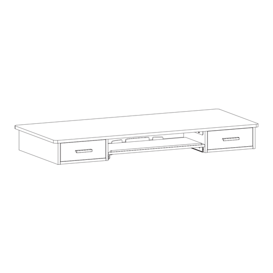
Vintage Brown 55" x 24" Table Top
with Storage Drawers
Instruction Manual
SKU: DESK-TOP5M-N
Scan the QR code with your mobile device or follow the link
for helpful videos and specifications related to this product.
https://vivo-us.com/products/desk-top5m-n
GET IN TOUCH | Monday-Friday from 7:00am-7:00pm CST
help@vivo-us.com
www.vivo-us.com
Chat live with an agent!
309-278-5303
Advertisement

Related Manuals for Vivo DESK-TOP5M-N


Summary of Contents for Vivo DESK-TOP5M-N
- Page 1 Vintage Brown 55” x 24” Table Top with Storage Drawers Instruction Manual SKU: DESK-TOP5M-N Scan the QR code with your mobile device or follow the link for helpful videos and specifications related to this product. https://vivo-us.com/products/desk-top5m-n GET IN TOUCH | Monday-Friday from 7:00am-7:00pm CST help@vivo-us.com...
-
Page 2: Package Contents
WARNING! If you do not understand these directions, or if you have any doubts about the safety of the installation, please call a qualified technician. Check carefully to make sure there are no missing or defective parts. Improper installation may cause damage or serious injury. Do not use this product for any purpose that is not explicitly specified in this manual and do not exceed weight capacity. -
Page 3: Assembly Steps
ASSEMBLY STEPS STEP 1 Insert two Cam Lock Screws (S-D) each into the back of both Outer Drawer Frame (C) pieces, using the top and bottom holes. Slide Outer Drawer Frame (C) pieces into sides of Drawer Frame Back (B) with Connecting Dowels (S-F) in middle holes. Please Note: Rails should be towards the front, as shown below, with three larger holes on the bottom. - Page 4 STEP 2 Insert nine Cam Lock Screws (S-D) into the underside of Main Desktop (A) in pre-drilled holes shown below using a Phillip screwdriver, then place six Connecting Dowels (S-F) into remaining holes. Slide outer frame assembly onto Main Desktop (A). Screw &...
- Page 5 STEP 3 Loosen the sync rod and crossbar on your desk frame and align the mounting points with the pilot holes on the Main Desktop (A) and Outer Frame. Then connect the desk frame to the Main Desktop using the M5x16mm screws included with your desk frame and a Phillips screwdriver. Tighten the sync rod and crossbar to secure the desk frame.
- Page 6 STEP 4 Install two Cam Lock Screws (S-D) into both Outer Drawer Frame (C) pieces using a Phillips screwdriver. Then use Connecting Dowels (S-F) on each side to slide Drawer Frame Bottom (E) pieces into the Outer Drawer Frame. Please Note: One Drawer Frame Bottom (E1) piece has pilot holes pre-drilled for your desk frame’s controller.
- Page 7 STEP 5 There is a slider rail on both sides of Inner Drawer Frame (D), one at the bottom, and one in the middle on the other side. Attach Mounting Brackets (K) to Side 1 of Inner Drawer Frame (D) pieces using ST5x15mm Screws (S-B) and a Phillips screwdriver.
- Page 8 STEP 6 Secure Mounting Brackets (K) to Main Tabletop (A) using ST5x15mm Screws (S-B) and a Phillips screwdriver. Flip desk over then install Cam Locks (S-E) into Drawer Frame Bottoms, ensuring arrows are facing the back of the desk before tightening with 5mm Allen Wrench (T-A).
- Page 9 STEP 7 Install one Cam Lock Screw (S-D) into Drawer Sides (F) using a Phillips screwdriver, then slide into Drawer Back (G) with Connecting Dowels (S-F). Ensure Slider Rails are on the outside. Insert Cam Locks (S-E) into Drawer Back (G) ensuring that the arrows are pointing outward towards Drawer Sides and tighten with the Phillips end of 5mm Allen Wrench (T-A).
- Page 10 STEP 8 Install Drawer Handle (O) on Drawer Front (H) using S4×20mm Screws (S-A) using Phillips screwdriver. Install two Cam Lock Screws (S-D) into Drawer Front (H) using a Phillips screwdriver, then slide into Drawer Sides (F) with Connecting Dowels (S-F).
- Page 11 STEP 9 Insert Cam Locks (S-E) into Drawer Sides (F) ensuring that the arrows are pointing toward Drawer Front and tighten with the Phillips end of 5mm Allen Wrench (T-A). Cam Lock arrows should be facing Drawer Front Slide both drawers into the desk.
- Page 12 STEP 10 Attach Keyboard Tray Bracket (L) into Keyboard Tray (J) using ST5x15mm Screws (S-B), DO NOT FULLY TIGHTEN until keyboard tray is installed on desk. Ensure that Slider Rails are on facing outward. Attach Keyboard Stop (M) using ST5x10mm Screws (S-C). Remove adhesive backing and place Attach Wrist Pad (N) on the front edge of the Keyboard Tray (J).
- Page 13 STEP 11 Slide keyboard tray onto slider rails on desk. Tighten and secure ST5x15mm Screws (S-B) on the underside of the keyboard tray.
- Page 14 STEP 12 Install your desk controller on the bottom of either drawer using M5x16mm screws provided with desk frame using a Phillips screwdriver. NOTE: THESE PARTS ARE NOT INCLUDED IN THIS PACKAGE.
- Page 15 STEP 13 Connect motor cable and power cable to controller securing to bottom of drawer using cable clips. Ensure there is enough slack in cables going to the control panel so that the drawer can still be used without damaging the controller. NOTE: THESE PARTS ARE NOT INCLUDED IN THIS PACKAGE.
- Page 16 : 1HR 8M (within office hrs) - 23% within < 15m - 38% within < 30m - 61% within < 1hr - 83% within < 2hr - 92% within < 3hr FOR MORE VIVO PRODUCTS, CHECK OUT OUR WEBSITE AT: www.vivo-us.com...
Need help?
Do you have a question about the DESK-TOP5M-N and is the answer not in the manual?
Questions and answers