
Related Manuals for Vivo DESK-TOP55B-H


Summary of Contents for Vivo DESK-TOP55B-H
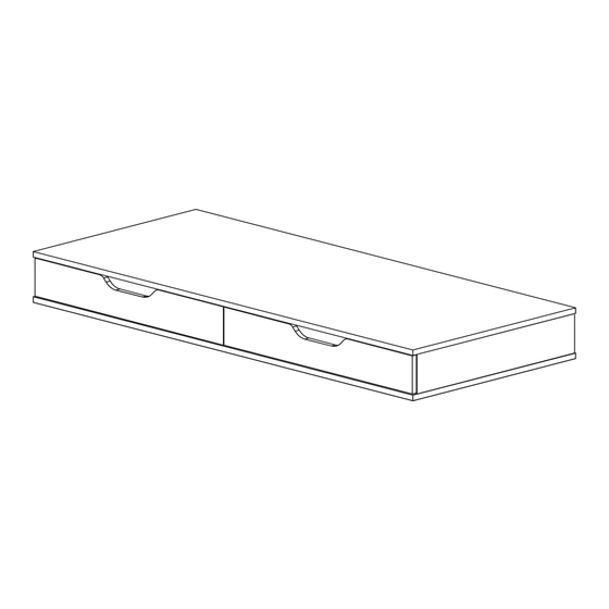
- Page 1 55” x 24” Table Top with Drawers & Built-in Power Strip SKU: DESK-TOP55B-H Instruction Manual Assembly Video & Product Info www.vivo-us.com/products/desk-top55b-h...
-
Page 2: We're Here For You
If you do not understand these directions, or if you have any doubts about the safety of the installation, please contact our product support team at 309-278-5303 or help@vivo-us.com for further assistance. Check carefully to make sure there are no missing or defective parts. Improper installation may cause damage or serious injury. Do not use this product for any purpose that is not explicitly specified in this manual. -
Page 3: Package Contents
Package Contents Desktop Assembly A (x1) B (x1) C (x1) Upper Desktop Lower Desktop Middle Support D (x1) E (x1) F (x1) Side Support Side Support Back Support (Left) (Right) Drawer Assembly I (x2) G (x2) H (x2) Drawer Back Right Wall Left Wall J (x1) -
Page 4: Included Hardware & Tools
Misc. Parts O (x1) N (x1) Grommet Cover Power Strip Included Hardware & Tools S-A (x22) S-B (x25) S-C (x25) S-D (x3) ST4x35mm Screws Cam Lock Nut Cam Lock Screw ST4x12mm Screw S-E (x21) S-F (x16) Wooden Dowel ST5x15mm Screw Tools Needed: Weight Capacity: 154lbs... -
Page 5: Assembly Steps
ASSEMBLY STEPS STEP 1 Screw Cam Lock Screws (S-C) into Left and Right Drawer Front Panels (J, K) using a Phillips screwdriver or Drill. Slide Drawer Left and Right Walls (G,H) over the Cam Lock Screws on Left and Right Drawer Front Panels. S-D (x8) Ensure Channels are at the bottom when installing... - Page 6 STEP 2 Insert Cam Lock Nuts (S-B) into the Left and Right Walls (G,H) with the arrow on Nut and opening facing the Cam Lock Screws (S-C). Use a Phillips screw driver to turn the Cam Lock Nuts clockwise, one half turn. S-B (x8) Slide the Drawer Bottoms (L) into the channels on the Drawer Panels, as shown below.
- Page 7 STEP 3 Attach the Drawer Back (I) onto the Left and Right Wall (G,H ) using ST4x35mm Screws (S-A) and a Phillips screwdriver or drill. Ensure the Drawer Bottoms (L) fit snug into the channels on Drawer Backs. S-A (x8) Place Drawer Mats (M) into the drawer assemblies.
- Page 8 STEP 4 Install Cam Lock Screws (S-C ) into the Left and Right Side Suports (D,E) using a Phillips screwdriver or drill. Press Wooden Dowels (S-E) into the Supports and slide into the Back Back (F). S-C (x4) S-E (x2)
- Page 9 STEP 5 Install Cam Lock Screws (S-C) and Wooden Dowerls (S-E) into the Upper Desktop (A) using a Phillips screwdriver or Drill for Cam Lock Screw, following the placement shown below. Place the Support Assembly over the Cam Lock Screws and Wooden Dowels onto Upper Desktop and press into place.
- Page 10 STEP 6 Insert the Cam Lock Nuts (S-B) into the holes on Support Assembly with the arrow and opening facing towards the previously installed Cam Lock Screws. Use a Phillips screw driver to turn the Cam Lock Nuts clockwise, one half turn. S-B (x12)
- Page 11 STEP 7 Install Cam Lock Screws (S-C) and Wooden Dowels (S-E) into Upper Desktop (A), using a Phillips screwdriver or Drill for the Cam Lock Screws. Slide Middle Support (C) over the Cam Lock Screws and Wooden Dowel Pins and press to secure. S-C (x3) S-E (x2)
- Page 12 STEP 8 Insert the Cam Lock Nuts (S-C) into the Middle Panel (C) with the arrow and opening facing towards the Cam Lock Screws. Use a Phillips screw driver to turn the Cam Lock Nuts clockwise, one half turn. S-B (x3) STEP 9 Install the Power Strip (N) onto the outside of Back Support (F) using ST4x12mm Screws (S-D) tightening with a Phillips screwdriver or Drill.
- Page 13 STEP 10 Press Wooden Dowel (S-E) into Support Assembly as shown. Press the Grommet Cover (O) into the Lower Desktop (B), with Pilot Holes facing up. Place the Lower Desktop over the Wooden Dowel onto the assembly. S-E (x8) Secure Lower Desktop (B) to the desktop assembly using ST4x35mm Screws (S-A) tightening with a Phillips screwdriver or drill.
- Page 14 STEP 11 Feed the cable from Power Strip (N) down and out through the Grommet Cover (O). STEP 12 Slide the Drawer assemblies onto inside rails of desktop assembly. ** LEAVE STICKERS ON PARTS *** For ease of placing drawers on the correct sides, leave stickers on the front panels until the drawer are installed.
- Page 15 Connecting to a Desk Frame If you are using a VIVO frame, some pilot holes have been provided. Install the desktop assembly onto your desk frame using ST5x15mm Screws (S-F) tightening with a Philliups screwdriver or Drill Predrilling Instructions (if needed):...
-
Page 16: Last Updated
LAST UPDATED: 01/02/24 REV1 v1.0 Need Help? Get In Touch Monday-Friday from 7:00am-7:00pm CST help@vivo-us.com www.vivo-us.com 309-278-5303 Chat live with an agent! FOR MORE GREAT VIVO PRODUCTS, CHECK OUT OUR WEBSITE AT: WWW.VIVO-US.COM VIVO-us @vivo_us...
Need help?
Do you have a question about the DESK-TOP55B-H and is the answer not in the manual?
Questions and answers