Table of Contents
Advertisement
Quick Links
Installation, Operation and Maintenance Manual
MAN 601 Rev. 8
April 2024
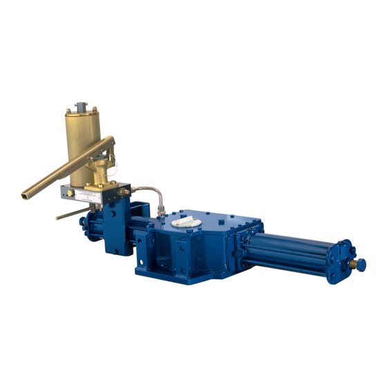
Biffi GIG
Double-Acting Direct Gas Actuator
Copyright © Biffi. The information in this document is subject to change without notice. Updated installation, operation and maintenance manual can be obtained from our website
www.biffi.it or from your nearest Biffi Center: Biffi Italia s.r.l. - Strada Biffi 165, 29017 Fiorenzuola d' A rda (PC) – Italy PH: +39 0523 944 411 – biffi_italia@biffi.it
Advertisement
Table of Contents

Related Manuals for BIFFI GIG


Summary of Contents for BIFFI GIG
- Page 1 Copyright © Biffi. The information in this document is subject to change without notice. Updated installation, operation and maintenance manual can be obtained from our website www.biffi.it or from your nearest Biffi Center: Biffi Italia s.r.l. - Strada Biffi 165, 29017 Fiorenzuola d’ A rda (PC) – Italy PH: +39 0523 944 411 – biffi_italia@biffi.it...
- Page 2 Notes Installation, Operation and Maintenance Manual April 2024 MAN 601 Rev. 8 This page is intentionally left blank.
-
Page 3: Table Of Contents
Installation, Operation and Maintenance Manual Table of Contents MAN 601 Rev. 8 April 2024 Table of Contents Section 1: General Warnings Generalities ......................1 1.1.1 Applicable Regulation ................1 1.1.2 Terms and Conditions ................2 Identification Plate ....................2 Introducing the Actuator ..................3 Data Sheet ........................3 Section 2: Installation Checks upon Actuator Receipt ................4 Actuator Handling ....................4... - Page 4 Table of Contents Installation, Operation and Maintenance Manual MAN 601 Rev. 8 April 2024 Section 6: Troubleshooting Failure or Breakdown Research ................ 45 Section 7: Layouts Spare Parts Order ....................46 Parts List for Maintenance and Replacement Procedure ......47 Section 8: Date Report for Maintenance Operations Date Report for Maintenance Operations ..............
-
Page 5: Section 1: General Warnings
Biffi Italia s.r.l. pays the highest attention to collecting and verifying the documentation contained in this Installation, Operation and Maintenance manual. However Biffi Italia s.r.l. is not liable for any mistakes contained in this manual, for damage or accidents due to the use of the latter. The information contained is of exclusive reserved ownership of Biffi Italia s.r.l. -
Page 6: Terms And Conditions
MAN 601 Rev. 8 1.1.2 Terms and Conditions Biffi Italia s.r.l. guarantees that all the items produced are free of defects in workmanship and manufacturing materials and meet relevant current specifications, provided they are installed, used and serviced according to the instructions contained in the present manual. -
Page 7: Introducing The Actuator
The actuator yoke has a hole with keyways suitable for the assembly of an insert bush the internal hole of which is machined (by Biffi or at customer’s care), according to the shape and dimensions of the valve stem. Biffi can supply different types of control system following customer’s requirements. -
Page 8: Section 2: Installation
Section 2: Installation Installation, Operation and Maintenance Manual April 2024 MAN 601 Rev. 8 Section 2: Installation Checks Upon Actuator Receipt • Check that the model, the serial number of the actuator and the technical data reported on the identification plate correspond with those of order confirmation, see Section 1.2. - Page 9 Installation, Operation and Maintenance Manual Section 2: Installation MAN 601 Rev. 8 April 2024 Figure 4. Lifting Points for GIG/GIG-MHP/GIG-MSJ/GIG-MHW Actuators 1-2 = LIFTING POINTS (OBLIGATORY) 3 = BALANCING POINT 1 = POINT OF SUPPORT 2 = SUPPORTS FOR LATERAL POSITIONING...
-
Page 10: Storage
AND ACTUATOR TOGETHER. DO NOT DISASSEMBLE TOP OR BOTTOM COVER. SPRING LOADED. POTENTIAL ELECTROSTATIC CHARGE HAZARD Biffi IS NOT LIABLE FOR ANY PERSONNEL INJURY DUE TO INCORRECT USE. REFER TO IOM Storage If the actuator needs storage before installation, follow these steps: •... -
Page 11: Actuator Assembly On The Valve
The yoke is bored with keyways for coupling to the valve stem, the dimensions of which are according to Biffi standard tables SCN6200 and SCN6201 (see Tables 1 to 4 for more details). Installation... - Page 12 Section 2: Installation Installation, Operation and Maintenance Manual April 2024 MAN 601 Rev. 8 Figure 6. Coupling Dimensions - Models 0.3 to 6 DRIVE SLEEVE Ød +0.1 Ød Ød ±0.2 Ød N. THREADED HOLES PCD, NUMBER AND SIZE ACCORDING TO ISO 5211 (BUT THE HOLES ARE ON CENTERLINE INSTEAD OF STRADDLE THE CENTERLINE)
- Page 13 Installation, Operation and Maintenance Manual Section 2: Installation MAN 601 Rev. 8 April 2024 Figure 7. Coupling Dimensions - Models 14 to 42 DRIVE SLEEVE Ød Ø d +0.1 Ød ±0.2 Ød N. THREADED HOLES PCD, NUMBER AND SIZE ACCORDING TO ISO 5211 W D10 FLOW LINE Ød...
- Page 14 Section 2: Installation Installation, Operation and Maintenance Manual April 2024 MAN 601 Rev. 8 Figure 8. Coupling Dimensions - Models 50 and 60 DRIVE SLEEVE Ød +0.1 Ø d Ød ±0.2 Ød N. THREADED HOLES FLANGE SIZING ACCORDING TO ISO 5211 W D10 FLOW LINE Ø...
- Page 15 MAN 601 Rev. 8 April 2024 If required, for the standard models size 0.3 to 6, Biffi can supply an insert bush with an unmachined bore in accordance with Biffi standard table SCN6202 enclosed (see following pages). On request, the insert bush bore can be machined by Biffi to couple the valve stem.
-
Page 16: Assembly Procedure
Section 2: Installation Installation, Operation and Maintenance Manual April 2024 MAN 601 Rev. 8 2.4.2 Assembly Procedure NOTICE Failure to comply with the following procedures may impair product warranty. WARNING Installation, commissioning and maintenance, and repair works should be carried out by qualified staff. A non-conforming assembly could be the source of serious accidents. -
Page 17: Pneumatic Connections
Check the pneumatic connections for leakage. NOTICE If it is necessary to mount components not in Biffi's scope of supply, please check the accessory's mounting hole details in the documents TN 1028 (for metric dimension) or TN 1028U (for imperial dimension). -
Page 18: Electrical Connections (If Any)
Section 2: Installation Installation, Operation and Maintenance Manual April 2024 MAN 601 Rev. 8 Electrical Connections (If Any) WARNING Use components appropriate per type, material and dimensions. The connections should be made by qualified staff. Before carrying out any operation, cut line power off. -
Page 19: Commissioning
Installation, Operation and Maintenance Manual Section 2: Installation MAN 601 Rev. 8 April 2024 Commissioning WARNING Check to see if the values of electrical supply to the control group (if foreseen) are compatible with those on the plate on the junction box (Figure 10). Installation, commissioning and maintenance and repair works should be made by qualified staff. -
Page 20: Section 3: Operation And Use
(see Section 3.5) is adjustable by bidirectional flow regulators (item 276) for GIG and GIG with manual jackscrew or handwheel (see Figure 12); for models with manual hand pump, speed is adjusted by unidirectional flow regulators (item Fa –... -
Page 21: Typical Control Schematics
Installation, Operation and Maintenance Manual Section 3: Operation and Use MAN 601 Rev. 8 April 2024 3.1.1 Typical Control Schematics Figure 12. Direct Gas Actuator Local and Remote Control With “MSJ” (GIG-1) OPEN CLOSE E.M. PNEUMATIC SUPPLY TO OPEN OPTIONAL GAS EXHAUST T.E. - Page 22 Section 3: Operation and Use Installation, Operation and Maintenance Manual April 2024 MAN 601 Rev. 8 Figure 13. Direct Gas Actuator Local and Remote Control With “MHP” (GIG-2) OPEN CLOSE E.M. T.E. EXHAUST AUXILIARY GAS SUPPLY ELECTRIC CONNECTION CONNECTION TO SOLENOID VALVES...
- Page 23 Installation, Operation and Maintenance Manual Section 3: Operation and Use MAN 601 Rev. 8 April 2024 Figure 14. Direct Gas Actuator Local and Remote Control - Twin Gas Cylinder (GIG-3) OPEN CLOSE E.M. T.E. ELECTRIC EXHAUST CONNECTIONS GAS SUPPLY CONNECTION...
-
Page 24: Residual Risks
Section 3: Operation and Use Installation, Operation and Maintenance Manual April 2024 MAN 601 Rev. 8 Residual Risks WARNING It is recommended to pipe the exhaust gas. The actuator has parts under pressure. Exercise due caution. Use individual protections provided for by the laws and provisions in force. Operations 3.3.1 Local Pneumatic Operation... -
Page 25: Electric Remote Control To Open And To Close
See Figure 12 when sufficient line pressure is not available. Figure 16. The MSJ (jackscrew manual override with removable lever) or the MHW (jackscrew manual override with handwheel), can be supplied for GIG actuators up to model 3. Operation and Use... - Page 26 Section 3: Operation and Use Installation, Operation and Maintenance Manual April 2024 MAN 601 Rev. 8 • Engage the manual override by rotating its handle. • Turn the lever (or the handwheel) the manual override clockwise to close, or counterclockwise to open •...
-
Page 27: Emergency Manual Operation By Mhp
Installation, Operation and Maintenance Manual Section 3: Operation and Use MAN 601 Rev. 8 April 2024 3.3.4 Emergency Manual Operation by MHP See Figures 13 and 14 – when sufficient line pressure is not available. Figure 18. Figure 19. • Select by the lever 5-D the manual opening or manual closing operation. - Page 28 Section 3: Operation and Use Installation, Operation and Maintenance Manual April 2024 MAN 601 Rev. 8 WARNING If no other manual operation is carried out, the lever 5-D must be in “remote operation” position to allow the operations with gas supply. To ensure that the manual override has been correctly disengaged after a manual override operation, the following actions must be done: •...
- Page 29 Installation, Operation and Maintenance Manual Section 3: Operation and Use MAN 601 Rev. 8 April 2024 Figure 21. MHP With Lockable Hand Pump and Signalling Switch (Please see also Section 7.2, Figure 41). NOTICE Assemble the MHP in vertical position (as shown in Figure 22) so the actuator will work properly.
-
Page 30: Calibration Of The Angular Stroke
Section 3: Operation and Use Installation, Operation and Maintenance Manual April 2024 MAN 601 Rev. 8 Calibration of the Angular Stroke The angular stroke of the yoke can be adjusted between 82° to 98° (±4° with respect to the nominal positions of complete opening and closing) by means the mechanical stops screwed into the left side of the housing (open valve) and into the end flange of the hydraulic cylinder (closing) (Figure 23). - Page 31 Installation, Operation and Maintenance Manual Section 3: Operation and Use MAN 601 Rev. 8 April 2024 For the adjustment of the mechanical stop on the end flange of cylinder, follow these steps (Figure 25): • Remove with the specific wrench (C1) the plug (T). •...
- Page 32 Turn counterclockwise to increase the angular stroke, turn clockwise to decrease it. • When the adjustment is over, tighten the locknut (D). Figure 26. Mechanical Stop on the Housing Table 12. GIG Actuator Model Wrench C1 (mm) Wrench C2 (mm) Operation and Use...
- Page 33 MAN 601 Rev. 8 April 2024 Figure 27. Mechanical Stop on the Housing Table 13. GIG Actuator Model Wrench C1 (mm) Wrench C2 (mm) Figure 28. (Optional - If Foreseen) For the adjustment of the mechanical stop screwed on the end flange of the manual override (see Section 7.2, Figure 43).
- Page 34 April 2024 MAN 601 Rev. 8 Figure 29. Mechanical Stop on the End Flange of Manual Override Table 14. GIG Actuator Size Wrench C1 (mm) Wrench C2 (mm) Figure 30. Mechanical Stop on the End Flange of Manual Override Table 15.
-
Page 35: Calibration Of Microswitches (If Foreseen)
Installation, Operation and Maintenance Manual Section 3: Operation and Use MAN 601 Rev. 8 April 2024 Calibration of Microswitches (If Foreseen) Refer to Safety Instructions Manual for limit switch box. WARNING Refer only to technical documentation related to installed switch box model. NOTICE For mounting interface dimension of the limit switch box on the cover of the actuator, please refer to TN1163V (for metric dimension) or TN1163VU... -
Page 36: Calibration Of The Operation Time
MAN 601 Rev. 8 Calibration of the Operation Time The calibration of the operation time is made by Biffi Italia s.r.l, according to customer requirements and to technical data sheet included in technical documentation. If necessary, it is possible to modify or reset the operating time through two-flow regulation valves placed between the control valves enclosure and the pneumatic cylinder (Figure 31). - Page 37 Section 3: Operation and Use MAN 601 Rev. 8 April 2024 For GIG actuator models with a manual hand pump, the operating time is adjustable through two regulation valves placed on manual hand pump body (see Section 7.2, Figure 41).
-
Page 38: Section 4: Operational Tests And Inspections
Section 4: Operational Tests and Inspections Installation, Operation and Maintenance Manual April 2024 MAN 601 Rev. 8 Section 4: Operational Tests and Inspections NOTICE To ensure the guaranteed SIL grade, according to IEC 61508, the functionality of the actuator must be checked at regular intervals, as described in the Safety Manual. -
Page 39: Section 5: Maintenance
Installation, commissioning and maintenance and repair works should be carried out by qualified staff. Periodic Maintenance GIG actuators are designed to operate long-term in heavy-duty operating conditions, without maintenance needs. NOTICE Periodicity and regularity of inspections is particularly influenced by specific environmental and working conditions. -
Page 40: Check And Restore Oil Level In The Hydraulic Manual Override
Installation, Operation and Maintenance Manual Section 5: Maintenance April 2024 MAN 601 Rev. 8 Figure 33. Level Measuring Stick Maximum level Minimum level 5.1.1 Check and Restore Oil Level in the Hydraulic Manual Override Operate the distributor lever to “closing manual operation”. Figure 34. - Page 41 April 2024 NOTICE For refill use oil of the same brand as previous, refer to related technical documentation. Table 16. Hydraulic Oil List by Biffi Italia s.r.l. for Refilling in Different Working Conditions Standard Temperature Conditions (-30 to +85 °C): Producer...
- Page 42 Installation, Operation and Maintenance Manual Section 5: Maintenance April 2024 MAN 601 Rev. 8 Gas supply dehydrating filter maintenance (if foreseen) The gas supply filter is fitted with a mechanical filter and a drain valve to discharge periodically the water generated by the condensation of the humidity inside the gas supply.
-
Page 43: Extraordinary Maintenance
Installation, Operation and Maintenance Manual Section 5: Maintenance MAN 601 Rev. 8 April 2024 Extraordinary Maintenance If there are leaks in the hydraulic cylinder, or a malfunction in the mechanical components, or in case of scheduled preventive maintenance, the actuator must be disassembled and seals must be replaced with reference to the following general sectional drawing and adopting the following procedures. - Page 44 Installation, Operation and Maintenance Manual Section 5: Maintenance April 2024 MAN 601 Rev. 8 5.2.1.1 Seals Replacement Prior to reassemble, check if the actuator components are in good condition and clean. Lubricate all the surfaces of the parts, which move in contact with other components, by recommended grease (Molykote 2003 Lubcon Turmoplex LTA 2 ®...
- Page 45 Installation, Operation and Maintenance Manual Section 5: Maintenance MAN 601 Rev. 8 April 2024 5.2.1.2 Reassemble Assemble the new gasket (37 and 39) after cleaning the surfaces of housing (8), the flange (38) and head flange (42), which are in contact. Assemble the head flange (42), replace the washers if damaged, tighten the screws (31) to the recommended torque.
- Page 46 Installation, Operation and Maintenance Manual Section 5: Maintenance April 2024 MAN 601 Rev. 8 Figure 36. GIG-MHP Double-Acting Pneumatic Actuator Table 17. Parts List Item Description Item Description Cover Spring washer Screw Guide block pin Plug Vent valve Sliding block...
-
Page 47: Dismantling And Demolition
Installation, Operation and Maintenance Manual Section 5: Maintenance MAN 601 Rev. 8 April 2024 Dismantling and Demolition Before starting the disassembly, a large area should be created around the actuator to allow any kind of movement without problems of further risks created by worksite. WARNING Before disassembling the actuator, it is necessary to close the pneumatic feed line and discharge oil pressure from the cylinder of the actuator, from the control unit and... -
Page 48: Lubrication Of Mechanism
If the service is not special (i.e., Oxygen, Hydrogen or other mentioned during the offer stage). Use an equivalent or better product in compliance with the grease proposed in the actual scope of supply by Biffi Fiorenzuola. Your grease supplier can verify and propose an alternative product at your responsibility. Maintenance... -
Page 49: Section 6: Troubleshooting
Wrong position of the distributor of the Restore correct position Actuator does not work manual hydraulic group Failure of the control group Call Biffi Italia s.r.l. Customer Service Unexpected intervention of torque Call Biffi Italia s.r.l. Customer Service limit-device Low supply pressure Restore (Section 1.4) -
Page 50: Section 7: Layouts
Section 7: Layouts Spare Parts Order For spare parts order to the relevant Biffi office, please make reference to Biffi order confirmation concerning all the supply, and serial number of the actuator (Section 1.2) for any specific spare part for a specific actuator model. -
Page 51: Parts List For Maintenance And Replacement Procedure
Installation, Operation and Maintenance Manual Section 7: Layouts MAN 601 Rev. 8 April 2024 Parts List for Maintenance and Replacement Procedure Figure 37. Scotch Yoke Mechanism Table 19. Parts List Item Quantity Description Material O-ring * NBR Yoke bushing Bronze Retainer ring Stainless steel Housing... - Page 52 Section 7: Layouts Installation, Operation and Maintenance Manual April 2024 MAN 601 Rev. 8 Figure 38. Pneumatic Cylinder Table 20. Parts List Item Quantity Description Material Piston rod bushing Steel + Bronze + PTFE Head flange Carbon steel O-ring * NBR rubber Piston rod seal ring * PTFE + Graphite O-ring...
- Page 53 Installation, Operation and Maintenance Manual Section 7: Layouts MAN 601 Rev. 8 April 2024 Figure 39. Hydraulic Cylinder for MHP Table 21. Parts List Item Quantity Description Material Piston rod bushing Steel + Bronze + PTFE Head flange Carbon steel O-ring * NBR rubber Piston rod seal ring...
- Page 54 Section 7: Layouts Installation, Operation and Maintenance Manual April 2024 MAN 601 Rev. 8 Figure 40. Assembly Kit Table 22. Parts List Item Quantity Description Material Screw Alloy steel Carbon steel Carbon steel Screw Alloy steel Flange Carbon steel Gasket * Fiber Stopper bush Alloy steel...
- Page 55 Installation, Operation and Maintenance Manual Section 7: Layouts MAN 601 Rev. 8 April 2024 Figure 41. Hydraulic Control Unit MHP Layouts...
- Page 56 Section 7: Layouts Installation, Operation and Maintenance Manual April 2024 MAN 601 Rev. 8 Table 23. Parts List Item Quantity Description Material Dipstick Cap nut Carbon steel Washer Carbon steel + Rubber Hydraulic tank Carbon steel Hand pump See attached table O-ring * Fluorosilicon rubber Ball...
- Page 57 Installation, Operation and Maintenance Manual Section 7: Layouts MAN 601 Rev. 8 April 2024 Figure 42. Hand Pump Table 24. Parts List Item Quantity Description Material Ball Stainless steel Delivery valve bush Carbon steel Suction valve bush Carbon steel Spring Stainless steel Suction valve ring Carbon steel...
- Page 58 Section 7: Layouts Installation, Operation and Maintenance Manual April 2024 MAN 601 Rev. 8 Figure 43. Jackscrew Manual Override MSJ or MHW Table 25. Parts List Item Quantity Description Material Protection pipe Carbon steel Jackscrew Carbon steel Engagement lever pin Stainless steel O-ring * Fluorosilicon rubber...
-
Page 59: Date Report For Maintenance Operations
Installation, Operation and Maintenance Manual Section 8: Maintenance Operations MAN 601 Rev. 8 April 2024 Section 8: Date Report for Maintenance Operations Last maintenance operation date: (in factory, on delivery): ……… exec. by: ………… ……… exec. by: ………… ……… exec. by: ………… Next maintenance operation date: ………... - Page 60 VCIOM-03401-EN © 2024 Biffi. All rights reserved. Biffi Italia s.r.l. Strada Biffi 165 The contents of this publication are presented for informational purposes 29017 Fiorenzuola d’Arda (PC) only, and while every effort has been made to ensure their accuracy, Italy...
Need help?
Do you have a question about the GIG and is the answer not in the manual?
Questions and answers