
Related Manuals for Landoll Brillion PFT20-22


Summary of Contents for Landoll Brillion PFT20-22
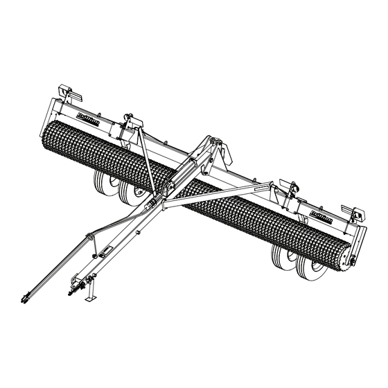
- Page 1 ‘ Floating Ring Pulverizer Models PFT20-22 Operator’s Manual LANDOLL COMPANY, LLC 1900 North Street Marysville, Kansas 66508 (785) 562-5381 800-428-5655 ~ WWW.LANDOLL.COM F-780-2407...
- Page 2 Manuals for Floating Ring Pulverizer PFT20-22 Manual Number Manual Type F-780 Operator’s Manual F-779 Parts Manual...
- Page 3 DANGER DO NOT operate or perform any maintenance tasks on this equipment until you have completed the following: 1. Receive proper training to operate this equipment safely. 2. Read and understand the operator’s manual. 3. Be thoroughly trained on inspection and repair procedures. Failure to comply with this warning may result in serious injury or possibly death.
- Page 5 Table of Contents Safety Introduction ............1-1 Description of Unit .
- Page 6 TABLE OF CONTENTS Operation Tractor Preparation..........3-1 Pulverizer Preparation .
-
Page 7: Warranty Registration
Failure to comply with this warning can result in within 10 days of retail purchase, using the Landoll personal injury or death, damage to the Corporation Ag Products on-line registration process. -
Page 8: Transporting Safety
TABLE OF CONTENTS SAFETY Safety • When applying decals to the implement, be sure to clean the surface to remove any dirt or residue. Where possible, sign placement should protect the NOTE sign from abrasion, damage, or obstruction from Investigation has shown that nearly 1/3 of all farm mud, dirt, oil etc. -
Page 9: Maintenance Safety
TABLE OF CONTENTS SAFETY Safety Instructions for Towing Maintenance Safety Vehicles • Block the machine so it will not roll when working on or under it. The maximum travel speed is the lesser of • Transport Locks installed. • The limit of the road conditions; •... -
Page 10: High Pressure Fluid Safety
TABLE OF CONTENTS SAFETY High Pressure Fluid Safety Safety Chain 1. Use a Safety Chain to help control drawn machinery Escaping fluid under pressure can be nearly invisible and should it separate from the tractor drawbar or have enough force to penetrate the skin causing serious implement. - Page 11 TABLE OF CONTENTS SAFETY Bridge Hitch Frame Safety Chain Figure 1-3: Bridge Hitch Safety Chain F-780-2407...
- Page 12 Lower load or relieve hydraulic ITEM 2 - 8J310 pressure before loosening fittings. ITEM 1 3K706 A LANDOLL PRODUCT ITEM 3 - 170510 ITEM 4 - 528934 ITEM 5 - 528933 ITEM 6 - 528938 MEMBER PULVERIZER...
- Page 13 TABLE OF CONTENTS SAFETY Figure 1-5: Decal Locations F-780-2407...
- Page 14 TABLE OF CONTENTS SAFETY Figure 1-6: Decal Locations - Optional Bridge Hitch F-780-2407...
- Page 15 Chapter 2 TABLE OF CONTENTS Assembly IMPORTANT CAUTION All Harnesses must be firmly attached to machine Do Not work on or under this machine unless frame members or Hydraulic Hoses so they do not securely blocked and supported by a hoist or sag or become torn loose by field debris.
-
Page 16: Drawbar Installation
TABLE OF CONTENTS ASSEMBLY Drawbar Installation Do Not over tighten, 1. Bring the rear of the Drawbar into position between Drawbar must be the Frame Hitch Plates at the center of the Frame. free to pivot Place a 1-1/4 x 1-7/8 x 14 ga Machinery Bushing on each side between the Drawbar and the Frame Hitch Plates. - Page 17 TABLE OF CONTENTS ASSEMBLY Locknut, 1-1/4-7 Slotted Pin, Pin,1 x 10-1/8 5/16 x 2 Flat Washer,1" Klik Pin, 1/4 x 1-1/4 Slotted Pin,5/16 x 2 Transport Lock Bolt,1-1/4-7 x 10-1/2 Mach Bushings Frame Hitch Plates Brace Brace Hyd Cyl, 4 x 20 Bolt,5/8-11 x 8 Cotter Pin,1/4 x 2 Manual Storage...
- Page 18 TABLE OF CONTENTS ASSEMBLY Bridge Hitch Installation 2. Attach the Safety Chain to the Bridge Hitch by sliding two 1" Washers between the slotted end of the Safety Chain. Place a 1" Washers between the Safety Chain Bridge Hitch Coupler Installation and the Bridge Hitch.
- Page 19 TABLE OF CONTENTS ASSEMBLY Bridge Hitch Installation 3. Tighten the Slotted Nut so that the Pulverizer Frame is free to pivot on the Bridge Hitch. Insert 1/4 x 2 1. Bring the rear of the Bridge Hitch into position Cotter Pin. Repeat for the Right Hand side. between the Pulverizer Frame Hitch Plates.
-
Page 20: Wheel Arm Assembly
TABLE OF CONTENTS ASSEMBLY Wheel Arm Assembly 2. Apply anti-seize on Spindles. Insert the Hub and Spindle Assembly into the Wheel Arms. Lock Spindles 1. Attach the Wheel Arms to the Frame. See Figure 2-8. in place with the 3/8-16 x 3 Bolts and Locknuts. The Wheel Arms should be equally spaced from the center of the machine. -
Page 21: Tire Installation
TABLE OF CONTENTS ASSEMBLY Tire Installation WARNING Use a torque wrench to assure proper torque. Insufficient torque can cause stud breakage and damage the wheel pilots. Over torque can over stress the studs and strip the threads. NOTE All tire/wheel assemblies are mounted with the valve stem facing outward from Hub and Spindle. -
Page 22: Hydraulic Installation
TABLE OF CONTENTS ASSEMBLY Hydraulic Installation Hydraulic Assembly IMPORTANT CAUTION Lower the unit to the ground and relieve system Do Not raise the machine without the use of pressure before attempting to repair, adjust, or hydraulics. This would introduce air into the disconnect components. - Page 23 TABLE OF CONTENTS ASSEMBLY 4. Connect 3/8 x 185 Hose Assembly to the Cylinder 7. Secure hoses with Twin Clamps, Top Plate and Rod End Elbow Restrictor and 3/8 x 161 Hose 5/16-18 1-1/4 Bolts in the mounts provided on the Assembly to the Ball Valve Adapter Fitting.
- Page 24 TABLE OF CONTENTS ASSEMBLY Figure 2-12: Hydraulic Hose Installation - Bridge Hitch 2-10 F-780-2407...
-
Page 25: Purging The Hydraulic System
TABLE OF CONTENTS ASSEMBLY Purging the Hydraulic System 6. Recheck tractor reservoir to make sure it is within operating limits. 7. Raise the Pulverizer and install the Transport Lock IMPORTANT Pin (Drawbar) or Transport Lock (Bridge Hitch). Lower the unit to the ground and relieve system See Figures 3-1 and 3-4. - Page 26 TABLE OF CONTENTS ASSEMBLY Warning Lamp Installation Pulverizer with Bridge Hitch When using the Bridge Hitch an additional 33FT 7-Pin AG Pulverizer with Drawbar Harness is required. Route this harness up the Bridge Hitch Frame along the hydraulic hoses. Secure cords 1.
- Page 27 TABLE OF CONTENTS ASSEMBLY AG Harness,33FT (Used with Bridge Hitch Only) AG Harness,20FT Locknut, 5/16-18 Light Shield Tube w/Bracket Bolt,1/4-20 x 1-1/2 Flasher Control Module Bolt, Locknut, 1/4-20 x 2 1/4-20 Lamp Harness Flat Washer,6/16 Flange Bolt, Locknut,1/2-13 5/16-18 x 1 Light Shield Locknut, Tube...
- Page 28 TABLE OF CONTENTS ASSEMBLY Table provided for general use. NOTES: 2-14 F-780-2407...
-
Page 29: Tractor Preparation
Chapter 3 TABLE OF CONTENTS Operation DANGER DANGER CAUTION Never allow anyone a ride on the seeder at any When transporting farm implements on public time. Allowing a person to ride on the machine can roads, it is the responsibility of the operator to inflict serious personal injury or death to that abide by state and local laws concerning wide person. -
Page 30: Operation
TABLE OF CONTENTS OPERATION Attaching Drawbar Cylinder The Floating Ring Pulverizer is designed to be pulled Drawbar behind tractors, seeders, or tillage tools. The long Drawbar allows for easy turns when pulled behind other equipment. Frame CAUTION Do Not stand between equipment when attaching or detaching the Pulverizer Drawbar unless the implements are not moving. - Page 31 TABLE OF CONTENTS OPERATION Detaching Drawbar Parking Pulverizer lowered 1. Raise the Pulverizer fully to extend the Hydraulic Lift Pulverizer can be stored raised or lowered. Cylinder. 2. Remove the Transport Lock Pin and place it in the Parking Pulverizer raised storage position.
- Page 32 TABLE OF CONTENTS OPERATION DRAWBAR JACK POSITION Jack Retracted 18-3/4" Jack Extended 35" Jack Retracted 20" Jack Extended 44" Figure 3-3: 2nd and 3rd Jack Swivel Positions F-780-2407...
- Page 33 TABLE OF CONTENTS OPERATION Attaching Bridge Hitch Detaching Bridge Hitch NOTE CAUTION Position the towing implement and Pulverizer on a level Do Not stand between two pieces of equipment surface. when attaching or detaching. 1. Install towing implement Transport Locks. 2.
-
Page 34: Field Operations
TABLE OF CONTENTS OPERATION Field Operations The Floating Ring Pulverizer Roller Assembly is designed with rings whose inside diameter is greater than the drum which supports them. This allows the roller wheels to follow the irregular contours of the soil surface. See Figure 3-6. -
Page 35: Hydraulic System
TABLE OF CONTENTS OPERATION Hydraulic System General Operation 1. Horsepower requirements is 90 horsepower. Local IMPORTANT dealers can help in making recommendations for your conditions. Lower the unit to the ground and relieve system pressure before attempting to repair, adjust, or 2. - Page 36 TABLE OF CONTENTS OPERATION Transport 6. Before transporting: • Know the height and width of the implement 1. Check and follow all federal, state, and local being towed. Markers, tanks, attachments, etc. requirements before transporting the Pulverizer. can increase the height and width of the 2.
-
Page 37: General Torque Specifications
Chapter 4 TABLE OF CONTENTS Maintenance General Torque Specifications (rev. 4/97) This chart provides tightening torques for general purpose applications when special torques are not specified on process or drawing. Assembly torques apply to plated nuts and capscrews assembled without supplemental lubrication (as received condition). They do not apply if special graphite moly-disulfide or other extreme pressure lubricants are used. -
Page 38: Maintenance
TABLE OF CONTENTS MAINTENANCE Hydraulic Fitting Torque Specifications 37 degree JIC, ORS, & ORB (REV. 10/97 This chart provides tightening torques for general purpose applications when special torques are not specified on process or drawing. Assembly torques apply to plated nuts and capscrews assembled without supplemental lubrication (as received condition). They do not apply if special graphite moly-disulfide or other extreme pressure lubricants are used. -
Page 39: Lubrication Maintenance
TABLE OF CONTENTS MAINTENANCE Tires Lubrication Maintenance Recommended Tire Size: 11L x 15 - 12 Ply Lubricate with quality grease per recommended lubrication frequency intervals indicated or if machine is Tire Inflation Pressure: 52PSI not used for an extended period. See Figure 4-2. When Re-Installing 1/2-20 x 1 Wheel Bolts tighten to Roller Bearings are maintenance free, require no 50 Ft-Lbs. -
Page 40: Hydraulic Maintenance
TABLE OF CONTENTS MAINTENANCE Hydraulic Maintenance Replacing or Adding Roller Wheels IMPORTANT 1. Attach a tractor to the Pulverizer, put the tractor Lower the Pulverizer to the ground, and relieve transmission into PARK or lock the brakes preventing hydraulic pressure before attempting to service any tractor from moving. - Page 41 TABLE OF CONTENTS MAINTENANCE Parked Tractor with Locked Brakes 2" Bearing Drum Contacting Rollers Roller on Blocks Figure 4-3: Replacing or Adding Roller Wheels - Detail Shim Washer 11 Gauge Shim Washer 14 Gauge Locknut,5/8-11 Shim Washer,11 Gauge Flat Top Washer Thick Washer,3/8 Spring Washer,1"...
-
Page 42: Warning Lamps
TABLE OF CONTENTS MAINTENANCE Warning Lamps Storage When connecting the 7-Pin Warning Lamp Connector: 1. The service life of the Pulverizer will be extended by proper off-season storage practices. Prior to storing 1. Make sure the Tractor has a good clean Receptacle, the unit, complete the following procedures: free of dirt and corrosion. - Page 43 Chapter 5 TABLE OF CONTENTS Specifications Product Attributes PFT20B12 PFT22B12 Approximate Weight 6,120 lbs. (2,776 kg) 6,599 lbs. (2,993 kg) Working Width 20 ft. 0 in. (6.1 m) 22 ft. 0 in. (6.7 m) Transport Width 21 ft. 0 in. (6.4 m) 23 ft.
-
Page 44: Specifications
TABLE OF CONTENTS SPECIFICATIONS Table provided for general use. NOTES: F-780-2407... - Page 45 Document Control Revision Log: Date Form # Improvement(s): Description and Comments 01/20215 F-780-R0 New Release 07/2024 F-780-2407 ECN - 50088 Added Decals: QR Code, FEMA, 20MPH Revised Template...
- Page 46 Equipment from Landoll Company, LLC is built to exacting standards ensured by ISO 9001:2015 registration at all Landoll manufacturing facilities. Floating Ring Pulverizer Models PFT20-22 Operator’s Manual Re-Order Part Number F-780 LANDOLL COMPANY, LLC 1900 North Street Marysville, Kansas 66508 (785) 562-5381 800-428-5655 ~ WWW.LANDOLL.COM...
Need help?
Do you have a question about the Brillion PFT20-22 and is the answer not in the manual?
Questions and answers