Table of Contents
Advertisement
Quick Links
Advertisement
Table of Contents

Subscribe to Our Youtube Channel
Related Manuals for Bartscher Q 26


Summary of Contents for Bartscher Q 26
- Page 1 Q 26 - Q 46 104304 - 104306...
- Page 2 Bartscher GmbH Phone: +49 5258 971-0 Franz-Kleine-Str. 28 Fax: +49 5258 971-120 D-33154 Salzkotten Technical Support Hotline: +49 5258 971-197 Germany www.bartscher.com Version: 3.0 Date of preparation: 2024-07-12...
- Page 3 Bes chr eibung...
- Page 5 Quick Start Guide TOUCH Operation status LED indicator status Standby every 30” Storage container full every 10” Production cycle start every 0.5” Ice production ON 5” + OFF Alarm blackout ON 3” + OFF Cleaning cycle ATTENTION! Should subsequent alarms appear, contact the service company.
-
Page 7: Table Of Contents
Original instruction manual Safety ......................2 Explanation of Signal Words ..............2 Safety instructions..................3 Intended Use ................... 5 Unintended Use ..................5 General information ..................6 Liability and Warranty ................6 Copyright Protection ................6 Declaration of Conformity ................ 6 Transport, Packaging and Storage .............. -
Page 8: Safety
Safety Diese Bedi enungsanlei tung besc hrei bt di e Installation, Bedi enung und Wartung des Geräts und gilt als wic htige Inform ationsquelle und N achschl agew erk. Di e Kenntnis aller enthaltenen Sic herheits hinw eis e und H andlungs anw eisungen schafft die Vorauss etz ung für das sichere und s ac hger echte Ar beiten mit dem Gerät. D arüber hi naus müs sen die für den Ei ns atz ber eic h des Geräts geltenden ör tlichen Unfallv erhütungsv orsc hriften und allgem einen Sicherheits bestimmungen eing ehalten wer den. Dies e Bedi enungs anleitung is t Bes tandteil des Produkts und m uss i n unmittelbarer N ähe des Ger äts für das In¬s tall ations-, Bedi enungs-, W artungs- und R einigungspers onal jederzeit z ugänglich auf¬bewahrt w erden. W enn das Ger ät an eine dritte Pers on weiterg egeben wird, muss die Bedi enungsanlei tung mit ausgehändigt wer den. -
Page 9: Safety Instructions
Safety WARNING! The signal word WARNING warns against hazards that may lead to moderate or severe injuries or death if the hazards are not avoided. CAUTION! The signal word CAUTION warns against hazards that may lead to light or moderate injuries if the hazards are not avoided. , di e IMPORTANT! The signal word IMPORTANT indicates possible property damages,... - Page 10 Safety • Always completely unwind the power cord. • Never place the appliance or other objects on the power cord. • Always take hold of the plug to disconnect the appliance from the power supply. • Check the power cord regularly for damage. Do not use the appliance if the power cord is damaged.
-
Page 11: Intended Use
Safety Operating personnel • This appliance is not intended to be used by persons (including children) with limited physical, sensory or mental capabilities, nor by persons with limited experience and/or limited knowledge. • Children should be supervised to ensure that they are not playing with or switching the appliance on. -
Page 12: General Information
General information General information Liability and Warranty All information and instructions in this instruction manual account for legal regulations in force, current level of technical engineering knowledge as well as our expertise and experience, developed over the years. If special models or additional options are ordered, or state-of-the-art technical solutions were implemented, the actual scope of delivery of the appliance may, in some circumstances, differ from descriptions and numerous drawings in this instruction manual. -
Page 13: Transport, Packaging And Storage
Transport, Packaging and Storage Transport, Packaging and Storage Delivery Check Immediately upon reception, check the delivery for completeness and possible shipping damage. In the case of visible transport damage refuse to accept the appliance or accept it conditionally. Mark and note the scope of damage in shipping documents/consignment list of the shipping company and lodge a complaint. -
Page 14: Technical Data
Technical Data Technical Data Technical Specifications Ice-cube maker Q 26 Name: 104304 Art. No.: Material: CNS 18/10 Ice cube design: tapered form (hollow taper) Number of ice cube sizes: Ice cube size (W x D x H), in mm: 32,5 x 29 x 41... - Page 15 Technical Data Ice-cube maker Q 46 Name: 104306 Art. No.: Material: CNS 18/10 Ice cube design: tapered form (hollow taper) Number of ice cube sizes: Ice cube size (W x D x H), in mm: 32,5 x 29 x 41 Ice cube weight, in g: Ice cubes output / work cycle: Max.
-
Page 16: List Of Components Of The Appliance
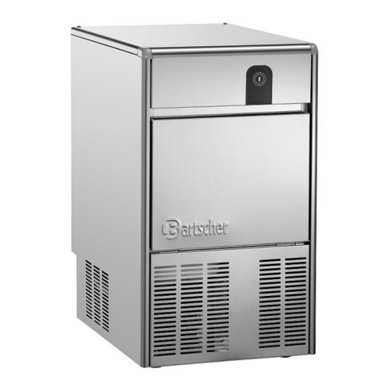
Technical Data List of Components of the Appliance 1. Housing 2. Control key 3. Ice shovel holder 4. Water drain opening 5. Temperature probe 6. Water pan 7. Storage container 8. Storage container door 9. Power cord with mains plug 10. -
Page 17: Operation
Technical Data Operation • The production of ice takes place at the terminations (fingers) of the evaporator, which are plunged in the tank filled with water. Water is constantly stirred by rotating paddles. • Water level may be regulated by rotating the micro-float or water sensor through the designated crevice, located on the right bracket, following screwing the fixing screw 1 off (Fig. -
Page 18: Installation And Operation
Installation and operation Installation and operation Installation CAUTION! Incorrect installation, positioning, operation, maintenance or misuse of the appliance may lead to personal injury or property damage. Positioning and installation, as well as repairs may be performed by authorised technical service only and in compliance with the applicable national law. - Page 19 Installation and operation – sufficiently large, and thus enabling usage of the appliance with no problems; – easily accessible; – well ventilated. • The appliance may be loaded and unloaded with a forklift truck or a pallet truck, with the length of over half of the length of the appliance. •...
- Page 20 Installation and operation • Level the appliance (Fig. 3). If the appliance is not levelled, it may negatively affect its functionality, as well as water supply. Remove Transport Safeguards 1. Remove screws fixing the upper cover. 2. Remove the upper cover. 3.
- Page 21 Installation and operation Power supply connection • Verify if technical data of the appliance (see rating plate) correspond with the local electric power grid specification. • Connect the appliance to a single, properly grounded mains socket with protective contact. Do not connect the appliance to a multi-socket. •...
-
Page 22: Operation
Installation and operation Operation Preparation of Appliance 1. Remove all accessories from the storage container (water supply tube, water drain tube, ice shovel, documentation). 2. Before use, clean the appliance observing instructions in section 6 'Cleaning'. 3. Dry the appliance thoroughly. Indications for User •... - Page 23 Installation and operation Water level may be regulated by rotating the micro-float or water sensor through the designated crevice, located on the right bracket, following screwing the fixing screw 1 off (Fig. 12). This regulation must be performed with power supply disconnected.
- Page 24 Installation and operation Operation Status / Alarm Status Indicators Indicator / Alarm WHITE Too long a cooling cycle alarm blinks 1x ON 3" Pump alarm blinks 1x blinks 1x Change in duration of alarm between blinks 2x ON 3" two production cycles Deposit probe damage alarm blinks 3x ON 3"...
- Page 25 Installation and operation Evaporator high temperature alarm ON 3" blinks 2x Evaporator low temperature alarm ON 3" blinks 4x OFF: LED indicator / colour always off ON: LED indicator / colour always on Blinking: LED indicator / colour on for 0.2 s and off for 0.3 s Malfunctions ATTENTION! In the case of incorrect operation, disconnect the appliance from power...
-
Page 26: Cleaning
Cleaning Cleaning Safety Instructions for Cleaning • Before cleaning, disconnect the appliance from the power supply. • Leave the appliance to cool down completely. • Make sure water does not enter the appliance. Do not immerse the appliance in water or other liquids during cleaning. Do not clean the appliance with a pressurized water jet. - Page 27 Cleaning Descaling and Disinfection To avoid problems caused by water hardness and the formation of contaminants on parts or components in contact with water, the appliance is equipped with "Self Cleaning" function. This function keeps the appliance clean, free of limescale and deposits, thanks to the cleaning action of a special descaling agent.
- Page 28 Cleaning Service Cleaning Air Filter and Condenser In order to maintain performance and extend the life of the appliance, clean the air filter and condenser regularly; the components are located under the front cover of the appliance (Fig. 13): – remove the air filter; –...
-
Page 29: Possible Malfunctions
Possible Malfunctions Possible Malfunctions Mögliche ATTENTION! The table below contains descriptions of possible causes and solutions to malfunctions or errors during operation of the appliance. These malfunctions may be cleared by a qualified refrigeration technician. In such a case, provide article number, model name and serial number. These data may be found in the rating plate. - Page 30 Possible Malfunctions Malfunction Appliance Condition Solution Alarm Condenser high The appliance stops; the Check condenser for cleanliness temperature alarm condenser's fan remains and ventilation on in order to reduce the Check fan for operation condenser's temperature Evaporator probe Appliance stops Check evaporator probe damage alarm connection to PCB...
- Page 31 Possible Malfunctions Malfunction Appliance Condition Solution Alarm Discharge pump Clogged discharge Check the appliance for obstacles alarm opening in discharge route Discharge pump Replace the discharge pump damaged Too long a Defrosting process takes Check filling with coolant defrosting process too long alarm Capacitive sensor...
-
Page 32: Disposal
Disposal Disposal Electrical Appliance Electric appliances are marked with this symbol. Electrical appliances must be disposed of and recycled in a correct and environmentally friendly manner. You must not dispose of electric appliances with household waste. Disconnect the appliance from the power supply and remove power cord from the appliance.
Need help?
Do you have a question about the Q 26 and is the answer not in the manual?
Questions and answers