
Related Manuals for Bartscher F 80C


Summary of Contents for Bartscher F 80C
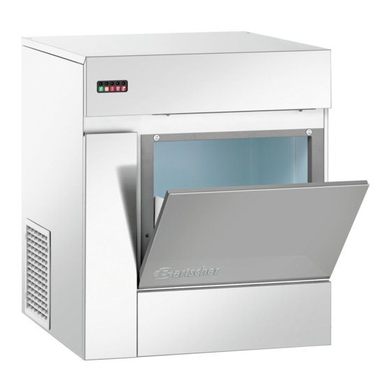
- Page 1 ELECTRONIC MODULAR FLAKERS 1 44 9 F125 1 4436 SERVICE MANUAL 71503135-0-000 service Flakers GB...
-
Page 3: Table Of Contents
TABLE OF CONTENTS Specification F 80C pagina Specification F 125C Specification F 120 Specification F 200 Specification SF 300 Specification SF 500 Specification SFN 1000 GENERAL INFORMATION AND INSTALLATION Introduction Unpacking and Inspection - Ice maker Unpacking and Inspection - Storage bin... - Page 4 TECHNICAL SPECIFICATION ELECTRONIC MODULAR FLAKERS mod. F80 (R 134a) Produzione di ghiaccio in 24 ore fino a kg. 90 Ice produced for 24 hours up to PRODUZIONE DI GHIACCIO Eisproduktion in 24 Stunden bis zu ICE PRODUCTION Production de glace en 24 h jusqu’à EIS PRODUKTION Produccion de hielo en las 24 horas hasta PRODUCTION DE GLACE...
- Page 5 TECHNICAL SPECIFICATION ELECTRONIC MODULAR FLAKERS mod. F125 (R 134a) Produzione di ghiaccio in 24 ore fino a kg. 120 Ice produced for 24 hours up to PRODUZIONE DI GHIACCIO Eisproduktion in 24 Stunden bis zu ICE PRODUCTION Production de glace en 24 h jusqu’à EIS PRODUKTION Produccion de hielo en las 24 horas hasta PRODUCTION DE GLACE...
-
Page 6: General Information And Installation
GENERAL INFORMATION AND INSTALLATION A INTRODUCTION NOTE. To retain the safety and performance the step-by-step procedures for the installation, built into this icemaker, it is important that start- up and operation, maintenance and installation and maintenance be conducted cleaning for the F80 - F125 Modular Icemakers. in the manner outlined in this manual. -
Page 7: Location And Levelling
C. LOCATION AND LEVELLING D. ELECTRICAL CONNECTIONS WARNING. This Modular Flaker See data plate for current requirements to deter- Superflaker is designed for indoor installa- mine wire size to be used for electrical con- tion only. Extended periods of operation at nections. -
Page 8: Water Supply And Drain Connection
E. WATER SUPPLY AND DRAIN WATER SUPPLY - WATER COOLED MODELS CONNECTIONS The water cooled versions of Ice Makers require two separate inletwater supplies, one for the When choosing thewater supply for the ice flaker water making the flaker ice and the other for the consideration should be given to: water cooled condenser. -
Page 9: Installation Pratice
4 Have all the electrical and plumbing con- 9 Have the bin liner and cabinet been wiped nections been made, and is the water supply clean? shut-off valve open? 10 Has the owner/user been given the User 5 Has the voltage been tested and checked Manual and been instructed on the importan- against the data plate rating? ce of periodic maintenance checks? -
Page 10: Operating Instructions
OPERATING INSTRUCTIONS START UP Elapsed the stand by period the unit starts operating with the activation in sequence of the following assemblies: After having correctly installed the ice maker and completed the plumbing and electrical GEAR MOTOR/S connections, perform the following “Start-up” pro- COMPRESSOR cedure. - Page 11 FIG. 2 WATER LEVEL RESET GEAR MOTOR ROTATION CONTACTOR COIL RELAYS CONDENSER TEMP. T 40÷50°C EVAPORATOR TEMP. GEAR MOTOR ICE LEVEL CONTROL TRIAC FAN MOTOR TRANSF. ELECTRONIC CARD FIG. 3 WATER LEVEL RESET GEAR MOTOR ROTATION CONTACTOR COIL RELAYS CONDENSER TEMP. EVAPORATOR TEMP.
- Page 12 NOTE. If, after ten minutes from the NOTE. On air cooled models, the condenser compressor start-up, the evaporating tem- temperature sensor, which is located within perature has not dropped down to a value the condenser fins, keeps the head lower than -1 C (30 F) the evaporating tem- (condensing) pressure between preset...
- Page 13 This will cause a gradual decrease of the water After 3 minutes the unit resumes its total operation level in the float reservoir and as soon as the with the immediate start-up of the gear motor level gets below the two vertical metal pins, the and, few seconds later, of the compressor.
- Page 14 NOTE. The ICE LEVEL CONTROL NOTE. In the front of the PC Board is located (INFRARED SYSTEM) is independent of the a small I/R Trimmer directly connected with temperature however, the reliability of its the optical Ice level control. By means of its detection can be affected by external light screw it is possible to modify the signal radiations or by any sort of dirt and scale...
-
Page 15: Principle Of Operation (How It Works)
PRINCIPLE OF OPERATION WATER CIRCUIT ICE SPOUT The water enter in the machine through the FLOAT TANK FLOAT VALVE water inlet fitting which incorporates a strainer - located at the rear side of the cabinet - then it FREEZER goes to the water reservoir flowing through a float valve. -
Page 16: Refrigerant Circuit
By running the ice maker, i.e. by putting the unit suction accumulator and through the suction line under power, starts the automatic and conti- where the refrigerant exchanges heatwith the nuous icemaking process which would not stop one flowing into the capillary tube (warmer) befo- until the ice storage bin gets filled-up to the rebeingsuckedinto thecompressor to be recircu- level of the control “eyes”... - Page 17 NOTE. In case the condenser temperature The machine will remain in OFF mode for one probe senses that the condenser temperature hour then it will restart automatically. has rised to 70°C on air cooled version - or In case the unit trips OFF again in alarm for 3 60°Conwater cooled version - for one of the fol- times in 3 hours, the machine SHUTS OFF DEFI- CLOGGED CONDENSER (Air cooled version)
-
Page 18: Mechanical System
Too low ambient and water temperature (well NOTE. If, after tenminutes fromthe unit start below the limitations of respectively 10°C and up, no ice is made and the evaporating 5°C - 50°F and 40°F) or frequent interruptions temperature detected by the evaporator of the water supply to the freezing cylinder sensor results to be higher than -1°C (30°F) (clogging of thewater hose connecting the... - Page 19 Refrigerant metering device: NOTE. Before charging the refrigerant system Capillary tube always check thetypeof refrigerantandquan- Gas charge (R 134a) tity as specified on the individual ice machine dataplate. The refrigerant charges indicated Air cooled Water cooled are relatives to averages operating condi- F 80 300 gr 300 gr...
-
Page 20: Components Description
COMPONENTS DESCRIPTION A Evaporator temperature sensor NOTE. In the event of shortage of water in the The evaporator sensor probe is inserted into its reservoir or, in case the water used is too soft (de- tube well, which is welded on the evaporator mineralized) to cause greater resistence to the outlet line, it detects the temperature of the ref- μS) this sensor system causes the shutoff of the... - Page 21 D Electromagnetic sensor E Optical ice level control The electronic optical ice level control, located This safety device is housed on top of the Drive into the ice chute has the function to stop the Motor and detects - based on Hall Effect princi- operation of the ice machine when the light ple - the rotating speed and rotating direction of beam between the light source and the receiver...
- Page 22 F P.C. BOARD (Data processor) RED LED infrared sensor of ice level control - YELLOW LED YELLOW LED blinks fast) 6 seconds later the ice machine resumes Unit shut-off due to a The P.C. BOARD, fitted in its plastic box located ON all the time its operation with the simul-taneous extinguishing too lo-water level into...
- Page 23 G Jumpers I Freezing cylinder or evaporator TheFlakerPCBoardisequipped by threejumpers: The freezing cylinder ismade of a stainless steel J1 · TEST: Used in the factory to energise all vertical tube onwhich exterior iswrapped aro- theelectrical components duringthe Testing und the cooling coil with the evaporating cham- Mode.
- Page 24 K Gear motor L Fan motor (Air cooled version) The gearmotor ismade of a single phase elec- The fanmotor is controlled through the TRIAC of tric motor with permanent capacitor directly fit- the P.C. BOARD by the condenser temperature ted on a gear box. sensor.
-
Page 25: Adjustment, Removal And Replacement Procedures
ADJUSTMENT, REMOVAL AND REPLACEMENT PROCEDURES WARNING. Be sure the electrical power NOTE. Read the instructions throughly befo- supply circuit breaker and the inlet water supply are OFF, before starting any of the re performing any of the following adjustment following Removal and Replacement pro- or removal and replacement procedure. -
Page 26: Replacement Of The Gear Motor Assy
C Replacement of the auger, water seal, bea- F Change of the control card rings and coupling 1 Remove the front upper plate 1 Remove the panels. 2 Search for the terminal of the single sensor 2 Follow the steps at item H to remove the ice with two red mandrels in the back part of the spout. - Page 27 H Replacement of the screw, seal ring, bea- rings and coupling 7 Remove the remaining grease from the ice- breaker unit and examine and change the O R 1 Loosen the screws and remove the front seal, in case it is not alright. upper plate.
- Page 28 I Change of the gear motor 12 Press and remove the Super Flakes Ice Model with the sheets, from two screws pulled from the 1 For the F125 Model the front/upper and the lower edge of the brass rings of the lower sto- side/back plate rage casing.
- Page 29 K Change of the driers NOTE. Replace the dryer filter whenever the 1 For the F 125 Model front/upper and the refrigerant circuit is opened. Do not apply the side/back plate new filter dehumidifier until all repairs or repla- 2 Remove the cooling agent from the system cements have been made.
- Page 30 N Change of the water-cooled condensers 6 Try the capillary tube of the regulating valve 1 For the F 125 Model the front/upper and the and weld it onto the cold circulation. Then side/back plate remove it from the device. 2 Remove the sensing probe from the conden- NOTE.
- Page 31 NOTE. Replace the dryer filter whenever the refrigerant circuit is opened. Do not apply the new filter dehumidifier until all repairs or repla- cements have been made. 7 For the installation of the new compressors, use the process in a reverse order NOTE.
- Page 33 WIRING DIAGRAM F80 AIR AND WATER COOLED 220-240/50/1...
- Page 34 WIRING DIAGRAM F80 AIR AND WATER COOLED 220-240/50/1...
-
Page 35: Wiring Diagram
WIRING DIAGRAM F125 AIR AND WATER COOLED 220-240/50/1... - Page 36 WIRING DIAGRAM F125 AIR AND WATER COOLED 220-240/50/1...
- Page 37 ANALYSE DER FEHLER UND FUNKTIONSSTÖRUNGEN SYMPTON POSSIBLE CAUSE SUGGESTED CORRECTION Unit will not run Blown fuse in P.C.Board Replace fuse & check for cause of No LED lighted-on blown fuse Master switch in OFF position Turn switch to ON position Inoperative P.C.Board Replace P.C.Board Loose electrical connections...
- Page 38 SYMPTOM POSSIBLE CAUSE SUGGESTED CORRECTION Wet ice Ambient temperature too high Move unit to cooler location Under or overcharge of refrigerant Recharge with correct quantity High water level in the freezer Lower to approx. 20 mm below ice spout Faulty compressor Replace Worn out of the auger Replace...
-
Page 39: Maintenance And Cleaning Instructions
MAINTENANCE AND CLEANING INSTRUCTIONS A GENERAL 6 If required, polish the two sensor rods secu- The periods and the procedures for maintenan- red to the float reservoir cover, heavy scale ce and cleaning are given as guides and are sediment on them can be removed with the not to be construed as absolute or invariable. -
Page 40: Cleaning Instructions Of Water System
NOTE. Put one or both of the water sensor on 13Remove the retaining ring and the hook and cap from the top of the freezer assembly then the casing of the equipment, because in this inspect the top bearing, wipe clean of all way through the condenser sensor voltage grease and apply a coating of food grade will be transferred and the equipment will be... - Page 41 NOTE. The ice produced with the decalcifi- cation solution is yellowish and smooth. In this phase, there are loud noises from the freezer due to the rubbing between the rising ice and the evaporator walls. In this case, it is recommended that the equipment should be switched off for some minutes, so that the decalcification solution in the freezer can be...
Need help?
Do you have a question about the F 80C and is the answer not in the manual?
Questions and answers