SystemAir fantech MUAS 8 Installation,Operation And Maintenance Instruction
Makeup air system (muas)
Hide thumbs
Also See for fantech MUAS 8:

Related Manuals for SystemAir fantech MUAS 8


Summary of Contents for SystemAir fantech MUAS 8
- Page 1 Installation, Operation and Maintenance instruction MUAS 8 / MUAS 10 Makeup Air System (MUAS)
-
Page 2: Table Of Contents
Table of contents 1 Introduction ............1 Product Description........1 Intended Use ..........1 Document Description ........1 Fantech Warranty ........1 Product Overview ........1 Name Plate ..........2 1.6.1 Type Designation ......2 2 Safety ..............2 Safety definitions ......... 2 Safety Instructions ........ -
Page 3: Introduction
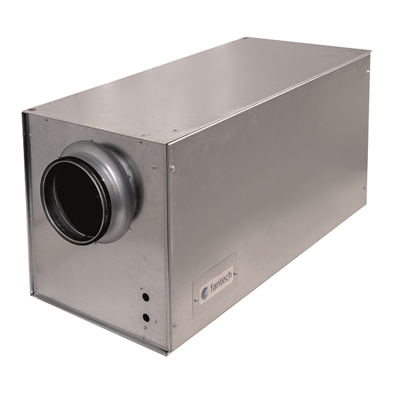
Speak to Fantech for more information on how to install the Introduction product in different installation locations. Product Description Fantech Warranty This product is a galvanized, sheet metal rectangular box with an 8–10 inch duct inlet and outlet and an electronically commutated (EC) motor. -
Page 4: Name Plate
Name Plate Note: Make sure the product’s voltage corresponds to the motor name plate. DOM: JUL 30, 2024 MO#: 1234567890 Model: MUAS Item#: Volts: Phase: Amps: Max. Temp. CFM: 0.20" w.c. Power rating: Made in USA with AIRFLOW Global Components Fantech Logo 10. -
Page 5: Safety Instructions
Safety Instructions Personal protective equipment Note: Use personal protective equipment during all work on the To decrease the risk of fire, electric shock, or injury, read product. and obey these warning instructions before you do work • Approved eye protection on the product: •... -
Page 6: Installation
Installation To Do Before the Installation of the Product You can use this product to replace kitchen exhaust air or other continuously or intermittently operating powered ex- haust systems. A makeup air heater (MUAH) is offered as an accessory to temper the incoming supply air from the product. -
Page 7: To Do Before The Installation Of The Duct Run
sure the entire length of the connected duct work is insu- lated to prevent condensation. • Make sure the air that enters the gas/oil heat exchangers is a minimum of 55°F (12.8°C) and air that touches water pipes or water coils will not freeze them. •... -
Page 8: To Install The Product
• Upstream from the exhaust outlet. • A minimum of 3 ft. (1 m.) away from dryer vents and forced air system exhaust (medium or high efficiency systems), driveways, oil fill pipes, gas meters, or garbage containers. • A minimum of 18 in. (460 mm.) above the ground, or above the level of expected snowfall (if applicable). -
Page 9: To Attach The Duct Without Mounting Clamps
FC Mounting Clamps Fig. 6 Vertical Wall-mount Position If you install the product near a duct bend, do these Air inlet steps to prevent vibrations, unwanted noise, and de- creased air pressure: Threaded screw Measure the distance (A) between the product and C. -
Page 10: To Install The Temperature
Note: The sensor measures air velocity in the duct. If it is less than 100 ppm, the coil will not heat the air. Note: The MUAH does not come with a disconnect switch. Turn off the power supply from the main electrical panel (circuit breaker) before you service the heater. -
Page 11: Electrical Connection
Electrical connection To Connect the Product to the Power Supply Note: The transducer must be close to the exhaust fan or a dedi- cated circuit. Install the FMAC’s current transducer onto the neutral leg of the compensated exhaust fan (by others) wires. Electronic Air Velocity Sensor Install low voltage wire between the current transducer and the FMAC. -
Page 12: Operation
Operation Sequence of Operations When the FMAC receives a signal from the current trans- To Operate the Product ducer that the compensated exhaust system is energized, the FMAC outputs will activate. Caution The FMAC will supply a 24VAC signal to power the motorized damper (if applicable) to the open position. -
Page 13: Commissioning
If airflow comes in, the house is under negative pressure. Commissioning Increase the speed of the MUAS with the “HT” trim pot. With the “LT” trim pot, do this procedure again with the To Do Before the compensated exhaust system on low speed. Commissioning Once both the “HT”... -
Page 14: Technical Data
Technical data Technical Data Overview Max. temperature of transported air, °F IP class Refer to the data sheet on the online catalogue at Fantech.net. Voltage, current, frequency Refer to the nameplate. Refer to section 1.6 Name Plate for more information. Motor data Refer to the motor nameplate or the technical documentation from the motor manufacturer. - Page 15 Note: Only one conductor can be looped through the center of the current transducer neutral line. Note: High voltage wires are shown by solid lines (115–120 Vac). Low voltage wires are shown by dashed lines (5–24 Vac/Vdc). Note: All wire connections are by others. Wire terminations are contained in each component’s installation instructions. Makeup Air Fan Transformer WAGO...
-
Page 16: Product Dimensions
Product Dimensions Fig. 12 MUAS Dimensions Note: Dimensions are given in inches (mm). 18 (457) 8 (203) 10 (254) 2 3/4 (70) 38 1/4 (972) 20 (508) #474049, MUAS 8 #474050, MUAS 10 18 (457) 10 (254) 10 (254) 2 3/4 (70) 38 1/4 (972) 20 (508) - Page 17 Fig. 13 Accessory — LD Duct Silencer Dimensions Note: Dimensions are given in inches (mm). 8 (203) 8 (203) 23 5/8 (594) LD 8 10 (254) 9 (229) 35 1/2 (902) LD 10...
- Page 18 Fig. 14 Accessory — FML Intake Hood Dimensions Note: Dimensions are given in inches (mm). 5 (127) 3 1/2 (89) 9 (229) 9 (229) 8 (203) FML 8 6 (152) 3 1/2 (89) 11 (279) 11 (279) 10 (254) FML 10 12 (305) 13 (330) 13 (330)
- Page 19 Fig. 15 Accessory — ADC Shut-off Damper Dimensions Note: Dimensions are given in inches (mm). 8 (203) 10 (254) ADC 8 10 (254) 10 (254) ADC 10...
- Page 20 Fig. 16 Accessory — MUAH Duct Heater Dimensions Note: Dimensions are given in inches (mm). 10 1/8 11 7/8 8 (203) 9 1/4 (235) 15 (381) 2 (51) 7/8 (22) MUAH 8/6 (257) (302) 11 1/4 17 1/4 10 1/8 11 7/8 10 (254) 2 (51)
- Page 22 last page Canada Latin America (800) 747 1762 (800) 565 3548 +52 55 1328 7328 support@fantech.net support@fantech.net support@fantech.net © Copyright Fantech All rights reserved Fantech reserves the rights to alter their products without notice. This also applies to products already ordered, as long as it does not affect the previously agreed specifications.
Need help?
Do you have a question about the fantech MUAS 8 and is the answer not in the manual?
Questions and answers