Table of Contents
Advertisement
Quick Links
RX660 Group
16
32
RENESAS 32-Bit MCU
RX Family/RX600 Series
All information contained in these materials, including products and product specifications, represents
information on the product at the time of publication and is subject to change by Renesas Electronics
Corp. without notice. Please review the latest information published by Renesas Electronics Corp.
through various means, including the Renesas Electronics Corp. website (http://www.renesas.com).
www.renesas.com
Target Board for RX660
User's Manual
Rev.1.00 2022.Mar
Advertisement
Table of Contents

Related Manuals for Renesas RX660 Series


Summary of Contents for Renesas RX660 Series
- Page 1 All information contained in these materials, including products and product specifications, represents information on the product at the time of publication and is subject to change by Renesas Electronics Corp. without notice. Please review the latest information published by Renesas Electronics Corp.
- Page 2 Renesas Electronics disclaims any and all liability for any damages or losses incurred by you or any third parties arising from the use of any Renesas Electronics product that is inconsistent with any Renesas Electronics data sheet, user’s manual or other Renesas Electronics document.
- Page 3 Unit Products The following usage notes are applicable to all Microprocessing unit and Microcontroller unit products from Renesas. For detailed usage notes on the products covered by this document, refer to the relevant sections of the document as well as any technical updates that have been issued for the products.
- Page 4 The following documents apply to the Target Board for RX660. Be sure to refer to the latest versions of these documents. The newest versions of the listed documents are available on the Renesas Electronics Web site.
- Page 5 Pmod™ property of Digilent Inc. For the Pmod™ interface specification, refer to the Pmod™ License Agreement page at the Web site of Digilent Inc. Random Access Memory Renesas Flash Programmer Read Only Memory Serial Peripheral Interface UART Universal Asynchronous Receiver/Transmitter Universal Serial Bus All trademarks and registered trademarks are the property of their respective owners.
-
Page 6: Table Of Contents
Table of Contents 1. Overview ..........................7 Package Components ..........................7 Purpose ..............................7 Features ..............................7 Preparation ..............................7 Target Board for RX660: Table of Specifications ..................8 Block Diagram ............................9 2. Board Layout ........................10 3. Parts Layout ........................11 4. -
Page 7: Overview
User’s Manual 1. Overview Package Components Thank you for purchasing the Target Board for RX660 evaluation tool from Renesas (hereinafter referred to as “this product”). This product consists of the Target Board for RX660 (RTK5RX6600C00000BJ). Purpose This product is an evaluation tool for a Renesas MCU. This user’s manual describes the hardware specifications, ways of setting switches, and the basic setup procedure. -
Page 8: Target Board For Rx660: Table Of Specifications
Target Board for RX660 1. Overview Target Board for RX660: Table of Specifications Table 1-1 shows the specifications of this product. Table 1-1 Target Board for RX660 Specification Table Item Specification Part No.: R5F56609BDFP Evaluation MCU Package: 100-pin LFQFP On-chip memory: 1-MB ROM, 128-KB RAM, 32-KB data flash memory Size: 54.0 mm x 90.0 mm Board size Thickness: 1.6 mm... -
Page 9: Block Diagram
Target Board for RX660 1. Overview Block Diagram Figure 1-1 shows the block diagram of this product. MCU header x 2 connector Pattern for cutting Pmod Emulator circuit Evaluation MCU connector External power- supply header Power Reset switch indicator Main clock User switch User LED x 2 Note: Gray shading of blocks indicates parts that are not mounted on the board. -
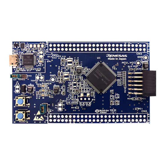
Page 10: Board Layout
Target Board for RX660 2. Board Layout 2. Board Layout Figure 2-1 shows the external appearance of the top side of this product. ACT LED MCU headers Current USB connector measurement header Evaluation MCU Power indicator Pmod connector External power- supply header User LED User switch... -
Page 11: Parts Layout
Target Board for RX660 3. Parts Layout 3. Parts Layout Figure 3-1 shows the parts layout of this product. 90.0mm Figure 3-1 Parts Layout R20UT5068EJ0100 Rev.1.00 Page 11 of 28 Mar.01.2022... -
Page 12: Operating Environment
4. Operating Environment Figure 4-1 shows the operating environment of this product. Install the IDE from the following URL on the host PC. The installer automatically installs all required drivers along with the IDE. https://www.renesas.com/development-tools USB cable Target Board for RX660... -
Page 13: User Circuits
USB Connector The shape of the connector is USB micro-B for the IDE and for the Renesas Flash Programmer (RFP). Connect the connector to the computer by a USB cable. If the power supply on the host side is on, the power is supplied to this product at the same time as connection of the cable. -
Page 14: External Power-Supply Header
Target Board for RX660 5. User Circuits External Power-Supply Header When the evaluation MCU is to have a desired power-supply voltage, or when more current is required than the USB is capable of supplying, use the external power-supply header (J4) to supply power. The usable voltages depend on the evaluation MCU. -
Page 15: Pmod Connector
Target Board for RX660 5. User Circuits Pmod Connector The specification of the Pmod connector (CN1) is on the assumption that Pmod modules are to be connectable. CN1 is for connection to Pmod Interface Type 6A (Type 6 + Type 1) modules* in the product as shipped. Remodeling of the board by removing patterns for cutting enables the connection of CN1 to Type 2A or Type 3A modules. -
Page 16: Current Measurement Header
Target Board for RX660 5. User Circuits Figure 5-3 Circuit Schematic for the Pmod Connector Current Measurement Header The current measurement header (J5) is used to measure the current drawn by the evaluation MCU (an actual header component is not mounted on the board as shipped). The current drawn can be measured by connecting an ammeter to the evaluation MCU. -
Page 17: Reset Switch
Target Board for RX660 5. User Circuits 5.10 Reset Switch Pressing the RESET switch applies a hardware reset to the evaluation MCU. 5.11 User Switch An optional user switch (SW1) is mounted. It is connected to pin 16 of the evaluation MCU, which operates as pin function P34. -
Page 18: Power-Supply Selection Header
Target Board for RX660 5. User Circuits 5.14 Power-Supply Selection Header The operating voltage of the evaluation MCU can be set to 5 V or 3.3 V. Mount the header (J3) and remove the resistor (R52) to change the operating voltage. (5 V setting at the time of shipment) Note: When changing the setting, be careful not to short-circuit 5 V and 3.3 V. -
Page 19: Configurations
Target Board for RX660 6. Configurations 6. Configurations Modifying the Target Board for RX660 This section describes how to change the setting of this product by using option-link resistors and jumpers. An option-link resistor is a 0-Ω surface-mount resistor, which is used to short-circuit or isolate a part of circuits. The subsequent sections contain lists of option-link resistors for individual functions. -
Page 20: On-Chip Oscillator
Target Board for RX660 6. Configurations On-Chip Oscillator Table 6-3 show the option-link resistors for the operation of the on-chip oscillator. Table 6-3 Option-Link Resistors for the HOCO Setting of the HOCO Mounted Not Mounted Remark Oscillating R18, R19 R20, R23 ... -
Page 21: Handling Precautions
Target Board for RX660 7. Handling Precautions 7. Handling Precautions Adding Load When adding loads by USB power supply, the maximum operational current is as follows. Details for resetting the emulator circuit, refer to section 5.13. When the emulator circuit is in the non-reset state, the maximum operational current is 300 mA at 3.3 V, ... - Page 22 Target Board for RX660 7. Handling Precautions Table 7-1 Power-Supply and Usage Conditions Power-Supply Usage Condition Power Use of boards Use of an emulator Remodeling the board supplied to supported by and IDE the RX660 Pmod* 5 V (VBUS) Possible Possible Not required (default)
-
Page 23: Developing Code
Target Board for RX660 8. Developing Code 8. Developing Code Using the e studio Figure 8-1 shows the settings of the e studio when creating a new project for the Target Board for RX660. [Debug hardware]: Select [E2 Lite (RX)]. •... -
Page 24: Using Cs
Target Board for RX660 8. Developing Code Using CS+ Figure 8-2 and Figure 8-3 show the settings of CS+ when creating a new project for the Target Board for RX660. [Using Debug Tool]: • Select [RX E2 Lite] from [Using Debug Tool] in the [Debug] menu. Figure 8-2 Panel for Selecting the Debug Tool [Power target from the emulator]: Select [No]. -
Page 25: Additional Information
Copyright This document may be, wholly or partially, subject to change without notice. All rights reserved. Duplication of this document, either in whole or part is prohibited without the written permission of Renesas Electronics Corporation. © 2022 Renesas Electronics Corporation. All rights reserved. - Page 26 Revision History Target Board for RX660 User’s Manual Rev. Date Description Page Summary 1.00 Mar.01.2022 First Edition issued...
- Page 27 Target Board for RX660 User’s Manual Publication Date: Rev.1.00 Mar.01.2022 Published by: Renesas Electronics Corporation...
- Page 28 RX660 Group R20UT5068EJ0100...
Need help?
Do you have a question about the RX660 Series and is the answer not in the manual?
Questions and answers