
Related Manuals for Advantech PCA-6189


Summary of Contents for Advantech PCA-6189
- Page 1 PCA-6189 Full-sized PCI/ISA-bus socket 479 Pentium® M/ Celeron® M processor-based CPU card User’s Manual Download from Www.Somanuals.com. All Manuals Search And Download.
- Page 2 Copyright Notice This document is copyrighted, 2005, by Advantech Co., Ltd. All rights are reserved. Advantech Co., Ltd. reserves the right to make improve- ments to the products described in this manual at any time without notice. No part of this manual may be reproduced, copied, translated or transmit- ted in any form or by any means without the prior written permission of Advantech Co., Ltd.
- Page 3 Advantech equipment is destined for the laboratory or the factory floor, you can be assured that your product will provide the reliability and ease of operation for which the name Advantech has come to be known. Your satisfaction is our primary concern. Here is a guide to Advantech’s customer services.
- Page 4 PCA-6189 User’s Manual Download from Www.Somanuals.com. All Manuals Search And Download.
- Page 5 Table 1.2: PCA-6189 DDR memory compatibility table Vendor Size Speed Type Model Memory Apacer 256MB DDR266 77.10603 Infineon .112 HYB25D25680B T-7(32×8) Kingston 256MB DDR266 Nanya NT5DS32MBAT- 256MB DDR266 "KVR256 "Kingston X64C25/ D328DM- 60(32×8) 512MB DDR266 KVR266 Kingston X64C25/ D328DL- 60(32×8)
- Page 6 .465 K4H560838E- TCCC 512MB DDR400 77.10736 Infineon .114 HYB25D256800 BT-5 512MB DDR400 77.10736 Mosel .56G V58C2256804SA 512MB DDR400 77.10736 SAMSUNG .464 K4H560838E- TCCC DDR400 77.11136 SAMSUNG .464 K4H510838B- TCCC PCA-6189 User’s Manual Download from Www.Somanuals.com. All Manuals Search And Download.
- Page 7 DDR400 Hynix HY5DU56822CT -D43 Transcend 256MB DDR400 Mosel V58C22568004S 512MB DDR400 Mosel V58C22568004S * PCA-6189 only supports DDR333 RAM. If DDR400 RAM is used, it will operate at the speed of DDR333 Download from Www.Somanuals.com. All Manuals Search And Download.
- Page 8 Advantech assumes no liability under the terms of this warranty as a consequence of such events. If an Advantech product is defective, it will be repaired or replaced at no charge during the warranty period. For out-of-warranty repairs, you will be billed according to the cost of replacement materials, service time and freight.
- Page 9 It should be free of marks and scratches and in perfect working order upon receipt. As you unpack the PCA-6189, check it for signs of shipping damage. (For example, damaged box, scratches, dents, etc.) If it is damaged or it fails to meet the specifications, notify our service department or your local sales representative immediately.
- Page 10 1.0.3 Release Note Date Revision Description December 2004 1st. Edition Initial Release PCA-6189 User’s Manual Download from Www.Somanuals.com. All Manuals Search And Download.
- Page 11 Important Safety Information SAFETY INSTRUCTIONS This device complies with the requirements in part 15 of the FCC rules: Operation is sub- ject to the following two conditions: This device may not cause harmful interference, and This device must accept any interference received, including interference that may cause undesired operation This equipment has been tested and found to comply with the limits for a Class A digital device, pursuant to Part 15 of the FCC Rules.
- Page 12 PCA-6189 User’s Manual Download from Www.Somanuals.com. All Manuals Search And Download.
-
Page 13: Table Of Contents
Board Layout: Jumper and Connector Location ....8 Figure 1.1:Jumper and Connector locations ....8 Figure 1.2:I/O Connectors ..........9 Figure 1.3:SCSI daughter board ........9 PCA-6189 Block Diagram ..........10 Figure 1.4:Block Diagram ..........10 Safety Precautions ............11 Jumper Settings ............... 12 1.8.1... - Page 14 3.4.9 Boot UP Floppy Seek ........... 35 3.4.10 Boot Up NumLock Status..........35 3.4.11 Gate A20 Option............35 3.4.12 Typematic Rate Setting..........35 3.4.13 Typematic Rate (Chars/Sec) ......... 35 PCA-6189 User’s Manual Download from Www.Somanuals.com. All Manuals Search And Download.
- Page 15 3.4.14 Typematic Delay (msec)..........35 3.4.15 Security Option ............. 36 3.4.16 APIC Mode ..............36 3.4.17 MPS Version Control For OS........36 3.4.18 OS Select For DRAM > 64MB ........36 3.4.19 Report No FDD For WIN 95 ........36 3.4.20 Small Logo(EPA) Show ..........
- Page 16 3.12.3 Current CPU Temperature ..........48 3.12.4 Current CPUFAN Speed..........48 3.12.5 VCORE, VBAT(V), 5VSB(V) ........48 3.12.6 Shutdown Temperature..........48 3.13 Frequency/Voltage Control ..........48 Figure 3.12:Spread Spectrum Control screen ....48 PCA-6189 User’s Manual Download from Www.Somanuals.com. All Manuals Search And Download.
- Page 17 3.13.1 Auto-detect PCI CLK ........... 48 3.13.2 Spread Spectrum ............48 3.14 Passwords and Settings ........... 49 3.14.1 Load Setup Defaults............49 3.14.2 Set Supervisor Password..........49 3.14.3 Set User Password ............49 3.14.4 Save & Exit Setup............49 3.14.5 Exit Without Saving............49 Chapter 4 Chipset Software Install Utility.....52 Before you begin .............
- Page 18 Table B.10:External keyboard connector (CN12) ..116 B.11 Power LED (CN16)............116 Table B.11: CPU Fan Power Connector (CN14)..116 B.12 Power LED (CN16)............117 Table B.12:Power LED (CN16) ......... 117 PCA-6189 User’s Manual xviii Download from Www.Somanuals.com. All Manuals Search And Download.
- Page 19 B.13 External Speaker Connector (CN17)......117 Table B.13:External Speaker Connector (CN17) ..117 B.14 Reset Connector (CN18) ..........118 Table B.14:Reset connector (CN18)......118 B.15 ATX Feature Connector (CN20)........118 Table B.15:HDD LED connector (CN19) ....118 B.16 ATX Feature Connector (CN20)........119 Table B.16:ATX Feature Connector (CN20) .....
- Page 20 PCA-6189 User’s Manual Download from Www.Somanuals.com. All Manuals Search And Download.
- Page 21 General Information Download from Www.Somanuals.com. All Manuals Search And Download.
-
Page 22: Chapter 1 Hardware Configuration
Gigabit Ethernet ports, Serial/parallel ATA ports, and a PCI- X (64-bit / 66Mhz) bus. With the compliance with PICMG 1.0 specifica- tion, PCA-6189 can be used with wide choice of existing PCI/ISA back- planes to meet versatile requirements of industrial applications. -
Page 23: Features
Note: Some of the features mentioned above are not available with all models. For more information about the specifications of a particular model, see Table 1.1 : Comparison table and Section 1.3: Specifications. 1.2 Features Supports FSB 400 MHz low thermal profile Intel® Pentium® M processor or Intel®... -
Page 24: Memory
• AC-97 Audio: PCA-6189 can provide audio function with the optional audio extension module PCA-AUDIO-00A1 • USB ports: PCA-6189 supports up to four USB 2.0 ports with trans- mission rates up to 480Mbps; available on the I/O bracket (dual layer brackets only) or through the two-USB-port cable (P/N: 1700100170) for single layer version. -
Page 25: Ethernet Lan
• Board weight: 0.5 kg (1.2 lb) 1.4 Jumpers and Connectors Connectors on the PCA-6189 single board computer link it to external devices such as hard disk drives and a keyboard. In addition, the board has a number of jumpers used to configure your system for your applica- tion. - Page 26 CN13 Reserved CN14 CPU FAN connector CN16 Power LED CN17 External speaker CN18 Reset connector CN19 HDD LED connector CN20 ATX feature connector CN21 ATX soft power switch (PS_ON) PCA-6189 User’s Manual Download from Www.Somanuals.com. All Manuals Search And Download.
- Page 27 Table 1.2: Connectors CN22 HW Monitor Alarm Close: Enable OBS Alarm Open: Disable OBS Alarm CN27 Extension I/O board connector CN28 Extension I/O board connector CN29 SM BUS Connector PIN1: SMB_DATA PIN2: SMB_CLOCK CN30 Extension PCI connector (for SCSI daughter board) CN31 USB port 0,1 CN32...
-
Page 28: Board Layout: Jumper And Connector Location
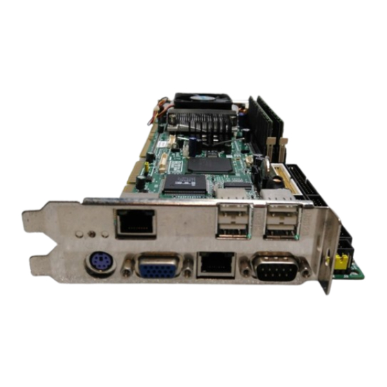
1.5 Board Layout: Jumper and Connector Location Figure 1.1: Jumper and Connector locations PCA-6189 User’s Manual Download from Www.Somanuals.com. All Manuals Search And Download. - Page 29 Figure 1.2: I/O Connectors 68 Pin for Ultra 160 50 Pin for Ultra wide SCSI Adaptec AIC-7899 68 Pin for Ultra 160 Figure 1.3: SCSI daughter board Download from Www.Somanuals.com. All Manuals Search And Download.
-
Page 30: Pca-6189 Block Diagram
1.6 PCA-6189 Block Diagram Figure 1.4: Block Diagram PCA-6189 User’s Manual Download from Www.Somanuals.com. All Manuals Search And Download. -
Page 31: Safety Precautions
Notice: Before install your PCA-6189 into a chassis, make sure that all components on both sides of the CPU card do not touch any metal parts, especially the chassis wall and add-on card at the adjacent slot. -
Page 32: Jumper Settings
* default setting 1.8.3 Watchdog timer output (J2) The PCA-6189 contains a watchdog timer that will reset the CPU or send a signal to IRQ11 in the event the CPU stops processing. This feature means the PCA-6189 will recover from a software failure or an EMI problem. -
Page 33: System Memory
It will be held low until the watchdog timer is reset. 1.9 System Memory The PCA-6189 has two sockets for 184-pin dual inline memory modules (DIMMs). All these sockets use 2.5 V unbuffered double data rate synchronous DRAMs (DDR SDRAM). -
Page 34: Cpu Fsb And Memory Speed
1.9.1 CPU FSB and memory speed The PCA-6189 can accept DDR SDRAM memory chips without parity. Also note: The PCA-6189 accepts PC2100 (DDR266), PC2700 (DDR 333) and DDR SDRAM, depending on the CPU front side bus frequency (FSB). Please refer to the table below for the relationship between the CPU FSB and memory speed. - Page 35 Warning: Without a fan or heat sink, the CPU will over-heat and cause damage to both the CPU and the single board computer. To install a CPU, first turn off your system and remove its cover. Locate the processor socket 479. 1.
- Page 36 PCA-6189 User’s Manual Download from Www.Somanuals.com. All Manuals Search And Download.
- Page 37 Connecting Peripherals Chapter 2 Download from Www.Somanuals.com. All Manuals Search And Download.
-
Page 38: Chapter 2 Connecting Peripherals
2.2 1st & 2nd (CN1, CN2) IDE Connectors You can attach up to four IDE (Integrated Drive Electronics) drives to the PCA-6189’s built-in controller. The primary (CN1) and secondary (CN2) connectors can each accommodate two drives. Wire number 1 on the cable is red or blue and the other wires are gray. -
Page 39: Floppy Drive Connector (Cn3)
2.3 Floppy Drive Connector (CN3) You can attach up to two floppy disk drives to the PCA-6189's on board controller. You can use 3.5" (720 KB, 1.44 MB) drives. The single board computer comes with a 34-pin daisy-chain drive con- nector cable. -
Page 40: Parallel Port (Cn4)
2.4 Parallel Port (CN4) The parallel port is normally used to connect the single board computer to a printer. The PCA-6189 includes an onboard parallel port, accessed through a 26-pin flat-cable connector, CN4. The card comes with an adapter cable which lets you use a traditional DB-25 connector. The cable has a 26-pin connector on one end and a DB-25 connector on the other, mounted on a retaining bracket. -
Page 41: Usb Ports Cn6, Cn31, And Cn32
2.5 USB Ports CN6, CN31, and CN32 The PCA-6189 provides up to four ports for the USB (Universal Serial Bus) interface, which gives complete Plug & Play and hot swapping for up to 127 external devices.The USB interface complies with USB Speci- fication Rev. -
Page 42: Vga Connector Cn7
VGA. Pin assignments for CRT connector CN7 are detailed in Appendix B. 2.7 LVDS connector VCN2 The PCA-6189 provides a LVDS interface that supports 18-bit LCD pan- els. Pin assignments for the LVDS connector VCN2 are detailed in Appendix B. -
Page 43: Dvi Connector Vcn3
VCN3 are detailed in Appendix B. 2.9 Ethernet Connector (CN8 and CN34) The PCA-6189 is equipped with single/dual high-performance 32-bit PCI-bus Ethernet interface, which is fully compliant with IEEE 802.3/u 10/100Mbps CSMA/CD and IEEE 802.3ab 1000Base-T standards. It is supported by all major network operating systems and is 100% Novell NE-2000 compatible. -
Page 44: Serial Ports (Com1 : Cn9; Com2 : Cn10 )
2.10 Serial Ports (COM1 : CN9; COM2 : CN10 ) The PCA-6189 offers two serial ports, CN9 as COM1 and CN10 as COM2. These ports can connect to serial devices, such as a mouse or a printer, or to a communications network. -
Page 45: External Keyboard Connector (Cn12)
2.12 External Keyboard Connector (CN12) CN12 In addition to the PS/2 mouse/keyboard connector on the PCA-6189's rear plate, there is also an extra onboard external keyboard connector. This gives system integrators greater flexibility in designing their sys- tems. 2.13 CPU Fan Connector (CN14) -
Page 46: Front Panel Connectors (Cn16, 17, 18, 19, 21&29)
2.14 Front Panel Connectors (CN16, 17, 18, 19, 21&29) There are several external switches to monitor and control the PCA-6189 CN18 CN21 CN19 CN29 CN17 CN16 2.14.1 Power LED (CN16) CN16 is a 5-pin connector for the power on LED. Refer to Appendix B for detailed information on the pin assignments. -
Page 47: Reset (Cn18)
2.14.6 SM Bus Connector (CN29) This connector is reserved for Advantech's SNMP-1000 HTTP/SNMP Remote System Manager. The SNMP-1000 allows users to monitor the internal voltages, temperature and fans from a remote computer through an Ethernet network. -
Page 48: Atx Feature Connector (Cn20)
2.15 ATX feature connector (CN20) CN20 Connect to the CN1 on the Advantech backplane to enable the ATX func- tion, 5V stand-by. 2.16 AC-97 Audio interface (CN43) CN43 The PCA-6189 provides AC-97 audio through PCA-AUDIO-00A1 module from Advantech. PCA-6189 User’s Manual... -
Page 49: Serial Ata Interface (Sa0 And Sa1)
2.17 Serial ATA interface (SA0 and SA1) SA0 & SA1 In addition to the two EIDE interfaces (up to four devices), the PCA-6189 features high performance serial ATA interface (up to 150MB/s) which eases cabling to hard drives with thin and long cables. -
Page 50: Auxiliary 4-Pin Power Connector (Atx1)
To ensure the sufficiency of power supply for Pentium M or Celeron M single board computer, one auxiliary 4 pin power connector is available on PCA-6189. This connector must be connected to the power supply, otherwise system might be unstable. - Page 51 Award BIOS Setup Chapter 3 Download from Www.Somanuals.com. All Manuals Search And Download.
-
Page 52: Chapter 3 Award Bios Setup
Then enter the "Setup" screen to modify the data. If the "CMOS checksum error..." message appears again and again, please check to see if you need to replace the battery in your system. PCA-6189 User’s Manual Download from Www.Somanuals.com. All Manuals Search And Download. -
Page 53: Entering Setup
3.2 Entering Setup Turn on the computer and press <Del> to enter the BIOS setup. Figure 3.1: Award BIOS Setup initial screen 3.3 Standard CMOS Setup Choose the Standard CMOS Features option from the initial setup screen menu to display the screen below. This menu allows you to configure sys- tem components such as date, time, hard disk drive, floppy drive, display, and memory. -
Page 54: Advanced Bios Features
The Advanced BIOS Features screen appears when you choose the Advanced BIOS Features item from the initial setup screen menu. Use this screen to configure the PCA-6189 according to your particular requirements. Below are some major items that are provided in the Advanced BIOS Features screen. -
Page 55: Quick Power On Self Test
3.4.5 Quick Power On Self Test This setting allows the system to skip certain tests while booting. This will decrease the time needed to boot the system. 3.4.6 First/Second/Third Boot Device The BIOS will load the OS with the devices in the sequence selected. The sequence includes: Floppy, LS120, HDD-0, SCSI, CDROM, HDD-1, HDD-2, HDD-3, ZIP100, USB-FDD, USB-ZIP, USBCDROM, USB- HDD, LAN, and Disabled. -
Page 56: Security Option
BIOS option to if you are using other operating systems. 3.4.20 Small Logo(EPA) Show This setting controls whether or not the EPA logo is shown. The choices are Disabled or Enabled. PCA-6189 User’s Manual Download from Www.Somanuals.com. All Manuals Search And Download. -
Page 57: Advanced Chipset Features
3.5 Advanced Chipset Features By choosing the Advanced Chipset Features option from the Initial Setup Screen menu, the screen below will be displayed. This sample screen contains the manufacturer’s default values for the PCA-6189, as shown in Figure 3-4: Note:... -
Page 58: Dram Ras# To Cas# Delay
This setting controls the length of time to lower the CPU speed when CPU temperature is too high. The choices are: 4 Min, 8 Min, 16 Min, and 32 Min. PCA-6189 User’s Manual Download from Www.Somanuals.com. All Manuals Search And Download. -
Page 59: Agp Aperture Size (Mb)
3.5.12 AGP Aperture Size (MB) Use this setting to select the size of the Accelerated Graphics Port (AGP) aperture. The aperture is a portion of the PCI memory address range ded- icated to graphics memory address space. Host cycles that hit the aperture range are forwarded to the AGP without any translation. -
Page 60: Integrated Peripherals
3.7.1 IDE DMA transfer access This setting controls the DMA function of hard disk drive. The choices are Enabled or Disabled. Choose Enabled to assign the IDE DMA func- tion. PCA-6189 User’s Manual Download from Www.Somanuals.com. All Manuals Search And Download. -
Page 61: On-Chip Ide Device
3.7.2 On-Chip IDE Device IDE Primary (Secondary) Master/Slave PIO/UDMA Mode (Auto) Each channel (Primary and Secondary) has both a master and a slave, making four IDE devices possible. Because each IDE device may have a different Mode timing (0, 1, 2, 3, 4), it is necessary for these to be independent. The default setting Auto will allow auto-detection to ensure optimal per- formance. -
Page 62: Usb Controller
3.8.6 On-board LAN2 Control The options for this setting are Enabled and Disabled. Select Disable if you don’t want to use the onboard LAN controller2. 3.9 SuperIO Device Figure 3.8: SuperIO Device PCA-6189 User’s Manual Download from Www.Somanuals.com. All Manuals Search And Download. - Page 63 3.9.1 On-board FDC Controller When enabled, this field allows you to connect your floppy disk drives to the onboard floppy disk drive connector instead of a separate controller card. If you want to use a different controller card to connect the floppy disk drives, set this field to Disabled.
- Page 64 3.10.2 Power Management This option allows you to select from Min Saving, Max Saving, or User Defined to set the degree of power saving. If you select Min Saving or PCA-6189 User’s Manual Download from Www.Somanuals.com. All Manuals Search And Download.
- Page 65 Max Saving, the values for HDD Power Down and Suspend Mode (the following settings) are filled in automatically. If you select User Defined, you must also enter values for HDD Power Down and Suspend Mode. Table 3.1: Power Management settings Min Saving For minimum power usage, sets Suspend Mode to 1 hour and set HDD Power Down to 15 minutes.
- Page 66 When this value is set to Enabled, the system will resume from suspend mode if an interruption occurs. The choices are Enabled and Disabled. 3.11 PnP/PCI Configurations Figure 3.10: PnP/PCI configurations screen PCA-6189 User’s Manual Download from Www.Somanuals.com. All Manuals Search And Download.
- Page 67 3.11.1 PNP OS Installed Set this option to Yes if PNP OS is installed on your system. The default value for this setting is No. 3.11.2 Reset Configuration Data Default is Disabled. Select Enable to reset Extended System Configura- tion Data (ESCD) if you have installed a new add-on and system configu- ration has caused such a conflict that the OS cannot boot.
-
Page 68: Auto-Detect Pci Clk
Use this function to tune the PCI clock frequency. Setting this option to Disabled will limit the clock signal spread, increase the consistency of the frequency, but increase the EMI. Setting this option to Enabled will decrease the EMI. PCA-6189 User’s Manual Download from Www.Somanuals.com. All Manuals Search And Download. -
Page 69: Passwords And Settings
3.14 Passwords and Settings 3.14.1 Load Setup Defaults Choose the Load Setup Defaults selection from the initial setup screen. At the prompt, enter Y to return system setup options to default values. 3.14.2 Set Supervisor Password Choose the Set Supervisor Password selection from the initial setup screen. - Page 70 PCA-6189 User’s Manual Download from Www.Somanuals.com. All Manuals Search And Download.
- Page 71 Chipset Software Installation Utility Chapter 4 Download from Www.Somanuals.com. All Manuals Search And Download.
-
Page 72: Chapter 4 Chipset Software Install Utility
To facilitate the installation of the enhanced display device drivers and utility software, you should read the instructions in this chapter carefully before you attempt installation. The device drivers for the PCA-6189 board are located on the software installation CD. The auto-run function of the driver CD will guide and link you to the utilities and device drivers under a Windows system. -
Page 73: Windows Xp Driver Setup
• Identification of Intel chipset components in the Device Manager. • Integrates superior video features. These include filtered sealing of 720 pixel DVD content, and MPEG-2 motion compensation for soft- ware DVD Note: This utility is used for the following versions of Windows system, and it has to be installed before installing all the other drivers: Windows 98SE Windows 2000, Windows ME, Windows... - Page 74 Click "Next" when you see the following message. Click "Yes" when you see the following message. PCA-6189 User’s Manual Download from Www.Somanuals.com. All Manuals Search And Download.
- Page 75 Click "Next" when you see the following message. When the following message appears, click "Finish" to complete the installation and restart Windows. Chapter 4 Download from Www.Somanuals.com. All Manuals Search And Download.
- Page 76 PCA-6189 User’s Manual Download from Www.Somanuals.com. All Manuals Search And Download.
- Page 77 VGA Setup Chapter 5 Download from Www.Somanuals.com. All Manuals Search And Download.
-
Page 78: Chapter 5 Vga Setup
Chapter 5 VGA Setup 5.1 Introduction The PCA-6189 has VGA onboard, you need to install the VGA driver to enable the function. The Intel 855GME Chipset provides a highly integrated graphics acceler- ator delivering high performance 2D, 3D, and video capabilities. With its interfaces to UMA using a DVMT configuration, an analog display, a LVDS port, and two digital display ports (e.g. -
Page 79: Windows Xp Driver Setup
5.3 Windows XP Driver Setup Note: Before installing this driver, make sure the CSI utility has been installed in your system. See Chapter 4 for information on installing the CSI utility Insert the driver CD into your system's CD-ROM drive. In a few seconds, the software installation main menu appears, as shown in the following figure. - Page 80 You will see a welcome window. Please chick on "Next" to con- tinue the installation. PCA-6189 User’s Manual Download from Www.Somanuals.com. All Manuals Search And Download.
- Page 81 Click "Yes" when you see the following message. Click on "Yes" to continue the installation Chapter 5 Download from Www.Somanuals.com. All Manuals Search And Download.
- Page 82 Click "Finish" to complete the installation and restart the computer now or later. PCA-6189 User’s Manual Download from Www.Somanuals.com. All Manuals Search And Download.
- Page 83 LAN Configuration Chapter 6 Download from Www.Somanuals.com. All Manuals Search And Download.
-
Page 84: Chapter 6 Lan Configuration
Chapter 6 LAN Configuration 6.1 Introduction The PCA-6189 features the 32-bit 10/100/1000 Mbps Ethernet network interface. This interface supports bus mastering architecture and auto- negotiation features. Therefore standard twisted-pair cabling with RJ-45 connectors for 10 Mbps, 100 Mbps and 1000 Mbps connections can be used. -
Page 85: Installation
See Chapter 4 for information on installing the CSI utility. The PCA-6189's onboard Ethernet interface supports all major network operating systems. However, the installation procedure varies with differ- ent operating systems. In the following sections, refer to the one that pro- vides driver setup procedure for the operating system you are using. - Page 86 Select "I accept the terms in the license agreement" and click "Next" to continue. Click "Next" to continue. PCA-6189 User’s Manual Download from Www.Somanuals.com. All Manuals Search And Download.
- Page 87 Click "Install Software" to start the installation procedure. The driver will be installed automatically and the LAN function will be enabled after the installation Chapter 6 Download from Www.Somanuals.com. All Manuals Search And Download.
- Page 88 PCA-6189 User’s Manual Download from Www.Somanuals.com. All Manuals Search And Download.
- Page 89 SCSI Setup & Configuration Chapter 7 Download from Www.Somanuals.com. All Manuals Search And Download.
-
Page 90: Chapter 7 Scsi Setup & Configuration
Chapter 7 SCSI Setup & Configuration 7.1 Introduction The PCA-6189 is equipped with an Adaptec AIC-7899 single-chip PCI- to-SCSI host adapter which provides a dual channel Ultra 160 multi- tasking interface between your computer.s PCI bus and SCSI devices (disk drives, CD-ROM drives, scanners, tape backups, removable media drives, etc.). -
Page 91: Understanding Scsi
7.2 Understanding SCSI SCSI (pronounced .scuzzy.) stands for Small Computer Systems Inter- face. SCSI is an industry standard computer interface for connecting SCSI devices to a common SCSI bus. A SCSI bus is an electrical pathway that consists of a SCSI interface installed in a computer and one or more SCSI devices. -
Page 92: Terminating The Scsi Bus
I/O rate will decrease. By default, termination on the SCSI controller itself is set to Automatic (the preferred method). We recommend that you do not change this default setting. PCA-6189 User’s Manual Download from Www.Somanuals.com. All Manuals Search And Download. -
Page 93: Configuring The Scsi Interface With Scsiselect
7.5 Configuring the SCSI interface with SCSISelect SCSISelect, included with the CPU card, enables you to change SCSI set- tings without opening the computer. SCSISelect also enables you to low- level format or verify the disk media of your SCSI hard disk drives. The following table lists the available and default settings for each SCSISelect option. - Page 94 Host Adapter BIOS Enabled Enabled Disabled : Not Scan Disabled: Scan Bus Domain Validation2 Enabled, Disabled Enabled Support Removable Disabled Disabled Disks Under BIOS as Boot Only, Fixed Disks2 All Disks PCA-6189 User’s Manual Download from Www.Somanuals.com. All Manuals Search And Download.
-
Page 95: Starting Scsiselect
BIOS Support for Enabled, Disabled Enabled Bootable CD_ROM2 BIOS Support for Enabled, Disabled Enabled Int 13 Extensions2 1 Setting is valid only if Multiple LUN Support is enabled. 2 Settings are valid only if host adapter BIOS is enabled. 7.6 Starting SCSISelect Follow these steps to start SCSISelect: Turn on or restart your system. - Page 96 SCSI ID • Sync Transfer Rate-(Default: 160) Determines the maximum syn- chronous data transfer rate that the SCSI card supports. Use the maxi- mum value of 160 MBytes/sec. PCA-6189 User’s Manual Download from Www.Somanuals.com. All Manuals Search And Download.
- Page 97 • Initiate Wide Negotiation-(Default: Yes) When set to Yes, the SCSI card attempts 16-bit data transfer (wide negotiation.) When set to No, the SCSI card uses 8-bit data transfer unless the SCSI device requests wide negotiation. Note: Set Initiate Wide Negotiation to NO if you are using an 8-bit SCSI device that hangs or exhib- its other performance problems with 16-bit data transfer rate enabled.
- Page 98 (The SCSI Card BIOS is normally enabled by default.) • Domain Validation.(Default: Enabled) Determines the optimal transfer rate for each device on the SCSI bus and sets transfer rates accordingly. Displays the resulting data transfer rate. PCA-6189 User’s Manual Download from Www.Somanuals.com. All Manuals Search And Download.
-
Page 99: Using Scsi Disk Utilities
• Support Removable Disks Under BIOS as Fixed Disks. (Default: Disabled) Determines which removable-media drives are supported by the SCSI card BIOS. Choices are as follows: • Disabled. No removable-media drives are treated as hard disk drives. Software drivers are required because the drives are not controlled by the BIOS. -
Page 100: Installation Under Windows 2000
Then it enter SCSI installation. Please insert SCSI driver floppy disk. 7.9 Windows 9X Driver setup procedure In the window 9x screen, click on “start” and select “setting”. Then click on the “Control Panel” icon to select .System. PCA-6189 User’s Manual Download from Www.Somanuals.com. All Manuals Search And Download. - Page 101 In the “System properties”, choose “PCI SCSI Bus Controller.” Then click on “Properties.” Click on "Update Driver" Chapter 7 Download from Www.Somanuals.com. All Manuals Search And Download.
- Page 102 Click on “Next” Recommend to search for a better driver PCA-6189 User’s Manual Download from Www.Somanuals.com. All Manuals Search And Download.
- Page 103 If the SCSI driver is supplied in floppy disk, click on “Floppy disk drives.” Then, click on “Next.” If the SCSI driver is supplied in CD-ROM disk, click on “Specify a location:" then enter "E:\Drv_SCSI\AIC7899\Windows\Win9X" In the "Update Device Driver Wizard" click on "Next." Chapter 7 Download from Www.Somanuals.com.
- Page 104 The installation is completed. Click on "Finish." Click on "Yes" to restart the system. PCA-6189 User’s Manual Download from Www.Somanuals.com. All Manuals Search And Download.
- Page 105 USB 2.0 Configuration Chapter 8 Download from Www.Somanuals.com. All Manuals Search And Download.
-
Page 106: Chapter 8 Usb 2.0 Configuration
Chapter 8 USB 2.0 Configuration 8.1 Introduction The PCA-6189 is designed with Intel 6300ESB which supports both USB 1.1 and USB 2.0 high-speed transmission. It still remains the compatibil- ity with today's USB device. High-speed USB 2.0 provides data transfer up to 480Mb/s which is 40 times faster than USB 1.1. - Page 107 Onboard Security Setup Chapter 9 Download from Www.Somanuals.com. All Manuals Search And Download.
-
Page 108: Chapter 9 Onboard Security Setup
The PCA-6189's hardware monitor is designed with Winbond W83627HF. Onboard security (OBS) functions monitor key hardware. They help you maintain your system's stability and durability. The PCA-6189 can monitor 5 sets of system positive voltages, 2 sets of system negative voltages, CPU cooling fan speed, and CPU temperature. -
Page 109: Windows Xp Driver Setup
9.2 Windows XP Driver Setup Insert the driver CD into your system's CD-ROM drive. In a few seconds, the software installation main menu appears, as shown in the following figure. Click on the "Install" button under the "OBS DRIVERS" heading. Click "Next"... - Page 110 Click "Next" when you see the following message. Click "Next" when you see the following message. Click "Next" to continue. PCA-6189 User’s Manual Download from Www.Somanuals.com. All Manuals Search And Download.
-
Page 111: Using The Obs Hardware Doctor Utility
Click "Finish" when you see the following message. 9.3 Using the OBS Hardware Doctor Utility After completing the setup, all the OBS functions are permanently enabled. When a monitored reading exceeds safe limits, a warning mes- sage will be displayed and an error beep tone will activate to attract your attention. - Page 112 It is recommended that you load the default values for all the OBS settings. However, if desired, you can establish new conditions for voltage, fan speed, and temperature. PCA-6189 User’s Manual Download from Www.Somanuals.com. All Manuals Search And Download.
- Page 113 SATA RAID Setup Chapter 10 Download from Www.Somanuals.com. All Manuals Search And Download.
-
Page 114: Chapter 10 Sata Raid Setup
Turn on the computer and press <Ctrl> + <A> when following message prompted to enter the “Adaptec Embedded SATA HostRAID Controller” for setup: Press <Ctrl><A> for Adaptec RAID Configuration Utility Figure 10.1: RAID Setup initial screen PCA-6189 User Manual Download from Www.Somanuals.com. All Manuals Search And Download. -
Page 115: Array Configuration Utility
10.3 Array Configuration Utility Select the “Array Configuration Utility” in the “Initial Setup Screen” menu, and the “SATA RAID Setup Main Menu screen” screen will dis- play. This menu allows users to configure RAID function such as man- age/create array, add/delete hotspare and initialize drives. Figure 10.2: SATA RAID Setup Main Menu screen 10.3.1 Managing Arrays Viewing Array Properties... -
Page 116: Creating Arrays
Initializing drives Select “Initialize Drives” from the main menu Select and highlight the disk you want to initializing, and then press “Insert” Repeat Step 2 for initialize more drive PCA-6189 User Manual Download from Www.Somanuals.com. All Manuals Search And Download. -
Page 117: Rebuilding Arrays
Press “Enter” Read the warning message and type “Y” to continue 10.3.6 Rebuilding Arrays You can rebuild the array to have optimal status by replacing a failed disk of a RAID 1 or RAID 10 array with a new disk. Note: Rebuilding applies to Fault Tolerant arrays (RAID 1) only. - Page 118 When the array is build, insert the driver CD and restart the system Windows searches the disk for a suitable driver When the Adaptec Embedded Serial ATA HostRAID driver is found, press “Enter”. Follow the instructions to complete your installation. PCA-6189 User Manual Download from Www.Somanuals.com. All Manuals Search And Download.
- Page 119 Programming the Watchdog Timer Appendix A Download from Www.Somanuals.com. All Manuals Search And Download.
-
Page 120: Appendix A Programming The Watchdog
Appendix A Programming the watchdog A.1 Programming the Watchdog Timer The PCA-6189's watchdog timer can be used to monitor system software operation and take corrective action if the software fails to function after the programmed period. This section describes the operation of the watchdog timer and how to program it. - Page 121 Unlock W83627H Select register of watchdog timer Enable the function of the watchdog timer Use the function of the watchdog time Lock W83627HF Appendix A Download from Www.Somanuals.com. All Manuals Search And Download.
- Page 122 Writing a new value to this register can reset the timer to count with the new value. PCA-6189 User’s Manual Download from Www.Somanuals.com. All Manuals Search And Download.
-
Page 123: Example Program
F7 (hex) read/write Bit 6: Write 1 to enable key- board to reset the timer, 0 to disable.[default] Bit 5: Write 1 to generate a timeout signal immediately and automatically return to 0. [default=0] Bit 4: Read status of watch- dog timer, 1 means timer is ""time out""."... - Page 124 Enable watchdog timer and set 5 minutes as timeout interval ;----------------------------------------------------------- Mov dx,2eh ; unlock W83627H Mov al,87h Out dx,al Out dx,al ;----------------------------------------------------------- Mov al,07h ; Select registers of watchdog timer Out dx,al Mov al,08h Out dx,al PCA-6189 User’s Manual Download from Www.Somanuals.com. All Manuals Search And Download.
- Page 125 ;----------------------------------------------------------- Dec dx ; Enable the function of watchdog timer Mov al,30h Out dx,al Mov al,01h Out dx,al ;----------------------------------------------------------- Dec dx ; Set minute as counting unit Mov al,0f5h Out dx,al al,dx Or al,08h Out dx,al ;----------------------------------------------------------- Dec dx ; Set timeout interval as 5 minutes and start counting Mov al,0f6h Out dx,al Mov al,5...
- Page 126 Out dx,al ;----------------------------------------------------------- Dec dx ; lock W83627HF Mov al,0aah Out dx,al Enable watchdog timer to be reset by keyboard ;----------------------------------------------------------- Mov dx,2eh ; unlock W83627H Mov al,87h Out dx,al PCA-6189 User’s Manual Download from Www.Somanuals.com. All Manuals Search And Download.
- Page 127 Out dx,al ;----------------------------------------------------------- Mov al,07h ; Select registers of watchdog timer Out dx,al Mov al,08h Out dx,al ;----------------------------------------------------------- Dec dx ; Enable the function of watchdog timer Mov al,30h Out dx,al Mov al,01h Out dx,al ;----------------------------------------------------------- Dec dx ; Enable watchdog timer to be strobed reset by keyboard Mov al,0f7h Out dx,al al,dx...
- Page 128 ; Generate a time-out signal Mov al,0f7h Out dx,al ;Write 1 to bit 5 of F7 register al,dx Or al,20h Out dx,al ;----------------------------------------------------------- Dec dx ; lock W83627HF Mov al,0aah Out dx,al PCA-6189 User’s Manual Download from Www.Somanuals.com. All Manuals Search And Download.
- Page 129 I/O Pin Assignments Appendix B Download from Www.Somanuals.com. All Manuals Search And Download.
-
Page 130: Appendix B Pin Assignments
IO READ IO CHANNEL READY CSEL HDACKO* IRQ14 IDSC16- ADDR 1 PDIAG ADDR 0 ADDR 2 HARD DISK SELECT 0* 38 HARD DISK SELECT 1* IDE ACTIVE* * low active PCA-6189 User’s Manual Download from Www.Somanuals.com. All Manuals Search And Download. -
Page 131: Floppy Drive Connector (Cn3)
B.2 Floppy Drive Connector (CN3) Table B.2: Floppy drive connector (CN3) Signal Signal FDHDIN* FDEDIN* INDEX* MOTOR 0* DRIVE SELECT 1* DRIVE SELECT 0* MOTOR 1* DIRECTION* STEP* WRITE DATA* WRITE GATE* TRACK 0* WRITE PROTECT* READ DATA* HEAD SELECT* DISK CHANGE* * low active Appendix B... -
Page 132: Parallel Port Connector (Cn4)
B.3 Parallel Port Connector (CN4) Table B.3: Parallel port connector (CN4) Signal Signal STROBE* AUTOFD* INIT* SLCTINI* ACK* BUSY SLCT * low active PCA-6189 User’s Manual Download from Www.Somanuals.com. All Manuals Search And Download. -
Page 133: Usb Connector (Cn6)
B.4 USB Connector (CN6) Table B.4: USB1/USB2 connector (CN6) USB1 Signal USB2 Signal +5 V +5 V Chassis GND N/CA B.5 VGA Connector (CN7) Table B.5: VGA connector (CN7) Signal Signal GREEN BLUE H-SYNC V-SYNC Appendix B Download from Www.Somanuals.com. All Manuals Search And Download. -
Page 134: Vcn2 Lvd Connector
B.6 VCN2 LVD connector (Insert diagram) Table B.6: VCN2 LVDS connector Signal Signal VDDSAFE5 VDDSAFE5 VDDSAFE3 VDDSAFE3 VCON SFCLK ENBKL ENVEE PCA-6189 User’s Manual Download from Www.Somanuals.com. All Manuals Search And Download. -
Page 135: Vcn3 Dvi Connector
B.7 VCN3 DVI connector (insert diagram) Table B.7: VCN3 DVI connector Signal Signal #TMDS1_0 AGP_5V_TMDS2 DDC3_SDAOUT TMDS1_0 #TMDS1_2 #TMDS1_2 TMDS1_2 TMDS1_CK ATI_12C_DAT #TMDS1_1 AGP_5V_TMDS2 ATI_12C_CLK #TMDS1_1 CPIS_ENA_BL DDC3_SCLOUT CPIS_VDD_VCL B.8 COM1/COM2 RS-232 Serial Port (CN9, CN10) (insert diagram) Table B.8: COM1/2 RS-232 serial port (CN9/10) Signal Appendix B... -
Page 136: Ps/2 Keyboard/Mouse Connector (Cn11)
B.10 External Keyboard Connector (CN12) (Insert diagram) Table B.10: External keyboard connector (CN12) Signal DATA B.11 Power LED (CN16) (insert diagram) Table B.11: CPU Fan Power Connector (CN14) Signal +12V Detect PCA-6189 User’s Manual Download from Www.Somanuals.com. All Manuals Search And Download. -
Page 137: Power Led (Cn16)
B.12 Power LED (CN16) (insert diagram) Table B.12: Power LED (CN16) Function LED power (+5 V) B.13 External Speaker Connector (CN17) (insert diagram) Table B.13: External Speaker Connector (CN17) Function Internal buzzer Internal buzzer Speaker out Appendix B Download from Www.Somanuals.com. All Manuals Search And Download. -
Page 138: Reset Connector (Cn18)
B.14 Reset Connector (CN18) Table B.14: Reset connector (CN18) Signal RESET B.15 ATX Feature Connector (CN20) Table B.15: HDD LED connector (CN19) Signal VCC (LED+) IDE LED (LED-) PCA-6189 User’s Manual Download from Www.Somanuals.com. All Manuals Search And Download. -
Page 139: Atx Feature Connector (Cn20)
B.16 ATX Feature Connector (CN20) Table B.16: ATX Feature Connector (CN20) Signal PS-ON VCCSB B.17 ATX Soft Power Switch (CN21) Table B.17: ATX soft power switch (CN21) Signal 5VSB PWR-BTN Appendix B Download from Www.Somanuals.com. All Manuals Search And Download. -
Page 140: H/W Monitor Alarm (Cn22)
B.18 H/W Monitor Alarm (CN22) Table B.18: H/W Monitor alarm (CN22) Signal Enable OBS alarm Disable OBS alarm B.19 SM Bus Connector (CN29) Table B.19: SM bus onnector (CN29) Signal SMB_DATA SMB_CLK PCA-6189 User’s Manual Download from Www.Somanuals.com. All Manuals Search And Download. -
Page 141: Audio Interface (Cn43)
B.20 Audio Interface (CN43) (insert diagram) Table B.20: Audio Interface(CN 43) 1 VCC 2 GND 3 Sync 4 BITCLK 5 SDOUT 6 SDIN0 7 SDIN1 8 AC-RST 9 +12V 10 GND 11 GND 12 N/C B.21 LCD Inverter power connectore (VP1) (insert diagram) Table B.21: LCD inverter power connector (CN 20) Signal... -
Page 142: System I/O Ports
Parallel printer port 1 (LPT2) 380-38F SDLC, bisynchronous 2 3A0-3AF Bisynchronous 1 3B0-3BF Monochrome display and printer adapter (LPT1) 3C0-3CF Reserved 3D0-3DF Color/graphics monitor adapter 3F0-3F7 Diskette controller 3F8-3FF Serial port 1 PCA-6189 User’s Manual Download from Www.Somanuals.com. All Manuals Search And Download. -
Page 143: Dma Channel Assignments
B.23 DMA Channel Assignments Table B.23: DMA channel assignments Channel Function Available Available Floppy disk (8-bit transfer) Available Cascade for DMA controller 1 Available Available Available B.24 Interrupt Assignments Table B.24: Interrupt assignments Priority Interrupt# Interrupt source Parity error detected IRQ0 Interval timer IRQ1... -
Page 144: 1St Mb Memory Map
GNT B REQ B PCI slot 3 AD29 INT D, A, B, C GNT C REQ C PCI slot 4 AD28 INT A, B, C, D GNT D REQ D PCA-6189 User’s Manual Download from Www.Somanuals.com. All Manuals Search And Download. - Page 145 Free Manuals Download Website h p://myh66.com h p://usermanuals.us h p://www.somanuals.com h p://www.4manuals.cc h p://www.manual-lib.com h p://www.404manual.com h p://www.luxmanual.com h p://aubethermostatmanual.com Golf course search by state h p://golfingnear.com Email search by domain h p://emailbydomain.com Auto manuals search h p://auto.somanuals.com TV manuals search h p://tv.somanuals.com...
Need help?
Do you have a question about the PCA-6189 and is the answer not in the manual?
Questions and answers