Sign In
Upload
Manuals
Brands
Advantech Manuals
Network Hardware
PCA-6189G2-00A2
Advantech PCA-6189G2-00A2 Manuals
Manuals and User Guides for Advantech PCA-6189G2-00A2. We have
1
Advantech PCA-6189G2-00A2 manual available for free PDF download: User Manual
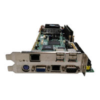
Advantech PCA-6189G2-00A2 User Manual (145 pages)
Full-sized PCI/ISA-bus socket 479 Pentium M/ Celeron M processor-based CPU card
Brand:
Advantech
| Category:
Network Hardware
| Size: 3 MB
Table of Contents
Table of Contents
13
Chapter 1 Hardware Configuration
22
Introduction
22
Features
23
Specifications
23
System
23
Memory
24
Input/Output
24
VGA Interface
24
Ethernet LAN
25
Ultra 160 SCSI
25
Industrial Features
25
Mechanical and Environmental Specifications
25
Jumpers and Connectors
25
Board Layout: Jumper and Connector Location
28
PCA-6189 Block Diagram
30
Safety Precautions
31
Jumper Settings
32
CMOS Clear (J1)
32
How to Set Jumpers
32
Watchdog Timer Output (J2)
32
System Memory
33
CPU FSB and Memory Speed
34
Memory Installation Procedures
34
Processor Installation
34
Chapter 2 Connecting Peripherals
38
Introduction
38
1St & 2Nd (CN1, CN2) IDE Connectors
38
Floppy Drive Connector (CN3)
39
Parallel Port (CN4)
40
USB Ports CN6, CN31, and CN32
41
VGA Connector CN7
42
LVDS Connector VCN2
42
DVI Connector VCN3
43
Ethernet Connector (CN8 and CN34)
43
Serial Ports (COM1 : CN9; COM2 : CN10 )
44
PS/2 Keyboard/Mouse Connector (CN11/CN33)
44
External Keyboard Connector (CN12)
45
CPU Fan Connector (CN14)
45
Front Panel Connectors (CN16, 17, 18, 19, 21&29)
46
Power LED (CN16)
46
External Speaker (CN17)
46
Reset (CN18)
47
Hdd Led (Cn19)
47
ATX Soft Power Switch (CN21)
47
SM Bus Connector (CN29)
47
ATX Feature Connector (CN20)
48
Audio Interface (CN43)
48
Serial ATA Interface (SA0 and SA1)
49
Connecting to SNMP-1000 Remote Manager
49
Auxiliary 4-Pin Power Connector (ATX1)
50
Chapter 3 Award BIOS Setup
52
Introduction
52
CMOS RAM Auto-Backup and Restore
52
Entering Setup
53
Standard CMOS Setup
53
Advanced BIOS Features
54
CPU Features
54
CPU L1 & L2 Cache, CPU L3 Cache
54
Hard Disk Boot Priority
54
Virus Warning
54
Boot Other Device
55
Boot up Floppy Seek
55
Boot up Numlock Status
55
First/Second/Third Boot Device
55
Gate A20 Option
55
Quick Power on Self Test
55
Swap Floppy Drive
55
Typematic Delay (Msec)
55
Typematic Rate (Chars/Sec)
55
Typematic Rate Setting
55
APIC Mode
56
MPS Version Control for os
56
OS Select for DRAM > 64MB
56
Report no FDD for WIN 95
56
Security Option
56
Small Logo(EPA) Show
56
Advanced Chipset Features
57
Active to Precharge Delay
57
CAS Latency Time
57
DRAM Timing Selectable
57
Delay Prior to Thermal
58
Delayed Transaction
58
DRAM Data Integrity Mode
58
DRAM RAS# Precharge
58
DRAM RAS# to CAS# Delay
58
Memory Hole at 15M-16M
58
System BIOS Cacheable
58
Video Bios Cacheable
58
AGP Aperture Size (MB)
59
Boot Display
59
Init Display First
59
On-Chip Frame Buffer Size
59
On-Chip VGA
59
Panel Number
59
Integrated Peripherals
60
On-Chip IDE Device
60
IDE DMA Transfer Access
60
IDE HDD Block Mode
61
On-Chip IDE Device
61
On-Chip Serial ATA
61
Serial ATA Port0/Port1 Mode
61
Onboard Device Menu
61
AC97 Audio
62
On-Board LAN1 Control
62
On-Board LAN2 Control
62
USB 2.0 Controller
62
USB Controller
62
USB Keyboard/Mouse Support
62
Superio Device
62
Auto-Detect PCI CLK
68
Spread Spectrum
68
Exit Without Saving
69
Load Setup Defaults
69
Passwords and Settings
69
Save & Exit Setup
69
Set Supervisor Password
69
Set User Password
69
Before You Begin
72
Features
84
Introduction
84
Installation
85
Win XP Driver Setup (Intel 82541/82551)
85
Introduction
90
SCSI Ids
91
Understanding SCSI
91
Terminating the SCSI Bus
92
Configuring the SCSI Interface with Scsiselect
93
Starting Scsiselect
95
Using SCSI Disk Utilities
99
Installation under Windows 2000
100
Windows 9X Driver Setup Procedure
100
Features
106
Installation
106
Introduction
106
Introduction
108
Windows XP Driver Setup
109
Using the OBS Hardware Doctor Utility
111
Dynamic Video Memory Technology (DVMT)
78
Introduction
78
Windows XP Driver Setup
79
Chapter 4 Chipset Software Install Utility
72
Introduction
72
Windows XP Driver Setup
73
Chapter 5 VGA Setup
78
Chapter 6 LAN Configuration
84
Chapter 7 SCSI Setup & Configuration
90
Chapter 8 USB 2.0 Configuration
106
Chapter 9 Onboard Security Setup
108
Chapter 10 SATA RAID Setup
114
Entering Setup
114
Introduction
114
Array Configuration Utility
115
Managing Arrays
115
Add/Delete Hotspares
116
Adding/Removing a Bootable Array
116
Creating Arrays
116
Initializing Disk Drives
116
Installing the Driver
117
Rebuilding Arrays
117
Appendix A Programming the Watchdog
120
Programming the Watchdog Timer
120
Reset/ Interrupt Selection
120
Watchdog Timer Overview
120
Example Program
123
Appendix B Pin Assignments
130
IDE Hard Drive Connector (CN1, CN2)
130
Floppy Drive Connector (CN3)
131
Parallel Port Connector (CN4)
132
USB Connector (CN6)
133
VGA Connector (CN7)
133
VCN2 LVD Connector
134
COM1/COM2 RS-232 Serial Port (CN9, CN10)
135
VCN3 DVI Connector
135
External Keyboard Connector (CN12)
136
Power LED (CN16)
136
PS/2 Keyboard/Mouse Connector (CN11)
136
External Speaker Connector (CN17)
137
Power LED (CN16)
137
ATX Feature Connector (CN20)
138
Reset Connector (CN18)
138
ATX Feature Connector (CN20)
139
ATX Soft Power Switch (CN21)
139
H/W Monitor Alarm (CN22)
140
SM Bus Connector (CN29)
140
Audio Interface (CN43)
141
LCD Inverter Power Connectore (VP1)
141
System I/O Ports
142
DMA Channel Assignments
143
Interrupt Assignments
143
1St MB Memory Map
144
PCI Bus Map
144
Advertisement
Advertisement
Related Products
Advantech PCA-6189
Advantech PCA-6189VE-00A2
Advantech PCA-6189VG-00A2
Advantech PCA-6189F-00A2
Advantech PCLD-8762
Advantech PCA-6187F-00A2
Advantech PCA-6186
Advantech PCA-6188G2-00A1
Advantech PCA-6186G2-00A1
Advantech PCA-6180F
Advantech Categories
Motherboard
Computer Hardware
Desktop
Touch Panel
Network Router
More Advantech Manuals
Login
Sign In
OR
Sign in with Facebook
Sign in with Google
Upload manual
Upload from disk
Upload from URL