
Related Manuals for Atlanta Attachment Company 1345-6A


Summary of Contents for Atlanta Attachment Company 1345-6A
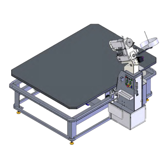
- Page 1 1345-6A model Revision 0 Updated Apr 4, 2012 Technical Manual & Parts Lists Atlanta Attachment Company 362 Industrial Park Drive Lawrenceville, GA 30046 770-963-7369 • www.atlatt.com...
- Page 2 Technical Manual & Parts Lists...
- Page 3 Attachment Company. In addition to any confidentiality and non-disclosure obligations that currently exist between you and Atlanta Attachment Company, your use of these materials serves as an acknowledgment of the confidential and proprietary nature of these materials and your duty not to make any unauthorized use or disclosure of these materials.
-
Page 4: Table Of Contents
Technical Manual & Parts Lists Contents Important Safety Instruction ........................1 Mandatory Information ..........................1 Scope of the Instruction Material ........................ 1 Intended Use ............................... 1 Exclusion of Misuse ............................ 1 Liability ............................... 2 Choice and Qualification of Personnel ....................... 2 Training ............................... - Page 5 Technical Manual & Parts Lists Repair, Electrical............................8 Ventilation/Hazardous Gases ........................8 Hydraulic and Pneumatic Systems ......................8 General Liability ............................9 Starting Machine Movements ........................9 A Word to the End User..........................9 Safety Precautions ............................. 10 Motor Parameter Settings ......................... 11 Instructions for the FP220 with three digit display ...................
- Page 6 Installation..............................51 Adjustments .............................. 51 ASSEMBLY / ADJUSTMENT INSTRUCTIONS .................. 52 Assembly Drawings & Parts Lists ......................54 1345-6A Tape Edge Machine ........................55 13451000 Table Base Assembly ....................... 56 13452500A Table Assembly........................57 134549300A Control Button Panel ......................58 13452000D Column Lift Assembly ......................
- Page 7 Technical Manual & Parts Lists SSIN-300UX6M Sewing Head ......................... 76 13453800 Gear Lock Assembly........................ 77 13453600 Column Assembly ........................78 1345-500 Parts List ........................... 79 1345-6WD1 Wiring Diagram ........................80...
-
Page 8: Important Safety Instruction
Mandatory Information All persons operating and/or working on the 1345-6A Tape Edge Machine should read and understand all parts of the Safety Instructions. This applies, in particular, for persons who only operate and/or work on the unit occasionally (e.g. for maintenance and repair). Persons who have difficulty reading must receive particularly thorough instruction. -
Page 9: Liability
Technical Manual & Parts Lists Liability The machine should only be operated when in perfect working order, with due regard for safety and the potential dangers, as well as in accordance with the Instruction Material. Faults and malfunctions capable of impairing safety should be remedied immediately. We cannot accept any liability for personal injury or property damage due to operator errors or non-compliance with the safety instructions contained in this booklet. -
Page 10: A Word To The Operator
Technical Manual & Parts Lists A Word to the Operator The greatest danger inherent in our machines: is that of fingers, hands or loose clothing being drawn into a machine by live, coasting or rotating tools or assemblies or of being cut by sharp tools or burned by hot elements. LWAYS BE CONSCIOUS OF THESE DANGERS Safety Equipment on the Machines All machines are delivered with safety equipment, which shall not be removed or... -
Page 11: Protective Eyewear
Technical Manual & Parts Lists Protective Eyewear Protective eyewear that has been tested by the local authorities should be worn whenever there is a possibility of loose or flying objects or particles such as when cleaning the machine with compressed air. Tools Always count the number of tools in your possession before starting work on the machine. -
Page 12: Important Notices
Technical Manual & Parts Lists Important Notices Reporting and Fighting Fires Read the instructions posted in the factory with regard to reporting fires and the emergency exits. Make sure you know exactly where the fire extinguishers and sprinkler systems are located and how they are operated. -
Page 13: Delivery Of The Machine/Packaging
Technical Manual & Parts Lists - Kinetic energy - Note that some motors or spindles, for example, may continue to run or coast run on after being switched off. - Potential energy - Individual assemblies may need to be secured if necessary for repair work. Delivery of the Machine/Packaging Note any markings on the packaging, such as weights, lifting points and special information. -
Page 14: Workplace Environment
Technical Manual & Parts Lists Workplace Environment Our machines are designed for use in enclosed rooms: Permissible ambient temperature approx. 5 - 40 °C (40 - 104 °F). Malfunctions of the control systems and uncontrolled machine movements may occur at temperatures outside this range. Protect against climatic influences, such as electrostatic charges, lightning strikes, hail, storm damage, high humidity, salinity of the air in coastal regions. -
Page 15: Repair
Technical Manual & Parts Lists When scrapping (disassembling) the machine and its assemblies, ensure that these materials are disposed of safely. Either commission a specialist company familiar with the local regulations or note the local regulations when disposing of these materials yourself. Materials should be sorted properly. Repair Replacement Parts We cannot accept any liability whatsoever for damage due to the use of parts made by other... -
Page 16: General Liability
Technical Manual & Parts Lists General Liability Liability for machine damage and personal injury is extinguished completely if any unauthorized conversions or modifications are undertaken. The machine must not be modified, enlarged or converted in any way capable of affecting safety without the manufacturer's prior approval. Starting Machine Movements Read the Instruction Manual carefully to establish which keys and functions start machine movements. -
Page 17: Safety Precautions
Technical Manual & Parts Lists Safety Precautions Safety should be a constant concern for everyone. Always be careful when working with this equipment. While normal safety precautions were taken in the design and manufacture of this equipment, there are some potential safety hazards. Everyone involved with the operation and maintenance of this equipment should read and follow the instructions in this manual. -
Page 18: Motor Parameter Settings
Technical Manual & Parts Lists Motor Parameter Settings There are two models of Efka controllers. The older FP220 had a three digit display. The newer AB221 has a four digit display. Depending on the Efka Controller model, different instructions apply. Instructions for the FP220 with three digit display When replacing or installing a new Efka Controller, perform a master reset of the parameters using the following instructions. -
Page 19: Instructions For The Ab221 With Four Digit Display
Technical Manual & Parts Lists Parameter 702 sets the deceleration speed step in RPM / sec which controls the slowdown of the motor independent of how fast the knee pad is pushed in. Min is 1000, max is 9990, default is 9990 (999 displayed). Parameter 703 sets the max normal corner carriage speed in RPM. - Page 20 Technical Manual & Parts Lists Parameter 111 sets the max straight sew head speed in RPM. Min is 200, max is 9900, default is 3000. Parameter 701 sets the acceleration speed step in RPM / sec which limits the speed up of the sew motor independent of how fast the knee pad is let out.
- Page 21 Technical Manual & Parts Lists...
-
Page 22: Servicing The Sew Head
Technical Manual & Parts Lists Servicing the Sew Head Fig. 1 Installation Assemble the oil pan to the hangers. Insert the assembled oil pan into the machine cut-out table placing four rubber bushings in the hanger holes as shown in Fig. 1. Attach the oil drain jar to the oil pan as shown in Fig. -
Page 23: Lubrication
Technical Manual & Parts Lists Lubrication Machines of Class 300U have a semi-automatic lubricating system comprising of a hollow arm shaft and a hollow bed shaft which act as oil reservoirs. The oil is distributed to all of the principal bearings by centrifugal force through small jets in the shafts when the machine is in operation. -
Page 24: Setting The Needle
Technical Manual & Parts Lists Setting the Needle Refer to Fig. 6. Turn the machine pulley over toward the operator until the needle bar is at its highest point. Loosen the needle set screw. Insert the needle into the needle bar and clamp as far as it will go making certain that the scarf of the needle faces toward the left. -
Page 25: Threading The Machine
Technical Manual & Parts Lists Threading the Machine Either left twist or right twist thread may be used in the needles and loopers. Rough or uneven thread or thread which passes through the needle eye with difficulty will interfere with successful operation of the machine. -
Page 26: Threading The Loopers
Technical Manual & Parts Lists Threading the Loopers Pass the thread from the unwinder through the threading points as indicated. Draw approximately two inches of thread through the looper eye with which to start sewing. Tension Tension on the thread should be as light as possible while still Fig. -
Page 27: Alternating Presser With Pneumatic Pressure Control
Technical Manual & Parts Lists Alternating Presser with Pneumatic Pressure Control Adjust the height of the Pressure Cylinder with the presser feet resting on the throat plate. There should be a clearance of 1/4” between the Presser Bar Spring Fork and bottom of the cylinder. -
Page 28: Machine With Puller Feed
Technical Manual & Parts Lists Machine with Puller Feed The length of the stitch is determined by the stitch gears in the puller feed mechanism. The compound feed stitch length should be set slightly shorter than the stitch length of the puller feed. -
Page 29: Machines With Alternating Pressers
Technical Manual & Parts Lists Machines with Alternating Pressers The lift of the vibrating and lifting pressers is controlled by an adjustable eccentric. To adjust, remove the arm cover at the rear of the machine. Turn the machine pulley over toward the operator until the feeding presser is down. -
Page 30: Setting The Height Of Feed Bar
Technical Manual & Parts Lists Setting the Height of Feed Bar When the feed bar is set at the correct height, the feed lift link clamp will be aligned with the rock shaft timing flat. To adjust, make certain that the feed lifting crank timing screw, Fig. -
Page 31: Timing The Feed Lift Eccentric
Technical Manual & Parts Lists Timing the Feed Lift Eccentric When the feed dog is at its highest position, the top of the teeth should be parallel with, and project full depth of the teeth above the upper surface of the throat plate. To adjust, insert screwdriver in the hole in the feed strap and loosen the two set screws, Fig. -
Page 32: Setting The Distance From The Looper To The Needle
Technical Manual & Parts Lists Setting the Distance from the Looper to the Needle Sidewise Setting When the looper is correctly positioned, the point of the looper just clears the scarf of the needle on the forward stroke of the looper. To adjust, turn the machine pulley until the looper point is directly opposite of the center of the needle. -
Page 33: Timing Looper Driving Crank
Technical Manual & Parts Lists Timing Looper Driving Crank When the looper driving crank is properly timed, the point of the looper will pass above the eye of the needle at the same distance on both the forward and backward strokes of the looper. To adjust when the point of the looper passes higher on the forward stroke, loosen the looper driving crank set screw, Fig. -
Page 34: Positioning Spreader
Technical Manual & Parts Lists Positioning Spreader Fig 31 Fig 32 Sidewise and Height Setting When the looper on its forward stroke is passing the spreader a) The point of the spreader should be exactly opposite the top of the thread groove at the left side of the looper. -
Page 35: Adjusting Needle Thread Take-Up
Technical Manual & Parts Lists Adjusting Needle Thread Take-Up Fig 34 The needle thread take-up and thread guide may be adjusted to increase or decrease the amount of thread drawn at the top of the needle bar stroke. To increase the amount, loosen the thread take-up screw, Fig. - Page 36 Technical Manual & Parts Lists...
-
Page 37: Singer® 300Ux6 Assembly Drawings & Parts Lists
Technical Manual & Parts Lists Singer® 300UX6 Assembly Drawings & Parts Lists Atlanta Attachment Company is the exclusive stocking distributor for Singer Tape Edge Sewing Heads and recommended spare parts for Singer Tape Edge machines. We can also supply proprietary parts in most cases for Cash*, Spuhl*, Porter, United* Tape Edge workstations. - Page 38 Technical Manual & Parts Lists...
-
Page 39: Upper Shaft Assembly
Technical Manual & Parts Lists Upper Shaft Assembly NO. QTY PART # DESCRIPTION QTY PART # DESCRIPTION 415138 Needle Bar Crank 268065 Eccentric Adjusting Disc 32848 Arm Shaft Ball Bearing 268618 Disc Spring 281239 Needle Bar Crank 415076 Eccentric Flange 549024 Crank Position Screw 415077... - Page 40 Technical Manual & Parts Lists...
-
Page 41: Front Assembly Sewing Arm
Technical Manual & Parts Lists Front Assembly Sewing Arm PART # DESCRIPTION NO. QTY PART # DESCRIPTION 414545 Thread Guide Set Screw 267617 Hinge Pin 268258 Oil Wick 267657 Presser Bar 267627 Lifting Link 267658 Hinge Stud 415061 Lifting Crank 281912 Needle Bar 141338... - Page 42 Technical Manual & Parts Lists...
-
Page 43: External Parts Sewing Arm
Technical Manual & Parts Lists External Parts Sewing Arm NO. QTY PART # DESCRIPTION NO. QTY PART # DESCRIPTION 32789 Lifting Rock Shaft 414528 Set Screw 32788 Shaft Crank 268149 Stud Sleeve 267633 Lifting Rock Shaft 214529 Stud Spring 548035 Crank Pin 268148 Regulating Stud... - Page 44 Technical Manual & Parts Lists...
-
Page 45: Lower Shaft Assembly
Technical Manual & Parts Lists Lower Shaft Assembly PART # DESCRIPTION PART # DESCRIPTION 415176 Driving Crank 541197 Hinge Stud Nut 347099 Position Screw 545297 Cap Screw 500264-833 Set Screw 415082 Eccentric 268102 Hole Cover 415073 Eccentric Flange 414563 Screw 415074 Eccentric Flange 204925... - Page 46 Technical Manual & Parts Lists...
-
Page 47: Front Assembly Sewing Bed
Technical Manual & Parts Lists Front Assembly Sewing Bed PART # DESCRIPTION NO. QTY PART # DESCRIPTION 559061 Feed Dog 281208 Needle Guard 267665 Loop Deflector 268380 Looper Deflector Screw 281207 Needle Guard 559064 Feed Dog Shank 141478 Set Screw 414559 Adjusting Screw 141494... - Page 48 Technical Manual & Parts Lists...
-
Page 49: Cross Shaft In Sewing Bed
Technical Manual & Parts Lists Cross Shaft in Sewing Bed NO. QTY PART # DESCRIPTION NO. QTY PART # DESCRIPTION 281975 Spreader 415194 Crank 268162 Spreader Point 544204-001 Set Screw 414552 Spreader Screw 414575 Screw Stud 547670 Washer 32825 Oil Wick 415196 Spreader Holder 545424... - Page 50 Technical Manual & Parts Lists...
-
Page 51: External Parts Sewing Arm
Technical Manual & Parts Lists External Parts Sewing Arm PART # DESCRIPTION PART # DESCRIPTION 281929 Foot Lifter Lever 267714 Housing Support 201363 Hinge Screw 414567 Hinge screw 267707 Tension Releasing Plate 548154 Washer 543850-001 Releasing Plate Pin 545405 414577 Hinge Screw 267738 Spring Arm... - Page 52 Technical Manual & Parts Lists...
-
Page 53: External Parts Sewing Arm
Technical Manual & Parts Lists External Parts Sewing Arm PART # DESCRIPTION NO. QTY PART # DESCRIPTION 268506 Thread Guide Bracket 54279 Thread Guide 268111 Thread Guide Bracket 226206 Releasing Pin 268505 Thread Guide 415357 Tension Releaser 50169 Screw 543853-003 Spacing Collar 414537 Screw... - Page 54 Technical Manual & Parts Lists...
-
Page 55: External Parts Sewing Arm
Technical Manual & Parts Lists External Parts Sewing Arm NO. QTY PART # DESCRIPTION NO. QTY PART # DESCRIPTION 559029 Face Plate 267701-451 Arm Side Cover 268330 Hinge Stud 545295 Screw 545174-452 Set Screw 267656-452 Thread Lubricator 268033 Lock Stud 504019 Screw 228661... - Page 56 Technical Manual & Parts Lists...
-
Page 57: External Parts Sewing Arm
Technical Manual & Parts Lists External Parts Sewing Arm NO. QTY PART # DESCRIPTION NO. QTY PART # DESCRIPTION 559037 Bed Plate (Right) 1 559073 Looper Cover Thumb Screw 414508 Screw 1 415294 Thread Tension 559035 Bed Plate (Left) 1 415291 Thread Tension Stud 559060 Throat Plate... -
Page 58: Installation Of Footlift Link & Handle
Technical Manual & Parts Lists Installation of Footlift Link & Handle Handle diagram is in the assemblies Tools Required (1) 7/16” wrench (1) 7mm wrench (1) 8mm wrench (1) 9mm wrench (1) 7/64” allen wrench (1) 1/8” allen wrench Installation If not already installed, mount the pivot bracket (1345-503) to the sewing head as shown using the 1/4-20 bolts and washers provided. -
Page 59: Assembly / Adjustment Instructions
Technical Manual & Parts Lists ASSEMBLY / ADJUSTMENT INSTRUCTIONS 1. Position the column assy (item A) with the lower edge below the bottom of the slide support bracket (item B). DO NOT ADJUST WITHT THE COLUMN OR TABLE IN THE "UP"... - Page 60 Technical Manual & Parts Lists...
-
Page 61: Assembly Drawings & Parts Lists
Company. In addition to any confidentiality and non-disclosure obligations that currently exist between you and Atlanta Attachment Company, your use of these materials serves as an acknowledgment of the confidential and proprietary nature of these materials and your duty not to make any unauthorized use or... -
Page 62: 1345-6A Tape Edge Machine
Technical Manual & Parts Lists 1345-6A Tape Edge Machine AAC Drawing Number 9001651 Rev 2 PART # DESCRIPTION 1345-6WD1 DIAGRAM, WIRING 13452500A TABLE ASSY, COMPLETE 13453420A BEARING STUD,INNER 13453428 MOUNT, CAM FOLLOWER 13453646 TAPE MOUNT, PULLEY 134563000A CARRIAGE ASSEMBLY 1345LAB2... -
Page 63: 13451000 Table Base Assembly
Technical Manual & Parts Lists 13451000 Table Base Assembly AAC Drawing Number 9001365 Rev 7 PART # DESCRIPTION 0411-1063 ROD, THREADED, 5/8-11 X 5 1345027 FRAME, WELDMENT TAPE EDGE 13451019 GEAR RACK, SHORT 13451020 GEAR RACK, LONG 13451021 GEAR RACK, CORNER 13451029 PAD, RUBBER 13459500... -
Page 64: 13452500A Table Assembly
Technical Manual & Parts Lists 13452500A Table Assembly AAC Drawing Number 9001366 Rev 11 PART # DESCRIPTION 13451000 BASE ASSY LIFT TABLE TAPE 13451200 TABLE TOP ASSY,QUEEN 13452000D COLUMN, LIFT ASSY 13452027 LINK, CABLE ASSY,TWIN BBTRA613 WASHER,THRUST,STL, .375B NNJ5/16-18 NUT,JAM,5/16-18 PPP2217 WIRE CLAMP, .337I.D. -
Page 65: 134549300A Control Button Panel
Technical Manual & Parts Lists 134549300A Control Button Panel AAC Drawing Number 9001503 Rev 3 PART # DESCRIPTION AR 13454LAB LABEL, SWITCH PANEL 13459008A CABLE, POT, IK, 4 FT. 13459301D PANEL,CONTORL BUTTON,2 PO EE15Y PLATE, LEGEND, YELLOW EE3X01 BLOCK,P.B. CONTACT, N.C. EE3X10 BLOCK,P.B. - Page 66 Technical Manual & Parts Lists...
-
Page 67: 13452000D Column Lift Assembly
Technical Manual & Parts Lists 13452000D Column Lift Assembly AAC Drawing Number 9002809 Rev 1 PART # DESCRIPTION 1345093 BKT,EDGE GUIDE 1345130 TOP MOD.,SLIP RING 1345131 PLATE,SLIDE, ADJ 1345132 BAR, BRACE,.25 THK 1345134 NUT PLATE 1345135 PLATE, SLIDE 1345136 BKT,LOWER GIB STOP 13452004A PIN, COLUMN 13452006B... - Page 68 Technical Manual & Parts Lists...
-
Page 69: 13459500 Control Box
Technical Manual & Parts Lists 13459500 Control Box AAC Drawing Number 9001947 Rev 1 PART # DESCRIPTION 13459004A MOUNTING BRACKET, CAPACIT 13459501 HIGH VOLTAGE PANEL 13459503 COVER, ELECTRICAL PANEL 40-322 BOTTOM, AC POWER LOCKOUT 40-323 TOP, AC POWER LOCKOUT EEAK42BS RIVET,BLIND 1/8 DIA ALUM. - Page 70 Technical Manual & Parts Lists...
-
Page 71: 134563000A Carriage Assembly
Technical Manual & Parts Lists 134563000A Carriage Assembly AAC Drawing Number 9001652 Rev 2 PART # DESCRIPTION AR 1345-6WD1 DIAGRAM, WIRING 1345051 COVER,CARRIAGE,FRONT 13453003A COVER,CARRIAGE, RIGHT 13453037 SPACER, 7/16 OD X 9/32 ID 13453060C DOOR, CARRIAGE, RH 13453061A DOOR CARRIAGE, REAR 13453062A COVER,CARRIAGE LH 13453303... - Page 72 Technical Manual & Parts Lists...
-
Page 73: 134543300A Top Carriage Assembly
Technical Manual & Parts Lists 134543300A Top Carriage Assembly AAC Drawing Number 9001526 Rev 12 PART # DESCRIPTION PART # DESCRIPTION 0211-209 PLATE,NUT,10-32@2.25 CTC FF3234 STRAIN RELIEF,LIQ TIGHT 029-003A PLATE, NUT, 1/4-20 @ 1.50 FF8465 NUT,LOCK,3/4NPT,NYLON,BLK 1278-7055D PROX SWITCH W/PLUG,12" FFSM312LV BANNER MINI-BEAM w/OUT PL 1345-505... - Page 74 Technical Manual & Parts Lists...
-
Page 75: 1345100 Knee Switch Assembly
Technical Manual & Parts Lists 1345100 Knee Switch Assembly AAC Drawing Number 1345100 Rev 5 PART # DESCRIPTION 1345101 PLATE,TRANSDUCER END 1345102 MOUNT, TRANSDUCER 1345103 PLATE,SPRING,TRANSDUCER 1345104 CLAMP,TRANSDUCER 13453306 BLOCK,RAIL STOP 13453309 RAIL BKT ASBLY 13453337 BRACKET,RAIL SUPPORT 13453361 BRKT, SPRING TENSION FF002304A LINEAR TRANSDUCER ASBY MM9540K53... - Page 76 Technical Manual & Parts Lists...
-
Page 77: 13453400A Carriage Guide Assembly
Technical Manual & Parts Lists 13453400A Carriage Guide Assembly AAC Drawing Number 9001193 Rev 6 PART # DESCRIPTION 13453401A CARRIAGE GUIDE FRAME ASSY 13453404 ROLLER YOKE ASSY 13453408 GUIDE ARM ASSY. 13453411 STUD, ROLLER BEARING 13453413 ROLLER, GUIDE 13453414 HUB, ROLLER GUIDE 13453415 PLATE, CABLE HOLDER 13453416... - Page 78 Technical Manual & Parts Lists...
-
Page 79: 134549000B Control Box Assembly
Technical Manual & Parts Lists 134549000B Control Box Assembly AAC Drawing Number 9001516 Rev 1 PART # DESCRIPTION 13459001B SUB PANEL, CARRIAGE -3&4B 13459004A MOUNTING BRACKET, CAPACIT 13459006 JUNCTION BOX ASSY AR 1345LAB1 LABEL AAF3/16 CLAMP, BLACK PLASTIC FF1N4937 DIODE,FAST 200NS,1A FF264-341 TERMBLK,WAGO,TOP,DUAL,GRY FF264-347... - Page 80 Technical Manual & Parts Lists...
-
Page 81: 134553500D Gear Box Assembly
Technical Manual & Parts Lists 134553500D Gear Box Assembly AAC Drawing Number 9002524 Rev 3 PART # DESCRIPTION 0211-209 PLATE,NUT,10-32@2.25 CTC 132556-258 KEY, 3/16 X .813 L 1345043 BRKT, GEAR BOX, LOWER 1345046 SPACER, GEARBOX MOUNT 1345048 PLATE, MOUNTING, GEARBOX 1345049 SHIM. - Page 82 Technical Manual & Parts Lists...
-
Page 83: Ssin-300Ux6M Sewing Head
Technical Manual & Parts Lists SSIN-300UX6M Sewing Head AAC Drawing Number 9002945 Rev 3 PART # DESCRIPTION 1278-7055D PROX SWITCH W/PLUG,12" 1345-004 BLOCK, STOP FOR BINDER 1345-009A SPACER,1/8X1X1.8L 1345-009B SLEEVE,.25D X.19ID X .5L 1345-025 TAPE ROLL HOLDER ASSY 1345-505 BLOCK, FOOT UP SENSOR 268382 LOOPER 13453608... -
Page 84: 13453800 Gear Lock Assembly
Technical Manual & Parts Lists 13453800 Gear Lock Assembly AAC Drawing Number 9001130 Rev 1 PART # DESCRIPTION 13453801 SUPPORT GEAR LOCK ASSY. IIS012X096 SPRING PIN, 3/16X1.5 MM61095K53 KNOB, BALL,3/8-16 TAP RRLC0742HJ SPRING, COMP. .072X.66X3 13453804 MANDREL,GEAR LOCK... -
Page 85: 13453600 Column Assembly
Technical Manual & Parts Lists 13453600 Column Assembly AAC Drawing Number 9001525 Rev 2 PART # DESCRIPTION 13453604 PIVOT, SUPPORT, ACTUATOR 13453614 CLEVIS, ACTUATOR 13453615 COLUMN,SEWING HEAD 13453620 ACTUATOR,BRKT,COLUMN 13453622 PIVOT,SUPPORT, ACTUATOR MM85151-10M1 ACTUATOR,MOD MM98330A245 CLEVIS PIN 2.25LG STL MM98335A064 SPRING CLIP MMAGH25CAN LINEAR BEARING... -
Page 86: 1345-500 Parts List
Technical Manual & Parts Lists 1345-500 Parts List AAC Drawing Number 192500B Rev 7 PART # DESCRIPTION 1349518 Foot Lift Lever 1345-503 Pivot Bracket 1345077 Stop Clamp 1345-504 Pivot Arm MMBTH-2 Handle SSSC98048 Screw, Socket Cap AR 1345-500INS Instructions... -
Page 87: 1345-6Wd1 Wiring Diagram
Technical Manual & Parts Lists 1345-6WD1 Wiring Diagram... - Page 88 Atlanta Attachment Company (AAC) Statement of Warranty Manufactured Products Atlanta Attachment Company warrants manufactured products to be free from defects in material and workmanship for a period of eight hundred (800) hours of operation or one hundred (100) days whichever comes first. Atlanta Attachment Company warrants all electrical components of the Serial Bus System to be free from defects in material or workmanship for a period of thirty six (36) months.
- Page 89 Declaración de Garantia Productos Manufacturados Atlanta Attachment Company garantiza que los productos de fabricación son libres de defectos de mate-rial y de mano de obra durante un periodo de ochocientos (800) horas de operación o cien (100) días cual llegue primero.
- Page 90 Atlanta Attachment Company 362 Industrial Park Drive Lawrenceville, GA 30046 770-963-7369 www.atlatt.com Printed in the USA...
Need help?
Do you have a question about the 1345-6A and is the answer not in the manual?
Questions and answers