
Related Manuals for Atlanta Attachment Company 1347D


Summary of Contents for Atlanta Attachment Company 1347D
- Page 1 1347D Model Revision 9.1 Updated Sept 6, 2012 Technical Manual & Parts Lists Atlanta Attachment Company 362 Industrial Park Drive Lawrenceville, GA 30046 770-963-7369 • www.atlatt.com...
- Page 3 Attachment Company. In addition to any confidentiality and non-disclosure obligations that currently exist between you and Atlanta Attachment Company, your use of these materials serves as an acknowledgment of the confidential and proprietary nature of these materials and your duty not to make any unauthorized use or disclosure of these materials.
-
Page 4: Table Of Contents
Airline Connections ..........................17 Lubrication ..............................17 Parts Replacement ............................. 17 Clutch Parts List ............................19 1347D Puller Motor Parameter List ......................20 1347D Sewing Head Parameter List ......................21 Electric Eye Sensor Adjustment ....................... 22 Reflective Tape Maintenance ........................22 Recommended Spare Parts List ........................ - Page 5 1347127 Head Mount Assembly ......................46 1961-900C Control Box Assembly ......................48 1961-300EB Worm Gear Puller Assembly, 18” ..................50 1961-250F Prefeed Assembly ........................52 33008708 Ball Bearing Disc Assembly ....................53 1347D-PD Pneumatic Diagram ........................ 55 1347D-WD Control Wiring Diagram ....................... 56...
-
Page 6: Important Safety Instruction
Mandatory Information All persons operating and/or working on the 1347D should read and understand all parts of the Safety Instructions. This applies, in particular, for persons who only operate and/or work on the unit occasionally (e.g. for maintenance and repair). Persons who have difficulty reading must receive particularly thorough instruction. -
Page 7: Liability
Technical Manual & Parts Lists Liability The machine should only be operated when in perfect working order, with due regard for safety and the potential dangers, as well as in accordance with the Instruction Material. Faults and malfunctions capable of impairing safety should be remedied immediately. We cannot accept any liability for personal injury or property damage due to operator errors or non-compliance with the safety instructions contained in this booklet. -
Page 8: Safety Equipment On The Machines
Technical Manual & Parts Lists A Word to the Operator The greatest danger inherent in our machines: is that of fingers, hands or loose clothing being drawn into a machine by live, coasting or rotating tools or assemblies or of being cut by sharp tools or burned by hot elements. LWAYS BE CONSCIOUS OF THESE DANGERS Safety Equipment on the Machines All machines are delivered with safety equipment, which shall not be removed or... -
Page 9: Protective Eyewear
Technical Manual & Parts Lists Protective Eyewear Protective eyewear that has been tested by the local authorities should be worn whenever there is a possibility of loose or flying objects or particles such as when cleaning the machine with compressed air. Tools Always count the number of tools in your possession before starting work on the machine. -
Page 10: Important Notices
Technical Manual & Parts Lists Important Notices Reporting and Fighting Fires Read the instructions posted in the factory with regard to reporting fires and the emergency exits. Make sure you know exactly where the fire extinguishers and sprinkler systems are located and how they are operated. - Page 11 Technical Manual & Parts Lists - Kinetic energy - Note that some motors or spindles, for example, may continue to run or coast run on after being switched off. - Potential energy - Individual assemblies may need to be secured if necessary for repair work. Delivery of the Machine/Packaging Note any markings on the packaging, such as weights, lifting points and special information.
-
Page 12: Maintenance
Technical Manual & Parts Lists Protect against influences from the surroundings: no structure-borne vibrations, no grinding dust, or chemical vapors. Protect against unauthorized access. Ensure that the machine and accessories are set up in a stable position. Ensure easy access for operation and maintenance (Instruction Manual and layout diagram); also verify that the floor is strong enough to carry the weight of the machine. -
Page 13: Repair
Technical Manual & Parts Lists Repair Replacement Parts We cannot accept any liability whatsoever for damage due to the use of parts made by other manufacturers or due to unqualified repair or modification of the machine. Repair, Electrical The power supply must be switched off (master switch off) and secured so that it cannot be switched on again inadvertently before starting any work on live parts. -
Page 14: A Word To The End User
Technical Manual & Parts Lists A Word to the End User The end user has sole responsibility to enforce the use of safety procedures and guards on the machine. Any other safety devices or procedures due to local regulations should be should be retrofitted in accordance to these regulations and/or the EC Directive on the safety of machines. -
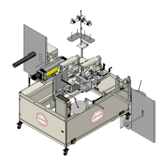
Page 15: Features
Technical Manual & Parts Lists The 1347D is an automatic workstation for hemming and/or binding one or both sides of a mattress border or other flat goods. The material may be on rolls or festooned. Features Dual adjustable single needle chain-stitch sewing heads ... -
Page 16: Operating Procedure
Technical Manual & Parts Lists Operating Procedure 1. Press the green button on the circuit breaker on the back of the control box. Leave this on except when locking out the power for maintenance. 2. Press the On/Start button momentarily to power up the machine. The amber Sensor light should light. -
Page 17: Controls And Adjustments
Technical Manual & Parts Lists Controls and Adjustments Front of Control Box 1. Emergency Stop button- Pressing this button will turn off power to the machine. This button locks in and off when pressed. Twist to release; the machine will not start with this button in. -
Page 18: Manual Sew Pedals
Technical Manual & Parts Lists Manual Sew Pedals Two manual sew pedals are located on the front of the frame. They operate both of the sewing heads at a slower speed than automatic speed. They are used for maintenance and for loading the machine. Folder/Head Adjustment The folders are mounted on the sewing head slides and move with the heads. -
Page 19: Front Roll Holder
Technical Manual & Parts Lists Front Roll Holder The front roll holder has a material out sensor mounted behind the disc. This sensor can be adjusted up or down to set the amount of material left on the rod when the machine stops. There should be enough material left to make a splice when the next roll is loaded. -
Page 20: Thread Sensor Instructions
Technical Manual & Parts Lists Thread Sensor Instructions... -
Page 21: Clutch-Brake Installation & Maintenance
Technical Manual & Parts Lists Clutch-Brake Installation & Maintenance Installation Sheave and Pilot Mounting (See Figure 1) 1. Insert the Key (Item 21) into the keyway of the mounting shaft. 2. Slide the BW Clutch onto the mounting shaft until the Key (Item 21) is seated in the BW Clutch. -
Page 22: Airline Connections
Technical Manual & Parts Lists Airline Connections A 1/8 NPT female air inlet fitting is provided in the piston (Item 13) for the airline connection. The Air Hose Assembly (Item 19) must be used so that no side forces are introduced to the air chamber-piston assembly. - Page 23 Technical Manual & Parts Lists 20.Coat the new O-ring Seals (Items 10 and 11) with fresh O-ring Lubricant. 21.Install the new O-ring Seals (Items 10 and 11). 22.Slide the Piston (Item 13) into the Air Chamber (Item 9). 23.Slide the Air Chamber and Piston onto the Hub (Item 1). 24.Install the new Disc Key (Item 6) into the Hub.
-
Page 24: Clutch Parts List
Technical Manual & Parts Lists Clutch Parts List ITEM DESCRIPTION Retaining Ring (Ext.) Bearing Sheave 5¹ Return Spring 6¹ Disc Key 7¹ Friction Disc Assembly 8¹ Thrust Bearing Air Chamber 10¹ O-Ring Seal (Large) 11¹ O-Ring Seal (Small) Piston Washer Pilot Disc Mount Air Inlet Fitting Air Hose Assembly (Not Shown) -
Page 25: 1347D Puller Motor Parameter List
Technical Manual & Parts Lists 1347D Puller Motor Parameter List SUGGESTED/ SHIPPED/ PARAMETER RANGE 11347D PARAMETER DESCRIPTION (PULLER MOTOR) VALUE VALUE Do this first ***** **** Perform a master reset before programming, see below Mode (Lockstitch) of operation. MUST SET THIS PARAMETER FIRST! F-026=0 to disable the EB401 selection after power on. -
Page 26: 1347D Sewing Head Parameter List
Technical Manual & Parts Lists 1347D Sewing Head Parameter List SUGGESTED/ SHIPPED/ PARAMETER RANGE 11347D PARAMETER DESCRIPTION (SEWING HEADS) VALUE VALUE Do this first ***** **** Perform a master reset before programming, see below Mode (Chainstitch) of operation. MUST SET THIS PARAMETER FIRST! F-026=0 to disable the EB401 selection after power on. -
Page 27: Electric Eye Sensor Adjustment
Technical Manual & Parts Lists Electric Eye Sensor Adjustment To adjust the sensor, first remove the clear plastic cover from the end of the sensor. There are two adjusting screws under the cover. One is labeled “GAIN” and is used to set the sensitivity of the sensor. - Page 28 Technical Manual & Parts Lists...
-
Page 29: Assembly Drawings & Parts Lists
Company. In addition to any confidentiality and non-disclosure obligations that currently exist between you and Atlanta Attachment Company, your use of these materials serves as an acknowledgment of the confidential and proprietary nature of these materials and your duty not to make any unauthorized use or... - Page 30 Technical Manual & Parts Lists...
-
Page 31: 11347D Faux Pillowtop Border Workstation
1347110 MAIN FRAME ASSEMBLY Page 44 1347123 MOUNT, GUIDE 1347125 GUIDE ASSEMBLY 1347128 MOUNT, SCALE 1347129 POINTER *AR 1347D-HPAR PARAMETER LIST,SEWING HD Page 21 *AR 1347D-LAB LABEL SHEET *AR 1347D-PD DIAGRAM,PNEUMATIC Page 55 *AR 1347D-PPAR PARAMETER LIST,PULLER MTR Page 20... -
Page 32: 1347010 Sew Head Assembly
Technical Manual & Parts Lists 1347010 Sew Head Assembly AAC Drawing Number 1347010 Rev 5 NO. QTY PART # DESCRIPTION NO. QTY PART # DESCRIPTION 1278-6364 DISC, TAPE MOUNTING CCCL5F CLAMP COLLAR,5/16" BORE 1347001 SEWING HEAD, MODIFIED D8229555E00 ISOLATOR, FRONT OIL PAN 1347011 OIL PAN, MODIFIED NNH1/4-20... -
Page 33: 1347030 Swing Out Binder Assembly
Technical Manual & Parts Lists 1347030 Swing Out Binder Assembly AAC Drawing Number 1347030 Rev 3 NO. QTY PART # DESCRIPTION NO. QTY PART # DESCRIPTION 1335M-5001 PLATE,MOUNTING SSBC98024 10-32 X 3/8 BUTTON CAP SC 1347022 GUIDE CLAMP SSBC98040 10-32 X 5/8 BUTTON CAP SC 1347039 EDGE GUIDE, BINDER SSM200246... -
Page 34: 1347040 Swing Out Binder Assembly
Technical Manual & Parts Lists 1347040 Swing Out Binder Assembly AAC Drawing Number 1347040 Rev 3 NO. QTY PART # DESCRIPTION NO. QTY PART # DESCRIPTION 1347017 PLATE, MOUNTING WWF6 DO NOT USE - SEE WWFS6 1347022 GUIDE CLAMP SSSC85016 6-40 X 1/4 SOC CAP SC 1347039 EDGE GUIDE, BINDER... -
Page 35: 1347126 Motor / Tensioner Assembly
Technical Manual & Parts Lists 1347126 Motor / Tensioner Assembly AAC Drawing Number 1347126 Rev 0 QTY PART # DESCRIPTION 1347008 BRKT,MOTOR MOUNT 1347046 PLATE,NUT,10-32@1.25 CTC 4059-DC1500A MOTOR & CONTROLLER ONLY MMFS0127 TENSIONER,V-BELT NNH3/8-16 NUT,HEX,3/8-16 NNJ1/4-28 NUT, HEX, JAM, 1/4-28 PP65X1-14 PULLEY,V-BELT 65MM OD SSHC25144... - Page 36 Technical Manual & Parts Lists...
-
Page 37: 1347065 Right Side Folder Assembly
Technical Manual & Parts Lists 1347065 Right Side Folder Assembly AAC Drawing Number 1347065 Rev 4 QTY PART # DESCRIPTION 1136227 HOLDER, ROD, 3/8" DIA., S 1278-3140D NUT PLATE, 10-32, 2 PL 1335-316 ROD, SS, "L", 3/8, 4.0 X 1347062 BASE, FOLDER MOUNT 1347067 MOUNT, FOLDER... - Page 38 Technical Manual & Parts Lists...
-
Page 39: 1347079 Left Side Folder Assembly
Technical Manual & Parts Lists 1347079 Left Side Folder Assembly AAC Drawing Number 1347079 Rev 6 QTY PART # DESCRIPTION 1278-3140D NUT PLATE, 10-32, 2 PL 1347062 BASE, FOLDER MOUNT 1347068 SUPPORT, HOLD DOWN 1347078 CLOTH DOLD DOWN, LS 1347179 MOUNT, FOLDER, LEFT 1347230 FOLDER ASSEMBLY, LS... - Page 40 Technical Manual & Parts Lists...
-
Page 41: 1347080 Binding Roll Support
Technical Manual & Parts Lists 1347080 Binding Roll Support AAC Drawing Number 1347080 Rev 1 QTY PART # DESCRIPTION 1347036 SENSOR BRACKET 1347050 MOUNT, TAPE SPOOL 1347116 RING,TAPE GUIDE 1347117 ROD, BENT, 90 DEG 1981-607 ROD, STRAIGHT, CRS 28201 CROSS BLOCK, LARGE 785-A9-12B STATIONARY CRS DISC WITH FFRK44T-4... - Page 42 Technical Manual & Parts Lists...
-
Page 43: 1347090 Binding Roll Support
Technical Manual & Parts Lists 1347090 Binding Roll Support AAC Drawing Number 1347090 Rev 1 QTY PART # DESCRIPTION 1347036 SENSOR BRACKET 1347050 MOUNT, TAPE SPOOL 1347116 RING,TAPE GUIDE 1347117 ROD, BENT, 90 DEG 1981-607 ROD, STRAIGHT, CRS 28201 CROSS BLOCK, LARGE 785-A9-12B STATIONARY CRS DISC WITH FFRK44T-4... - Page 44 Technical Manual & Parts Lists...
-
Page 45: 1347094 Upper Tension Assembly
Technical Manual & Parts Lists 1347094 Upper Tension Assembly AAC Drawing Number 1347094 Rev 1 QTY PART # DESCRIPTION 1347093 SUPPORT, TENSIONER 1347097 SUPPORT, TENSIONER 1961-211 PLATE, EDGE GUIDE 1961-252D ROD, ROLL, 27" L 1962-3201 CLAMP, 3/4 ROD, 3" CTC TTH32416 HANDLE,THRD,1/4-20X1-1/8 TTH32425... - Page 46 Technical Manual & Parts Lists...
-
Page 47: 1347098 Rewind Assembly W/ Sleeve
Technical Manual & Parts Lists 1347098 Rewind Assembly w/ Sleeve AAC Drawing Number 1347098 Rev 1 NO. QTY PART # DESCRIPTION NO. QTY PART # DESCRIPTION 1334326 MOUNT, FLANGE NNH1/2-13 NUT,HEX,1/2-13 1334376 PLATE, REWIND,24 X 40 NNH3/8-16 NUT,HEX,3/8-16 1334387 CATCH, MATL. TAKEUP REEL NNK1/4-20 KEP NUT, 1/4-20 1334388... - Page 48 Technical Manual & Parts Lists...
-
Page 49: 1347110 Main Frame Assembly
Technical Manual & Parts Lists 1347110 Main Frame Assembly AAC Drawing Number 1347110 Rev 6 NO. QTY PART # DESCRIPTION NO. QTY PART # DESCRIPTION 0411-069B BRKT, THREAD BREAK DETECT EEDC1LG DUCT,WIRE COVER,1" 0411-070 CLAMP, SENSOR BRACKET EEDF1X2 DUCT,WIRE,1X2 1278-6161 FOOT SWITCH MODIFICATION EEDF2X2 DUCT,WIRE,2X2, MOD... - Page 50 Technical Manual & Parts Lists...
-
Page 51: 1347127 Head Mount Assembly
Technical Manual & Parts Lists 1347127 Head Mount Assembly AAC Drawing Number 1347127 Rev 0 QTY PART # DESCRIPTION 1347002 MOUNT, HINGE 1347003 MOUNT, ISOLATOR 1347005 HEAD MOUNT TOP PLATE 1347006 STANDOFF, CLOTH PLATE 1347007 PLATE, HEAD MOUNT 1347009 SUPPORT, OILPAN 1347045 BLOCK, INDEX 1347047... - Page 52 Technical Manual & Parts Lists...
-
Page 53: 1961-900C Control Box Assembly
Block, N.C. 1 0211-705H Cable 3 EE3X10 Block, N.O. 1 4059-EXT1 Cable 3 EEA3L Button Latch 1 4059-EXT2 Cable 1 EECA491024 Mini Contactor 1 1961-909A Cable 1 EEPF3 Green Button 63 AR 1347D-WD Wiring Diagram Page 56 1 EEPF4 Red Button... - Page 54 Technical Manual & Parts Lists...
-
Page 55: 1961-300Eb Worm Gear Puller Assembly, 18
Technical Manual & Parts Lists 1961-300EB Worm Gear Puller Assembly, 18” AAC Drawing Number 9000847 Rev 6 NO. QTY PART # DESCRIPTION NO. QTY PART # DESCRIPTION 2 0211-209 PLATE,NUT,10-32@2.25 CTC 2 AAC7DP-1 CYL.,AI R,DA 3/4 BORE,1STR 1 1961-302 LEFT SI DE PLATE 2 AAFBP-11C BRKT,PI VOT,1/4 BORE 1 1961-303... - Page 56 Technical Manual & Parts Lists...
-
Page 57: 1961-250F Prefeed Assembly
Technical Manual & Parts Lists 1961-250F Prefeed Assembly AAC Drawing Number 192944C Rev 4 QTY PART # DESCRIPTION 784B-2436 Alum Plate, 24 x 34 SSHC25064 Screw, Hex Cap MM132-1496 End Cap 1961-252D Roll Rod 1961-256 Spin Holder Frame 1961-253A 1961-255 Sensor Mount Brkt TTH32416 Threaded Handle... -
Page 58: 33008708 Ball Bearing Disc Assembly
Technical Manual & Parts Lists 33008708 Ball Bearing Disc Assembly AAC Drawing Number 9000904 Rev 4 QTY PART # DESCRIPTION 33008604 CONE, SPOOL 33008602 HUB, FLANGE 3/4 BORE SEE CHART SEE CHART 33008601 HUB, CENTER, 3/4 SHAFT BB23216-88 BEARING,BALL,1.0B RRLC026B1 SPRING,COMP .026X.18X.25 JJ012 3/16 DIA. - Page 59 Technical Manual & Parts Lists...
-
Page 60: 1347D-Pd Pneumatic Diagram
Technical Manual & Parts Lists 1347D-PD Pneumatic Diagram 125581B... -
Page 61: 1347D-Wd Control Wiring Diagram
Technical Manual & Parts Lists 1347D-WD Control Wiring Diagram 125582B... - Page 62 Atlanta Attachment Company (AAC) Statement of Warranty Manufactured Products Atlanta Attachment Company warrants manufactured products to be free from defects in material and workmanship for a period of eight hundred (800) hours of operation or one hundred (100) days whichever comes first. Atlanta Attachment Company warrants all electrical components of the Serial Bus System to be free from defects in material or workmanship for a period of thirty six (36) months.
- Page 63 Declaración de Garantia Productos Manufacturados Atlanta Attachment Company garantiza que los productos de fabricación son libres de defectos de mate-rial y de mano de obra durante un periodo de ochocientos (800) horas de operación o cien (100) días cual llegue primero.
- Page 64 Atlanta Attachment Company 362 Industrial Park Drive Lawrenceville, GA 30046 770-963-7369 www.atlatt.com Printed in the USA...
Need help?
Do you have a question about the 1347D and is the answer not in the manual?
Questions and answers