
Related Manuals for Advanced QuickZone XL Series


Summary of Contents for Advanced QuickZone XL Series
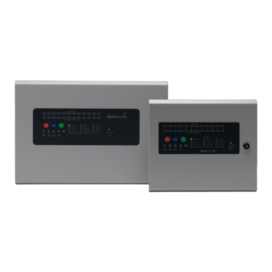
- Page 1 www.acornfiresecurity.com 4-12 Zone Conventional Control Panel Quick Start Guide The operation and functions described in this manual are available from Software Version 4.0 onwards. www.acornfiresecurity.com...
- Page 2 www.acornfiresecurity.com DoP QuickZoneXL 2831 EN54-2: 1997 +A1:2006 Control and indicating equipment for fire detection and fire alarm systems for buildings 544b/02 Provided options: Outputs to Fire Alarm Devices Investigation Delays to Outputs Dependency on more than one alarm signal Test Condition EN54-4: 1997 +A1:2002 +A2:2006 Power supply equipment for fire detection and fire alarm systems for buildings...
-
Page 3: Table Of Contents
www.acornfiresecurity.com Table of Contents Page INSTALLATION .............................. 4 MAINS CONNECTIONS ........................4 ........................4 ONNECTING THE ATTERIES GENERAL WIRING SCHEMATIC ......................5 PROGRAMMING OPTIONS ........................... 6 OPERATING ..............................7 PANEL CONTROLS & INDICATIONS ....................7 DISABLE MODE ............................ 8 TEST MODE ............................9 FAULT DIAGNOSIS .......................... -
Page 4: Installation
www.acornfiresecurity.com 1 INSTALLATION 1.1 MAINS CONNECTIONS Do not connect the mains supply to the panel until you are fully conversant with the layout and features of the equipment. A rating plate is attached to the power supply module describing the nature of the supply permitted. -
Page 5: General Wiring Schematic
www.acornfiresecurity.com 1.3 GENERAL WIRING SCHEMATIC _ _ + + MOTORISED BELL POLARISED APOLLO TWIN WIRE BASE 45681-206 TWIN WIRE CALL POINT MCP1B-R-TW 1 2 3 4 APOLLO TWIN WIRE BASE 45681-206 Note: On a Twin Wire circuit, the ELECTRONIC SOUNDER POLARISED sounders are connected in reverse polarity to the detectors... -
Page 6: Programming Options
www.acornfiresecurity.com 2 PROGRAMMING OPTIONS Option/Setting Description Code(s) View History View the last 40 events 1111 Set Fault Buzzer Volume Set the fault buzzer volume to high or low 2224 Clear All Disablements Remove all disablements which have been set for any 1121 zone, sounder circuit, output or delay Initialise Factory Settings... -
Page 7: Operating
www.acornfiresecurity.com 3 OPERATING 3.1 PANEL CONTROLS & INDICATIONS Activate Controls In normal standby mode the keypad controls are inactive to protect from unauthorised operation. Controls can be activated by using the ‘Activate Controls’ key switch or by entering a four digit code using the keypad. The use of a code entry to activate the controls is enabled by default but can be disabled in the Level 3 engineering functions. -
Page 8: Disable Mode
www.acornfiresecurity.com 3.2 DISABLE MODE Disable Mode is used to disable or isolate individual zone circuits or all sounder circuits, all auxiliary outputs and any delays to outputs. To initialise Disable Mode, firstly activate the controls by turning the key switch or by entering the four digit code. Then press and hold the Disable Mode button (1) for 3 seconds. -
Page 9: Test Mode
www.acornfiresecurity.com 3.3 TEST MODE Test Mode is used when testing the fire alarm system. In test mode the devices in the zone(s) in test, detectors and call points etc, can be activated and the panel will automatically reset, enabling the system to be tested by one person. -
Page 10: Fault Diagnosis
www.acornfiresecurity.com 3.4 FAULT DIAGNOSIS If the panel has detected a fault on the system, the General Fault LED will be illuminated and the internal fault buzzer will sound. Secondary LEDs will also be illuminated depending on the location of the fault. Pressing and holding the ENTER button will reveal more detailed information about the location and type of fault. -
Page 11: Service & Maintenance
www.acornfiresecurity.com 4 SERVICE & MAINTENANCE 4.1 SCHEDULE OF TESTING LOG BOOK This Section is to be used to record ALL Weekly Tests of The Fire Alarm System DATE & DEVICE TESTED & COMMENTS INITIALS OF LOCATION TESTER (IF ANY) TIME OF TEST www.acornfiresecurity.com... - Page 12 www.acornfiresecurity.com This page is intentionally left blanl www.acornfiresecurity.com...
-
Page 13: User Instructions
www.acornfiresecurity.com 5 USER INSTRUCTIONS If an alarm condition is present YOU MUST FOLLOW YOUR NORMAL FIRE DRILL PROCEDURES. A responsible person should then: Check the control panel to see which area or zone has caused the system to go into alarm. This will be indicated by a pulsing red LED on the front of the control panel. - Page 14 www.acornfiresecurity.com This page is intentionally left blank. www.acornfiresecurity.com...
- Page 15 www.acornfiresecurity.com USER NOTES www.acornfiresecurity.com...
- Page 16 Doc Number: 680-221 Advanced Electronics Ltd Revision: The Bridges, Balliol Business Park, Newcastle upon Tyne, NE12 8EW. UK Tel: +44 (0)345 894 7000 Email: sales@advancedco.com Web: www.advancedco.com www.acornfiresecurity.com...
Need help?
Do you have a question about the QuickZone XL Series and is the answer not in the manual?
Questions and answers