
Related Manuals for Advanced MxPro4 Mx-4200


Summary of Contents for Advanced MxPro4 Mx-4200
- Page 1 www.acornfiresecurity.com User Manual The operation and functions described in this manual are available from Software Version Mx4200V-023 and Mx4400V- 023 onwards. www.acornfiresecurity.com...
- Page 2 www.acornfiresecurity.com This page is intentionally left blank. www.acornfiresecurity.com...
-
Page 3: Table Of Contents
www.acornfiresecurity.com Contents INTRODUCTION TANDARDS AUTIONS AND ARNINGS ENERAL ESCRIPTION CONTROLS AND INDICATIONS RAPHICAL ISPLAY LED S TATUS NDICATORS ONTROL UTTONS AVIGATION UTTONS UMBER AND ETTER UTTONS UZZER OPERATION CCESS EVELS 3.1.1 Changing from Access Level 1 to Level 2 3.1.1.1 Menu Access 3.1.1.2 Control Buttons at Level 1... - Page 4 www.acornfiresecurity.com 3.9.3.2 Holiday / Inhibit 3.9.4 Enable - Groups 3.9.5 Enable - Change-Time 3.9.6 Enable - Remote 3.10 ESTING 3.10.1 Test - Zones 3.10.2 Test - Display 3.10.3 Test - Buzzer 3.10.4 Test - Printer 3.10.5 Test - Outputs 3.11 RINTING 3.11.1 Printer Communications Settings...
-
Page 5: Introduction
1 Introduction 1.1 Standards Advanced Electronics Ltd declare that the products identified below conform to the essential requirements specified in the Construction Products Directive 89/106/EEC: 0086-CPD-549125 EN54-2: 1997 +A1:2006 Control and indicating equipment for fire detection and fire alarm systems for buildings... -
Page 6: Cautions And Warnings
The Mx-4400V is a Multiple Loop, Analogue Addressable Fire Alarm Control Panel with provision for up to four loops. The Mx-4800V is a Multiple Loop, Analogue Addressable Fire Alarm Control Panel with provision for up to eight loops. All panels are designed for use with the ADVANCED / ARGUS VEGA ranges of fire detection devices www.acornfiresecurity.com... -
Page 7: Controls And Indications
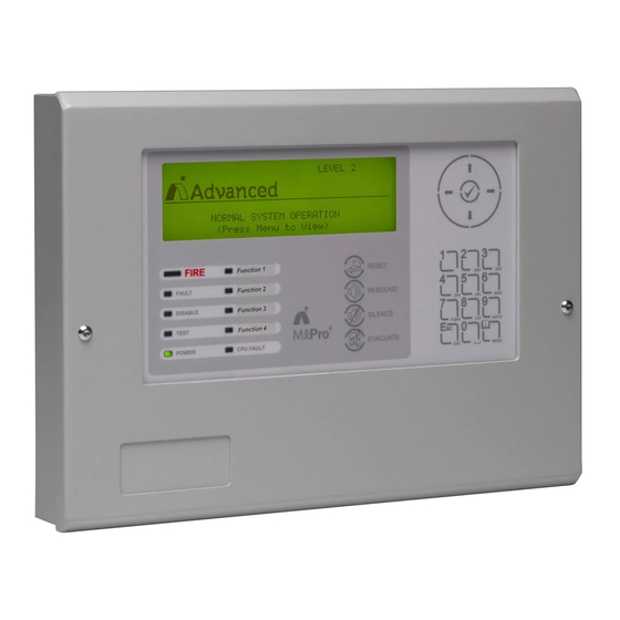
www.acornfiresecurity.com 2 Controls and Indications The Mx-4100, Mx-4200, Mx-4400 and Mx-4800 are provided with indications and control functions as shown in the diagram below and described in the following text. The Mx-4800 has two such display elements, one for loops 1-4 and the other for loops 5-8. Normal operator level indications, controls and user programming can all be achieved using either display. -
Page 8: Led Status Indicators
www.acornfiresecurity.com 2.2 LED Status Indicators The LED Status Indications show the basic operational state of the panel and whether the panel is in a fire alarm, fault, disabled or test condition. Function Colour Description FIRE Indicates that the system has detected a fire alarm condition (flashes on a new alarm and turns on steady when mute button is pressed). -
Page 9: Navigation Buttons
www.acornfiresecurity.com 2.4 Navigation Buttons Press to scroll through Menu Options. Press to display more information. Press to scroll through lists of zones or devices. Press to confirm entry of numeric or letter information entry. ✔ Press to confirm selection of a menu option. Press to change some of the configuration options. -
Page 10: Operation
www.acornfiresecurity.com 3 Operation 3.1 Access Levels The panel operation is protected from inadvertent and erroneous misuse by means of four access levels. These levels are as follows: Level 1 Untrained user Level 2 Authorised User Level 3 Service and Maintenance Engineer Service and Maintenance Engineer –... -
Page 11: Control Buttons At Level
www.acornfiresecurity.com [ CONTROLS DISABLED ] Please Enter Your Password Password Not Recognised ! 3.1.1.2 Control Buttons at Level 1 If any of the control buttons (Reset, Silence / Resound or Evacuate) are pressed, the display automatically prompts for the password. Enter the password as above 3.1.2 Changing from Access Level 2 to 1 If the panel has an access key switch fitted, use the key switch. -
Page 12: Detailed Fire Alarm Information
www.acornfiresecurity.com FIRE STARTED IN ZONE 0100 MAIN RECEPTION < Location Text for First Zone Evacuation Key <SWITCH > < Confirmation of Evacuation 1 Zone in Fire][Last Fire in Z0100] < No. of Zones in Fire & Last Zone < Zone Description for Last Zone MAIN RECEPTION 3.2.1 Detailed Fire Alarm Information Press the ... -
Page 13: Investigation Delays
www.acornfiresecurity.com 3.2.2 Investigation Delays The Investigation Delay Function can be disabled or enabled as required by EN54: 2. Refer to Section 3.8.4. If the Investigation Delay Function (Stage 1 / Stage 2 Investigation Delay) is enabled, a fire alarm is registered at the panel but does not immediately activate the sounders. -
Page 14: Fault Condition
www.acornfiresecurity.com 3.3 Fault Condition When the system registers a fault condition the Yellow Fault Indicator is illuminated, the internal buzzer sounds intermittently and the display shows the cause of the fault in more detail. An example of the display is shown below: ZONE 0001 DEVICE MISSING BASEMENT WEST... -
Page 15: Disablement Condition
www.acornfiresecurity.com 3.4 Disablement Condition If any zones, input devices or output devices have been disabled, the DISABLE Indicator is illuminated. In addition, the SOUNDER DISABLE Indicator is illuminated if one or more sounder circuits or devices have been disabled. The display indicates the presence of zone disablement conditions in the lower half of the display as follows: LEVEL 2 16:05... -
Page 16: Disabled Outputs
www.acornfiresecurity.com 3.4.2 Disabled Outputs The display presents a list of all of the zones in a disabled condition with the first disablement highlighted. For example: 2 Zones with Outputs Disabled] More> Zone Mode Location 0001 DISABLED BASEMENT WEST < Zones with location text where 0100 DISABLED RECEPTION <... -
Page 17: Menu Functions
www.acornfiresecurity.com 3.6 Menu Functions The following Menu Functions are available at Level 2. The display shows the primary Level 2 Menu and the Level 2 User as follows: [Level 2 Menu] User 1 Node VIEW DISABLE ENABLE TEST PRINT COMMISSION STATUS The following table gives a list of the Level 2 Menu Functions, the sub-functions available within each main function and a brief description for each function. -
Page 18: Using The Buttons To Navigate Menus
www.acornfiresecurity.com 3.6.1 Using the Buttons to Navigate Menus Press the ‘Menu’ button to bring up the display menu. 3.6.1.1 Selecting Menu Options The Level 2 Menu is shown below: [Level 2 Menu] User 1 Node VIEW DISABLE ENABLE TEST PRINT COMMISSION STATUS Press the ... -
Page 19: Viewing
www.acornfiresecurity.com 3.7 Viewing [View Menu] User 1 Node FIRES FAULTS ALARMS DISABLED INPUTS OUTPUTS PANEL NETWORK LOGIC Note that Fires, Faults, Alarms and Disablements are all normally shown without having to select the view menu. If, however, you wish to manually View any of these, they can be selected from this menu as required. 3.7.1 View - Fires This function shows the Zones and Inputs that are currently in a Fire Alarm condition. -
Page 20: View - Outputs
www.acornfiresecurity.com [ Inputs] More> Zone Mode Location 0001 Enabled BASEMENT WEST 0002 ALL DISABLED BASEMENT EAST 0008 Enabled GROUND FLOOR 0009 Enabled MAIN RECEPTION AREA Press the buttons to highlight the required zone and then press the button to view the full location text Press the ... -
Page 21: View - Panel
www.acornfiresecurity.com 3.7.7 View - Panel The View Panel Option provides a diagnostic readout of the operational condition and readings for the internal panel electronic circuits. When the option is selected, the display shows a list of the circuits. For example: [Panel Circuits] ITEM DESCRIPTION VALUE... -
Page 22: View - Log
www.acornfiresecurity.com 3.7.8 View - Log After selecting to view the log option the display presents a pop-up window to allow selection between a view of all of the event history, a view of only the fire alarms that have occurred or a view of the fire alarm counter. ALL EVENTS FIRE EVENTS ONLY ALARM COUNTER... -
Page 23: View - Logic
www.acornfiresecurity.com [NETWORK – Press 0 to Clear] More> Node Status LOCAL Level-2 Level-1 Additional network diagnostics are available by selecting the “More>” option. For further information, refer to the Ad-Net network manual (Document No. 680-027). Pressing '0' allows the stored network status information to be cleared. 3.7.10 View - Logic This is a diagnostic aid to assist engineers when first commissioning a complex fire system. -
Page 24: Disable - Outputs
www.acornfiresecurity.com To disable the entire zone, move over to the Mode column and highlight the existing mode. Press the ✔ button and a pop-up window appears showing the three possible options: - ALL INPUTS ALL EXCEPT CALL POINTS SELECTED INPUTS Press the ... -
Page 25: All Sounder Outputs
www.acornfiresecurity.com 3.8.2.1 All Sounder Outputs Press the buttons to scroll through and highlight the ALL SOUNDER OUTPUTS Option and then press the ✔ button to disable them. The display automatically reverts to the Main Disable Menu. The ‘Sounder Disabled’ Indicator will be illuminated. On networked systems, this only disables the outputs connected to this panel. -
Page 26: Disable - Delay-Mode
www.acornfiresecurity.com [Disable] User 1 Node ZONE/INPUTS OUTPUTS CONTROLS DELAY-MODE USER-ID GROUPS Press the buttons to highlight the Controls option and then press the ✔ button to select it. The display then prompts for password entry. Enter the password as normal. When a valid password has been entered, the control button functions and menu functions are disabled and the level 1 menu display will be shown: - [ CONTROLS DISABLED ]... -
Page 27: Disable - User Id
www.acornfiresecurity.com 3.8.5 Disable – User ID This operation will cancel the current User ID and return to the default User 1. User 1 can perform all actions except those defined as programmable (refer to the menu table). [Disable] User 5 Node ZONE/INPUTS OUTPUTS CONTROLS... -
Page 28: Enabling
www.acornfiresecurity.com 3.9 Enabling On selection of the Enable Menu Option, the display shows the available Enable Functions. [Enable] User 1 Node ZONE/INPUTS OUTPUTS GROUPS DELAY-MODE CHANGE-TIME REMOTE Press the buttons to highlight the required menu option and then press the ✔ button to select it. 3.9.1 Enable - Zones and Inputs Selecting this option will show a list of zones containing disabled input devices. -
Page 29: Enable - Groups
www.acornfiresecurity.com [Inhibit Delay End Date] TIME = 15:49 DATE = 02/07/08 WED 02 JUL 2008 Press the buttons to select the time / date fields. Enter the required time and date using the number buttons. Any pre-configured automatic delays or manual delays will be immediately suspended and the panel will operate without any investigation delays. -
Page 30: Enable - Remote
www.acornfiresecurity.com 3.9.6 Enable - Remote Information on the detectors connected to the panel and on the condition of all zones can be obtained with an ipGateway interface. In addition, the user can be assisted with operations such as disabling / enabling a detector from external commands over a TCP/IP system. -
Page 31: Testing
www.acornfiresecurity.com 3.10 Testing [Test Menu] User 1 Node ZONES DISPLAY BUZZER PRINTER OUTPUTS Press the buttons to highlight the required menu option and then press the ✔ button to select it. 3.10.1 Test - Zones The Test Zones function provides the means to implement a one-person walk test in order to test specific call points or detectors in one or more zones. -
Page 32: Test - Display
www.acornfiresecurity.com As an alternative to scrolling, a specific zone number can be entered by using the button to move to the zone number column, and then typing in the required number, followed by the ✔ button. If several consecutive zones are to be tested, an alternative to selecting them all individually is to specify a range of zones as follows: - Move to the zone number column and highlighting the first zone to test, then Press the ✔... -
Page 33: Test - Printer
www.acornfiresecurity.com 3.10.4 Test - Printer To invoke the printing of a test print sequence, highlight the Test Print Option and press the ✔ button to confirm. The panel transmits 16 lines of test characters to the printer. The information sent is echoed on the display. When the test print is completed, the display automatically reverts to the Test Options Menu. -
Page 34: Printing
www.acornfiresecurity.com 3.11 Printing [Print Menu] User 1 Node INPUTS OUTPUTS FAULTS DISABLED FEED-PAPER SETUP PRINTER 3.11.1 Printer Communications Settings The information is sent to the printer in a serial form. If an external printer is used, ensure that the communications settings in the printer are set as follows: Interface Type: RS232 Baud Rate: 9600... -
Page 35: Print Outputs
www.acornfiresecurity.com Press the key to start printing. The display will show the following whilst information is sent to the printer and printed. WORKING ... (Press Esc to Stop) After all information has been printed, the display will automatically revert to the Print Menu. Press the “Esc” key to stop printing if required. -
Page 36: Print - Log
www.acornfiresecurity.com 2 Zone(s) with Inputs Disabled] First Zone Last Zone (Press → to Start Print) If there are zones with outputs disabled: 1 Zone(s) with Outputs Disabled] First Zone Last Zone (Press → to Start Print) The panel analyses the network and the display will prompt the zones in a disabled condition. Use the arrow () buttons to highlight the first and last zone number and use the number keys to change the zone number as required. - Page 37 www.acornfiresecurity.com In the event of a fire alarm, call: - Quick Reference Guide TEL: For Service & Maintenance, contact: - TEL: Controls & Indications Navigation Buttons Graphic Liquid Navigation Crystal Display Buttons Press to scroll through Menu Options. Press to display more information.
- Page 38 www.acornfiresecurity.com This page is intentionally left blank. www.acornfiresecurity.com...
- Page 39 www.acornfiresecurity.com USER NOTES www.acornfiresecurity.com...
- Page 40 www.acornfiresecurity.com www.acornfiresecurity.com...
Need help?
Do you have a question about the MxPro4 Mx-4200 and is the answer not in the manual?
Questions and answers