
Related Manuals for Advanced Lux Intelligent LX-9400


Summary of Contents for Advanced Lux Intelligent LX-9400
- Page 1 www.acornfiresecurity.com Product Manual Addressable Emergency Lighting Control Panel The operation and functions described in the manual are available from Software Version Lx9400-090-03 onwards. www.acornfiresecurity.com...
- Page 2 www.acornfiresecurity.com Specifications: Item Specification Details Model LX-9400 LX-9400/D LX-9800 Enclosure Steel IP30, RAL 7035 Dimensions H x W x D mm 385 x 450 x 125 475 x 450 x 190 950 x 450 x 190 Weight (not including batteries) 8.6kg 12kg 23kg...
-
Page 3: Table Of Contents
www.acornfiresecurity.com Table of Contents Page INTRODUCTION............................. 6 ............................. 6 TANDARDS ........................6 AUTIONS AND ARNINGS ............................6 ESCRIPTION 1.3.1 System Features ..........................7 1.3.2 Luminaire Control / Monitor Modules ....................7 1.3.2.1 Lxp-302 Control / Monitor Module ......................7 1.3.2.2 Lxp-304 Light Monitor Module ......................... - Page 4 www.acornfiresecurity.com Test – Lights (Individually) ........................ 28 3.2.5.1.2 3.2.5.2 Test - Display ............................29 Test – Print ............................29 3.2.5.3 3.2.6 Viewing ............................30 3.2.6.1 View - Faults ............................30 3.2.6.2 View - Log ............................. 30 3.2.6.3 View Inputs ............................30 3.2.6.4 View Outputs ............................
- Page 5 www.acornfiresecurity.com 4.3.9.8 Config Data ............................52 SERVICE AND MAINTENANCE ........................53 ....................53 AINTENANCE NSPECTION CHEDULE 5.1.1 Daily Actions ............................ 53 5.1.2 Monthly Actions ..........................53 5.1.3 Quarterly Actions ..........................53 5.1.4 Annual Actions ..........................53 ......................54 EPLACEMENT OF OMPONENTS 5.2.1 Batteries ............................
-
Page 6: Introduction
Emergency Lighting Control Panel. Additionally, a User Guide (Document No. 680-070) is also available. The Lx-9400 is a Multiple Loop, Addressable Emergency Lighting Control Panel with provision for up to four signalling loops and is designed for use with Emergency Light Luminaires equipped with the Advanced Electronics Pulse addressing and monitor PLU module. -
Page 7: System Features
www.acornfiresecurity.com 1.3.1 System Features The Lux Intelligent system provides real-time monitoring and automatic testing of emergency lighting. It is designed to satisfy the requirements of BS5266 part 1 and prEN50172 standards for emergency lighting systems. Each Lux Intelligent control panel supports maintained, non-maintained and slave luminaires in either self- contained central battery or static inverter systems. -
Page 8: Lxp-304 Light Monitor Module
www.acornfiresecurity.com 1.3.2.2 Lxp-304 Light Monitor Module The Pulse Light Only Line Unit is a device which checks for correct light levels, but does not monitor a battery or AC supply and provides the following major features: Self (Soft) Addressing – No DIL Switches to set in the luminaire fitting ... -
Page 9: Installation Approvals
www.acornfiresecurity.com 1.4 Installation Approvals 1.4.1 Emergency Lighting Installations The panel must be installed and configured for operation in accordance with these instructions and the applicable code of practice or national standard regulations for emergency lighting systems installation appropriate to the country and location of the installation. 1.4.2 Wiring Regulations The panel and system must be installed in accordance with these instructions and the applicable wiring codes... -
Page 10: Installation
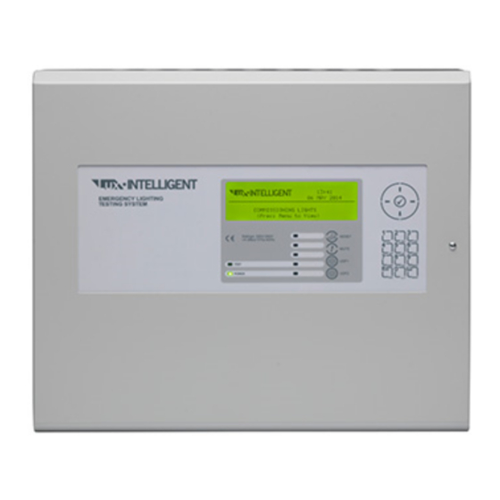
www.acornfiresecurity.com 2 Installation 2.1 Identification of Parts The diagram opposite shows the major parts of the panel. 2.2 Installing the Lx-9400 Enclosure The panel can weigh in excess of 20kg when the batteries are installed. Use the appropriate fixing hardware necessary to secure the panel to the wall. Observe recommended lifting practices to guard against spinal injury. -
Page 11: Mounting The Enclosure
www.acornfiresecurity.com 2.2.3 Mounting the Enclosure Firstly, remove the required knockouts for the Enclosure Size and Fixing Point Dimensions installation wiring. There are sufficient knockouts 9400 on the top of the enclosure for all installation wiring. In addition, there are knockouts at the top of the back wall, if required, for rear entry cabling. -
Page 12: Recommended Cable Routing Arrangement
www.acornfiresecurity.com 2.2.5 Recommended Cable Routing Arrangement Internal arrangement showing recommended routing of cables. It is recommended that the 9400, 9400/D 9800 routing arrangement shown in the diagrams opposite be employed. Use rear Use front knockout rows Segregate the SELV low knockout rows for lower chassis for upper... -
Page 13: Installing Additional Option Modules
www.acornfiresecurity.com 2.2.6 Installing Additional Option Modules Isolate ALL sources of power before installing or removing printed circuit boards. Observe anti-static precautions at all times when handling printed circuit OBSERVE PRECAUTIONS boards. FOR HANDLING ELECTROSTATIC SENSITIVE DEVICES 2.2.6.1 Additional Signalling Line Circuits To extend the number of signalling line circuits / loops or to replace an existing loop driver card (Lxp-901) follow the procedure described below. -
Page 14: Integral Modem Option
www.acornfiresecurity.com 2.2.6.3 Integral Modem Option The modem card option may be supplied factory installed when the control panel is ordered. It is mounted on the chassis plate, on pre-installed pillars, to the left of the base card. 4x M3 Screws are used to secure the card to the chassis. -
Page 15: Printer Diagnostics
www.acornfiresecurity.com 2.2.6.5.2 Printer Diagnostics LED state Description Steady Flash (once per second) Normal operation No power. Check that the ribbon cable connecting the printer to the display has been fitted. Rapid Flash Printer not ready. Check: - (Four times per sec) Paper roll inserted Paper holder door fully closed Battery pack not connected... -
Page 16: Wiring Installation
www.acornfiresecurity.com 2.3 Wiring Installation All electrical wiring installation work should be carried out in accordance with the code of practice or applicable national standards appropriate to the country of installation. To maintain electrical integrity of the SELV wiring on the input, output, loop and communications lines all SELV wiring should be segregated from the LV mains wiring and be wired using cable with insulation suitable for the application. -
Page 17: Battery Installation
www.acornfiresecurity.com 2.3.2 Battery Installation The panel requires two 12V batteries for standby operation. The battery leads are connected onto the base card via a two-part plug and socket, as shown in the diagram opposite. Refer to the Specifications for minimum and maximum battery sizes allowed. -
Page 18: Signalling Line Installation
www.acornfiresecurity.com 2.3.3 Signalling Line Installation 2.3.3.1 General Considerations The Line Driver Module, shown opposite, provides power and signalling pulses for the digital communications with the luminaires. Up to four Line Drivers can be installed in the panel. Refer to Section 2.2.6 for details of how to install additional line drivers. -
Page 19: Loop Wiring Format
www.acornfiresecurity.com If a screened cable is used in a radial circuit, the screen at the end of the cable run should also be connected to earth. If there is a voltage potential difference between the panel earth and the remote earth point, connect the screen to the earth point via a 2.2F polyester (non-polarised) capacitor of suitable voltage rating. -
Page 20: User Operation
www.acornfiresecurity.com 3 User Operation 3.1 Controls and Indications The Lx-9400 is provided with indications and control functions as shown in the diagram below and described in the following text. Normal operator level indications, controls and user programming can all be achieved using either display. -
Page 21: Led Status Indicators
www.acornfiresecurity.com 3.1.2 LED Status Indicators The LED Status Indications show the basic operational state of the panel. Function Colour Description Power Green Indicates the presence of power Function 1 Spare function LED Function 2 Yellow Spare function LED Function 3 Yellow Spare function LED Function 4... -
Page 22: Number And Letter Buttons
www.acornfiresecurity.com 3.1.5 Number and Letter Buttons A B C D E F G H I J K L M N O Used to enter numbers or letters. P Q R S T U V W X Y Z E S C M E N U Press to return to a previous menu. -
Page 23: Changing From Access Level 2 To 1
www.acornfiresecurity.com Enter the password using the number buttons and then press the ✔ button. As each number is entered, an asterisk (*) is shown on the display. For example: [ CONTROLS DISABLED ] Please Enter Your Password If the password is correct, the Level 2 Menu options will be shown. If the password is incorrect, the display briefly shows the following message. -
Page 24: Alarm Condition
www.acornfiresecurity.com Press the buttons to highlight the required zone in fault and then press the button to show further information. For example: Faults in Zone 0003 ] More> LP ADRS STATE 1 008.0 DEVICE MISSING < Address, fault condition Press the ... -
Page 25: Menu Functions
www.acornfiresecurity.com 3.2.4 Menu Functions The following Menu Functions are available at Level 2. The display shows the primary Level 2 Menu as follows: [LIGHT MONITORING SYSTEM – (Level 2)] TEST VIEW LOCK CONTROLS TIME/DATE STATUS COMMISSION The following table gives a list of the Level 2 Menu Functions, the sub-functions available within each main function and a brief description for each function. -
Page 26: Selecting Individual Zone Numbers
www.acornfiresecurity.com For example, press the button twice followed by the button to highlight the COMMISSION option (as shown below) and then press the ✔ button to select this option. [LIGHT MONITORING SYSTEM – (Level 2)] TEST VIEW LOCK CONTROLS TIME/DATE STATUS COMMISSION... -
Page 27: Test - Lights
www.acornfiresecurity.com 3.2.5.1 Test – Lights The luminaires can be tested manually in their groups or individually. [TEST LIGHTS] GROUP INDIVIDUAL Highlight the required option and press the ✔ button to select. 3.2.5.1.1 Test – Lights (By Group) Select the Group option and the display shows the status of any completed tests and any tests currently in progress. -
Page 28: Test - Lights (Individually)
www.acornfiresecurity.com [TEST GROUP <More Lp:Adrs Duration Date Time 1:011 1 mins 11 FEB 2004 14:26 1:012 5 mins 11 FEB 2004 14:26 1:026 1 mins 11 FEB 2004 14:26 1:045 2 mins 11 FEB 2004 14:26 Press the button to view the duration from the start of the test at which the failure was detected and the date and time that the tests started. -
Page 29: Test - Display
www.acornfiresecurity.com 3.2.5.2 Test - Display The Test Display option checks the operation of all the Indicators and the Graphic Display. All of the Indicators are turned on and the entire display is shown in reverse. During this test, it is possible to test the operation of the ,,,,✔ and 0-9 buttons. When a button is pressed, it is indicated on the display. -
Page 30: Viewing
www.acornfiresecurity.com 3.2.6 Viewing [View Menu] FAULTS PANEL INPUTS OUTPUTS NETWORK 3.2.6.1 View - Faults This function shows the Zones, Inputs and Outputs that are currently in a Fault condition. The operation of the panel and the information that can be shown is identical to the views available from the main operating display. -
Page 31: View Outputs
www.acornfiresecurity.com [ Inputs] More> Zone Mode Location 0001 Enabled BASEMENT WEST 0002 Enabled BASEMENT EAST 0008 Enabled GROUND FLOOR 0009 Enabled MAIN RECEPTION AREA Press the button to view the full location text. [ Inputs] More> Zone Mode Location 0001 Enabled BASEMENT WEST 0002 Enabled... -
Page 32: View - Panel
www.acornfiresecurity.com 3.2.6.5 View - Panel The View Panel Option provides a diagnostic readout of the operational condition and readings for the internal panel electronic circuits. When the option is selected, the display shows a list of the circuits. For example: [Panel Circuits] ITEM DESCRIPTION VALUE... -
Page 33: View - Network
www.acornfiresecurity.com 3.2.6.6 View - Network This Option can be used to obtain diagnostic information when a network is used to connect other panels or remote terminals. The access level of all panels on the network can be checked from this display: [NETWORK –... -
Page 34: Print
www.acornfiresecurity.com 3.2.10 Print The print menu provides facilities to print any test results, the event log, etc. [Test Menu] TEST-RESULTS FEED-PAPER STOP SETUP-PRINTER Select the required print function. The details for each print function are described below. 3.2.10.1 Print – Test Results On selection, the display shows a list of the group tests completed (either manually or automatically) as follows: [LIGHTING TEST GROUPS] More>... -
Page 35: Print - Log
www.acornfiresecurity.com 3.2.10.2 Print – Log On selection, the display cycles through each log entry and prints this record on the printer. When the Log print is completed, the display automatically reverts to the Print Options Menu. Press the Esc button, at any time, to stop and cancel the printout. 3.2.10.3 Print –... -
Page 36: Printer Diagnostics
www.acornfiresecurity.com 3.2.10.6 Printer Diagnostics LED state Description Steady Flash (once per second) Normal operation No power. Check that the ribbon cable connecting the printer to the display has been fitted. Rapid Flash Printer not ready. Check: - (Four times per sec) Paper roll inserted Paper holder door fully closed Battery pack not connected... -
Page 37: Programming
www.acornfiresecurity.com 4 Programming 4.1 Introduction These instructions cover the configuration and programming of the panels. A level-3 password is required to enter the commissioning menus. For details of Passwords, refer to Section 4.3.7. Level-3 Passwords. If this number is lost, it is not possible to enter commission mode functions. Refer to Section for further formation. -
Page 38: Numeric Data Entry
www.acornfiresecurity.com >RESTAURANT < KEY IN THE REQUIRED TEXT The method of entering the characters is similar to the method employed on mobile telephones. The number buttons provide both their appropriate number and several letters of the alphabet. An example of the keypad is shown opposite. For example, Button 2 allows entry of the number 2 and letters A, B and C. -
Page 39: Recommended Programming Procedure
www.acornfiresecurity.com 4.2 Recommended Programming Procedure The following steps are recommended when installing a system control panel for the first time. Step Menu Action – SET-UP Define General Set-up Information (Phone Numbers, etc.). – PASSWORDS Define Level 2 and Level 3 Passwords as required. –... -
Page 40: Loops
www.acornfiresecurity.com 4.3.1 Loops On selecting the LOOPS option, the display will prompt for the loop to be viewed / programmed. For example: - [Select Loop] 1st-Loop 2nd-Loop 3rd-Loop 4th-Loop The list of loops available will be adjusted automatically to show only those loops that have a loop driver card installed. - Page 41 www.acornfiresecurity.com Lxp-302 [Addr 001.0](✔ to Start Test) <More SETTING READING Serial No 0226492433 Type NON-MAINT. Mains Off Light (Off) 12 Min Battery 4 Cell NiCad Lxp-304 Light Only [Addr 002.0](✔ to Start Test) <More SETTING READING Serial No 0226492434 Type NON-MAINT.
-
Page 42: State
www.acornfiresecurity.com 4.3.1.1.1 State This parameter shows the current operational status of the device. For example, this can show Normal, Reset, Not In Use, Device Missing, etc. This parameter cannot be changed. 4.3.1.1.2 Test Group The luminaire should be allocated to a test group for both automatic and manual testing. Up to 50 test groups can be used. -
Page 43: Light
www.acornfiresecurity.com For the Lxp-110 I/O Module, there are two sub addresses for each device, one for the output (type = RELAY) and one for the input (type = SWITCH). 4.3.1.1.7 Light The minimum light level is the analogue value of the light intensity measured by the PLU below which a lamp failure indication will be indicated. -
Page 44: I/O Module Input Action
www.acornfiresecurity.com 4.3.1.1.9 I/O Module Input Action The operation of the input can be assigned to the following actions: Action Description Group Test I/P The panel will invoke a test on the test group assigned to this switch when the switch input is active. The Panel display shows “Warning”... -
Page 45: Loops - Auto Learn
www.acornfiresecurity.com 4.3.1.2 Loops - Auto Learn 4.3.1.2.1 Normal Procedure / Initial learn The panel can automatically learn the presence or absence of devices at all addresses (where soft addresses have been assigned) connected to the loop. When the Auto Learn option is selected, the panel starts searching each address on the loop to locate and find all of the devices connected. -
Page 46: Procedure If The Panel Finds Devices Added
www.acornfiresecurity.com 4.3.1.2.3 Procedure if the Panel finds Devices Added When the panel finds a device not previously learnt and programmed in the panel, the Auto Learn process is suspended and the display shows a pop-up window with options. For example: ACCEPT NEW DEVICE REJECT NEW DEVICE ACCEPT ALL NEW DEVICES... -
Page 47: Search All Plu
www.acornfiresecurity.com 4.3.1.3.1 Search All PLU This is the main procedure to follow when installing a new installation or adding a luminaire(s) to the installation. The display first shows the address ranges as it searches for each PLU installed on the signalling line as follows: [SEARCH PLUs] 0 Found... -
Page 48: Loops - Driver
www.acornfiresecurity.com 4.3.1.4 Loops – Driver This function displays loop output and input voltages and loop loading. A diagnostic display with automatic scanning of the loop to find devices with minimum and maximum communication pulse heights is available. Press the button to select this view. 4.3.2 Zones The Commission Zones option lists all the zones in use by the panel and allows the zone text description to be... -
Page 49: Tests
www.acornfiresecurity.com 4.3.4 Tests The panel provides the programming capability to define up to 400 different tests to be automatically performed at specific dates. Select the TESTS option and the display will show: - [LIGHT AUTO TESTS] Test Group Date(dd/mm) Time Period Press the ... -
Page 50: Time And Date
www.acornfiresecurity.com 4.3.5 Time and Date This function can be used to change the time and date in the panel and is the same as detailed in the User Operation Section. A confirmation password is not required when selecting from the Commissioning Level. 4.3.6 View Options The View Menu Options are identical to those available during Level-2 operation. -
Page 51: Pc Config
www.acornfiresecurity.com 4.3.8 PC Config The PC Link Option enables the connection of the PC Configuration Tool for retrieving configuration data from the panel and programming configuration data from a file on the PC. For further information, refer to the Manual supplied with the PC Configuration Tool. 4.3.9 Setup The Setup Options Menu enables the configuration of panel generic operating parameters. -
Page 52: Trace Logging Mode
www.acornfiresecurity.com 4.3.9.5 Trace Logging Mode The Trace Logging Option determines what type of information and to what level is stored in the Event Log. There are three options: STANDARD = the normal operating mode logging fault and warning conditions as they occur. STANDARD + = an extended version of the standard operating mode where the removal of fault and warning conditions are also logged. -
Page 53: Service And Maintenance
www.acornfiresecurity.com 5 Service and Maintenance 5.1 Maintenance / Inspection Schedule The following is taken from an extract of ICEL 1008 Emergency Lighting Risk Assessment Guide 2001 (Appendix D & Section 11) It is important that equipment is properly tested & maintained if it is to function correctly when required in an emergency. -
Page 54: Replacement Of Components
www.acornfiresecurity.com 5.2 Replacement of Components In general, all of the components parts used in the construction of the panel have been selected for long life and reliability. However, certain components may require to be changed on a regular service basis. The details of these are as follows: 5.2.1 Batteries... -
Page 55: Liquid Crystal Display
www.acornfiresecurity.com 5.2.2 Liquid Crystal Display Expected Life: > 10 years Replacement Schedule: When the display becomes difficult to read. The display contrast will gradually fade with time. Manufacturer / Part Number: Replace the complete display / keyboard assembly. Spare part number MXS 004. -
Page 56: Appendices
www.acornfiresecurity.com 6 Appendices 6.1 Appendix 1 – Forgotten Level 3 Password Should the Level-3 password be forgotten, contact Customer Support to obtain a temporary permit number to regain access to the panel programming functions. Customer Support will require a decryption key displayed by the panel. To obtain this number, attempt to gain access to the Level-3 Programming Functions entering “1”... -
Page 57: Appendix 2 - Recommended Cables
www.acornfiresecurity.com 6.2 Appendix 2 – Recommended Cables Signalling Circuits All cables are Belden twisted pair (or equivalent). 8762, 8760 & 8719 types are screened, twisted pair and are recommended where a high level of high frequency electrical noise is prevalent in the installation. 8205, 8461 &... -
Page 58: Appendix 3 - Battery Standby Calculation Chart
www.acornfiresecurity.com 6.3 Appendix 3 – Battery Standby Calculation Chart Use the following charts and associated notes to calculate the size of the batteries required to ensure operation of the installation in the event of AC Mains power failure. Load Current Equipment I (A) Total... -
Page 59: Appendix 3 - Commission Record Sheet
www.acornfiresecurity.com 6.4 Appendix 3 – Commission Record Sheet www.acornfiresecurity.com... - Page 60 www.acornfiresecurity.com This page is intentionally left blank. www.acornfiresecurity.com...
- Page 61 www.acornfiresecurity.com USER NOTES www.acornfiresecurity.com...
- Page 62 www.acornfiresecurity.com www.acornfiresecurity.com...
Need help?
Do you have a question about the Lux Intelligent LX-9400 and is the answer not in the manual?
Questions and answers