
Related Manuals for Advanced ExGo Ex-3001


Summary of Contents for Advanced ExGo Ex-3001
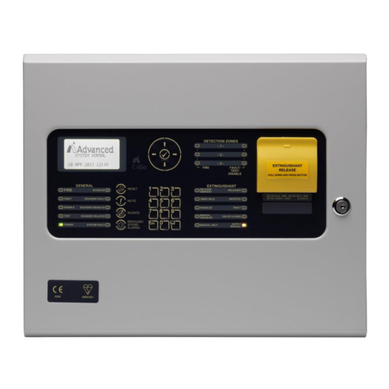
- Page 1 Extinguishing Control Panel Installation and Commissioning The operation and functions described in this manual are available from Software Version Ex-3000-V2.05C onwards. www.advancedco.com...
- Page 2 Specifications: Item Specification Details Part Number Ex-3001 Enclosure Steel IP30, RAL 7035 Dimensions H x W x D mm 330 x 400 x 90 Class A – Indoor IP30 0°C to 40°C Environmental Class Humidity 95 % Max Weight (excluding batteries) 5.1Kg Cable Entries (20mm knockouts) 17x top and 13x top rear...
-
Page 3: Table Of Contents
Table of Contents Page INTRODUCTION TANDARDS AUTIONS AND ARNINGS ESCRIPTION EN54 F UNCTIONS 1.1.1 EN54 Optional Features with Requirements EN12094 F UNCTIONS 1.2.1 EN12094-1 Optional Features with Requirements NSTALLATION PPROVALS 1.3.1 Fire System Installations 1.3.2 Wiring Regulations INSTALLATION DENTIFICATION OF ARTS NSTALLING THE BACK BOX IRING... - Page 4 3.3.8 Status Indicators 3.3.9 Enable PC LINK 3.3.10 Exit SERVICE AND MAINTENANCE AINTENANCE CHEDULE 4.1.1 Daily Actions 4.1.2 Monthly Actions 4.1.3 Quarterly Actions 4.1.4 Annual Actions EPLACEMENT OF OMPONENTS 4.2.1 Batteries 4.2.2 Liquid Crystal Display APPENDICES 1 – F PPENDIX ORGOTTEN EVEL ASSWORD...
-
Page 5: Introduction
1 Introduction 1.1 Standards Advanced Electronics Ltd declare that the ExGo Gas Extinguishing Control Panel conforms to the essential requirements specified in the Construction Products Directive 89/106/EEC: Refer to the full CPD schedule on the back page. EN12094-1:2003 EN54-2:1997 +A1:2006... -
Page 6: En54 Functions
1.1 EN54 Functions This Control Panel is compliant with the requirements of EN54-2: 1997 +A1: 2006 and EN54-4: 1997 +A1: 2002 +A2: 2006. In addition to the basic requirements, the following optional functions are provided and these comply with the requirements of EN54. CIE Optional Functions EN54-2 Clause Outputs to Fire Alarm Devices... -
Page 7: En12094 Functions
Total Loss of Power. The CIE has provision to annunciate a total loss of power for one hour. Refer to Section 3.3.7 for information on configuring this option. Section 8.4 Conditions: - Requires installation of 7Ah batteries - The minimum battery operating voltage is 20.4V - Output Power AUX2 must not be used for external equipment. - Page 8 Emergency Hold Device. The ECD has provision for an emergency hold device. Refer to Sections 2.3.5.6, 3.3.4 and 3.3.3.1. Section 4.20 Means shall be provided to transmit the information concerning the activation of an emergency hold device. Refer to sections 2.3.5.1 and 3.3.5 for further information. Control of Flooding Time.
-
Page 9: Installation Approvals
1.3 Installation Approvals 1.3.1 Fire System Installations The panel must be installed and configured for operation in accordance with these instructions and the applicable code of practice or national standard regulations for fire systems / extinguishing system installation (for example BS5839-1: 2002, BS7273-1: 2006) appropriate to the country and location of the installation. 1.3.2 Wiring Regulations The panel and system must be installed in accordance with these instructions and the applicable wiring codes... -
Page 10: Installation
2 Installation 2.1 Identification of Parts The following diagram shows the major parts of the panel. AC INPUT RELAY MODULE PSU MODULE (OPTIONAL) LIVE EARTH NEUTRAL u P M O D E P S U U S B C o m m s R U N P R O G R e l a y - 1... -
Page 11: Installing The Back Box
2.2 Installing the back box Enclosure dimensions and fixing points are shown in the diagram below. Remove the chassis before installing the enclosure (retain in a safe place). LIVE EARTH NEUTRAL When batteries are installed, the ExGo can weigh in excess of 10Kg. Use appropriate fixing hardware to secure the panel to the wall. -
Page 12: Wiring Installation
2.3 Wiring Installation 2.3.1 AC Mains Wiring The power supply is classified as Class1 equipment construction and must be earthed in PSU Internal Mains Field Connections accordance to EN60950 recommendations. Wiring FUSE Brown Route the high voltage mains AC wiring into the LIVE enclosure using a suitable knockout and keeping Grn/Yel... -
Page 13: 24Vdc Power Supply Wiring
2.3.3 24VDC Power Supply Wiring The main printed circuit card on the chassis is supplied with 24V DC from the power +V DC POWER supply. 0V DC POWER BATTERY + BATTERY – In addition, the operating status of the power supply is communicated to the main electronics via a serial link. -
Page 14: Relay Outputs
2.3.5.1 Relay Outputs Fault Output. The Fault Relay is arranged for failsafe operation as standard. Section 8.8 The panel is equipped with four relay outputs. See diagram opposite for terminal block positions. Each output is unsupervised with volt-free changeover contacts rated at 30V AC/DC, 1A, resistive. -
Page 15: Aux Dc Supply Output
2.3.5.3 AUX DC Supply Output Two Auxiliary Power Outputs are provided. AUX-2 AUX-1 18.0 – 28.0 V DC, 0.5A SUPERVISED. POWER LIMITED. AUX #1 : 4-Wire Smoke Detector Power or other similar application. Power turns off for 4-5 seconds on reset and when EN54- 2 Clause 8.4 limit is reached. -
Page 16: Sounder / Monitored Output Circuits
HAZARDOUS AREA 2.3.5.4.3 Intrinsic Safe Arrangement IS Detector IS Detector IS Call Point Isolation Barrier The Zone Circuit can be configured for use with Intrinsic Safety detectors and barriers – see – programming section. The recommended isolation barrier is a PEPPERL+FUCHS Model: KFDO-CS-Ex1.51P or MTL Model: 5061 SAFE AREA... - Page 17 2.3.5.5.2 EN54-13 Monitoring The sounder outputs support monitoring with an Active EOL device to ensure circuit integrity in accordance with the requirements of EN54-13. The sounder circuits can be configured for compliance with EN54-13 by programming and the use of an Active EOL device. All panel sounder outputs must be fitted with the Active EOL device (Mxp-505) The panel uses techniques to ensure that a...
-
Page 18: Input Circuits
2.3.5.6 Input Circuits Seven Fixed function Input circuits are provided for the following functions: MODE SELECT [Auto / Manual], MANUAL TRIGGER, HOLD, ABORT, PRESSURE MONITOR, VALVE MONITOR and FLOW MONITOR. Four Programmable Function Input Circuits are P S U provided. Each input circuit is monitored for open C o m m s and short circuit conditions –... -
Page 19: Usb
2.3.5.7.1 Igniting Actuators Up to 4 igniting actuators in series The circuit is current limited and one to four igniting actuators can be wired in series without special requirements. No additional resistance is required in the circuit Maximum line impedance 7Ω including the internal resistance of the actuators. -
Page 20: Recommended Cable Routing
2.3.5.9 Recommended Cable Routing The following diagram shows the recommended cable routing within the enclosure. Zone Inputs Actuator AC IN Output Sounder Outputs Inputs Relays 485 / AUX AC INPUT Cable Tie LIVE EARTH NEUTRAL u P M O D E P S U U S B C o m m s... -
Page 21: Key-Switch Installation
2.4 Key-Switch Installation u P M O D E P S U U S B C o m m s R U N P R O G R e l a y - 1 R e l a y - 2 F I R E F A U L T R S 4 8 5... -
Page 22: Loading Calculations
2.6 Loading Calculations 2.6.1 Panel Loading The Total Panel Load must not exceed the rating of the power supply. The power supply can deliver a 2A total load maximum. The panel loading includes the panel itself (70/125mA), any power required for additional option modules and all external power required for the Input, Output and AUX circuits. -
Page 23: Programming
3 Programming 3.1 Introduction These instructions cover the configuration and programming of the panels. NOTE: The panel is delivered in a non-configured condition. In this mode (or if the panel is returned to factory default settings) the panel defaults to MANUAL ONLY mode of operation. After configuring the panel, use the Level 2 EXTINGUISH MODES menu option (or the configured key-switch / inputs) to set the panel into the AUTO+MANUAL mode. -
Page 24: Enable Controls
Normal Display Non-normal Display Typical Menu Display [System status] [Level 2 Menu] 1 of 1 conditions: VIEW DETECTION ZONE3 TEST SYSTEM NORMAL OPEN CIRCUIT EXTINGUISH MODES DISABLE/ENABLE [Release status] 22 AUG 2007 16:39:00 EXIT LEVEL 2 UNAFFECTED Release Imminent Release Activated Release Complete [Release status] RELEASE ACTIVATED... -
Page 25: Numeric Data Entry
3.1.5 Numeric data entry Numbers are entered by moving to the required field, and then typing in the required number, followed by the button. The display returns to the previous menu. If the number is entered incorrectly, press the button to clear the entry and then re-enter the required number. -
Page 26: Detection Zones
3.3.1 Detection Zones This menu configures each of the three detection zone input circuits. Highlight the DETECTION option and press the button. The following Zone Select Menu will be shown. Use the buttons to highlight the required zone and [Zone Select] then press the ... -
Page 27: Sounder Configuration
This menu configures each of the three alarm output circuits. Highlight the ALARM OUTPUTS option and press the button. The following Sounder Select Menu will be shown. [Sounder Select] Sounder-1 (Fire) Use the buttons to highlight the required sounder (or Sounder-2 (Fire) the pulse pattern option) and then press the ... -
Page 28: Pulse Pattern Configuration
Triggering Signals to Equipment within the System. The general fire alarm outputs can be used / configured to transmit triggering signals to extinguishing system equipment such as pilot cylinders, warning devices, etc. If required, the outputs can be non-silencing. These outputs can be individually Section 4.24 disabled (sounder-1 / sounder-2). -
Page 29: Extinguishing
3.3.3 Extinguishing The Extinguishing Menu comprises three separate sub-menus. These cover the operating parameters of the actuator output (Output Set-Up), the fire alarm and manual conditions required to activate the output (Cause & Effect) and operating parameters for any Extract output (Extract Set-Up). [Extinguish Select] Output Set-Up Cause &... -
Page 30: Extract Set-Up
Some options are mutually exclusive. Depending on the [Extinguish C&E] options selected, some options are inhibited and cannot be Release Active When:- adjusted – the current setting is shown as ‘- -‘. TWO Z1&Z2 : √ TWO Z1&Z3 The settings only apply to the AFD inputs. A Manual Trigger input will immediately generate the activated TWO Z2&Z3 condition. -
Page 31: Inputs
3.3.4 Inputs The display presents a list of the programmable inputs along with their current settings. Use the buttons to highlight the required input and [Input Settings] then press the button to select / change it. PROG INPUT 1: NOT IN USE The table below details each available input and the PROG INPUT 2:... -
Page 32: Outputs
3.3.5 Outputs The display presents a list of the programmable outputs along with their current settings. Use the buttons to highlight the required output and then [Prog. Outputs] press the button to select / change it. RELAY 1 >... -
Page 33: Switched Aux Output
Outputs Setting Options Comments MANUAL TRIGGER The output is activated whenever a manual trigger has been used to initiate the release of gas. Remains active until a successful Gas Reset. 3.3.5.1 Switched AUX Output The Switched AUX Output is normally turned on and will turn off for about 5 seconds when the panel is reset. This is useful for resetting conventional beam detectors, etc. -
Page 34: General Options
3.3.7 General Options The display presents a menu of user general options. Parameter Comments / Description Options Default Setting 0 – 5 Minutes The Level 2 Time Out can be configured in the range 0 – 5 Level 2 Time Out 5 Minutes minutes (0 = No time out –... -
Page 35: Status Indicators
Parameter Comments / Description Options Default Setting JAN – DEC Forward Month Specifies in which month the time will be shifted forwards by 1 hour . Back Order Specifies which occurance of the day specified (below) in LAST the month specified (below) the time will be shifted back by 1 hour (at 2AM the time will change to 1AM). -
Page 36: Enable Pc Link
3.3.9 Enable PC LINK The ENABLE PC LINK menu option allows a PC to be connected to the panel for upload / download. [USB Port Enabled] The display shows the current status of the link. Possible status messages are: CURRENT STATUS: LOGO UPDATE (<... -
Page 37: Service And Maintenance
4 Service and Maintenance 4.1 Maintenance Schedule This equipment should be maintained in accordance with the regulations and codes appropriate to the country and location of installation. The following is recommended if no other regulations apply. 4.1.1 Daily Actions The site operator / user should perform the following checks and actions: a) The panel indicates normal operation. -
Page 38: Replacement Of Components
4.2 Replacement of Components In general, all of the components parts used in the construction of the panel have been selected for long life and reliability. However, certain components may require to be changed on a regular service basis. The details of these are as follows: 4.2.1 Batteries For battery installation, see section 2.3.2... -
Page 39: Appendices
5 Appendices 5.1 Appendix 1 – Forgotten Level 3 Password Should the Level-3 password be forgotten, contact Customer Support to obtain a temporary permit number to regain access to the panel programming functions. Customer Support will require a decryption key displayed by the panel. To obtain this number, attempt to gain access to the Level-3 Programming Functions entering “1”... -
Page 40: Appendix 2 - Compatible Devices
5.2 Appendix 2 – Compatible Devices 5.2.1 Detectors № / № / Zone Manufacturer Part Number Description Zone (Schottky bases) Apollo 55000-215 Series-65 Ion smoke 55000-216 Series-65 Ion smoke 55000-217 Series-65 Ion smoke 55000-218 Series-65 Ion smoke (Integrating) 55000-219 Series-65 Ion smoke (Integrating) 55000-220 Series-65 Ion smoke (Integrating) 55000-315... - Page 41 № / № / Zone Manufacturer Part Number Description Zone (Schottky bases) DCD-CE3 CDX Heat DFG-60E CDX Heat DFJ-AE3 CDX Heat DFJ-CE3 CDX Heat HF-24 UV Flame SPC-ET CDX Beam SPB-ET CDX Beam SRA-ET CDX Beam Nittan EVC-P Evolution Photo-smoke EVC-H-A2S Evolution Heat EVC-H-CS...
-
Page 42: Appendix 3 - Recommended Cables
5.3 Appendix 3 – Recommended Cables 5.3.1 Fire Rated Cables For best performance, the prefered cables are 2-core twisted with overall shield. Core Sizes (mm) 5839-1 Rated Manufacturer Cable Type (30) (120) (In alphabetical order) Firetec Multicore Standard. FS2C ... -
Page 43: Appendix 4 - Troubleshooting
5.4 Appendix 4 – Troubleshooting Symptom Cause/ Solution This indicates that the actuator type has not been ‘learnt’ – or that a The display shows the condition wiring fault caused the learn process to be aborted. “ACTUATOR CIRCUIT” The control panel must determine the exact characteristics of the actuator “... - Page 44 This page is intentionally left blank. www.advancedco.com...
- Page 45 This page is intentionally left blank. www.advancedco.com...
- Page 46 This page is intentionally left blank. www.advancedco.com...
- Page 47 USER NOTES www.advancedco.com...
- Page 48 EN54-4: 1997 +A2 Power supply equipment for fire detection and fire alarm systems for buildings Ex-3001 Doc Number: 680-147 Revision: 06 Advanced Electronics Ltd Moorland Way, Cramlington, Northumberland, NE23 1WE UK Tel: +44 (0)1670 707 111 Fax: +44 (0)1670 707 222 Email: sales@advancedco.com...
Need help?
Do you have a question about the ExGo Ex-3001 and is the answer not in the manual?
Questions and answers