
Subscribe to Our Youtube Channel
Related Manuals for Advanced Mx-5101xR


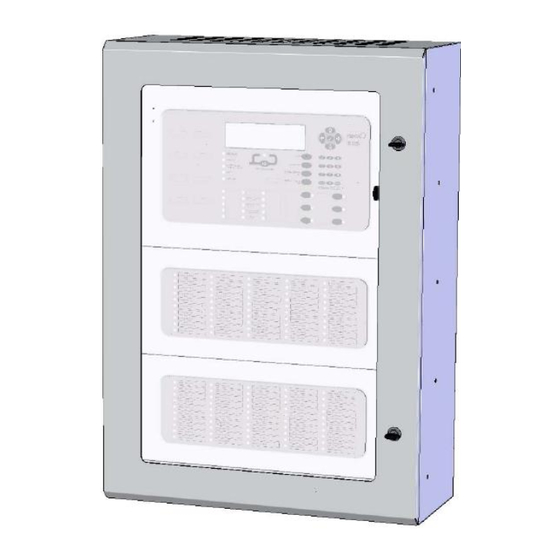
Summary of Contents for Advanced Mx-5101xR
- Page 1 5000 Series Rack Panels The operation and functions described in this manual are available from Software Version Mx5000-050-04 onwards. www.advancedco.com...
- Page 2 Specifications & Ordering: Models, Sales Order Parts: Mx-5101xR Panel 1-LP Module 6U Mx-5201xR – Mx-5202xR Panel 2-LP Module 6U Mx-5401xR – Mx-5404xR Panel 4-LP Module 6U * Add suffix (x): N for Nittan and V for Argus Vega Mxp-514 AC Filter Card Kit...
-
Page 3: Table Of Contents
Table of Contents Page INTRODUCTION............................. 4 ............................. 4 TANDARDS ........................5 AUTIONS AND ARNINGS ............................5 ESCRIPTION 1.3.1 5000R Series ............................. 5 1.3.2 5000VR Series ........................... 5 EN54 F ............................ 5 UNCTIONS ........................6 NSTALLATION PPROVALS 1.5.1 Fire System Installations ........................6 1.5.2 Wiring Regulations .......................... -
Page 4: Introduction
1 Introduction 1.1 Standards Advanced Electronics Ltd declares that the products identified below conform to the essential requirements specified in the Construction Products Directive 89/106/EEC: 0786-CPD-20952 EN54-2: 1997 +A1:2006 Control and indicating equipment for fire detection and fire alarm systems for buildings... -
Page 5: Cautions And Warnings
The 5400VR is a Multiple Loop, Analogue Addressable Fire Alarm Control Panel with provision for up to four loops. All above models are designed for use with the Advanced (AV) fire detection devices. 1.4 EN54 Functions The EN54 functions and options with requirements are identical to standard 5000 Series Panels. Refer to the Product Manual (Document No. -
Page 6: Installation Approvals
1.5 Installation Approvals 1.5.1 Fire System Installations The panel must be installed and configured for operation in accordance with these instructions and the applicable code of practice or national standard regulations for fire systems installation (for example BS5839-1: 2002) appropriate to the country and location of the installation. 1.5.2 Wiring Regulations The panel and system must be installed in accordance with these instructions and the applicable wiring codes and regulations (for example BS7671) appropriate to the country and location of the installation. -
Page 7: Installation
2 Installation 2.1 Identification of Parts The following diagram shows the major parts of the panels for the 16U enclosure. 1U Blank Plate Back Box Control Panel Key Lock CAM Lock Glazed Outer Door 1U Blank Plate Blank Plates or Optional key lock is optional modules available... -
Page 8: Mechanical Specifications
2.2 Mechanical Specifications Item Specification Details MXM-510-16U MXM-510-20U Dimensions (H x W x D) 730 x 535 x 230 910 x 535 x 230 Weight 22 Kg 25 Kg IP Rating (Door Closed) IP55 IP55 IP Rating (Door Open) IP30 IP30 2.2.1 Enclosure –... -
Page 9: Enclosure - Other Sizes
2.2.2 Enclosure – Other Sizes Other wall mount enclosure sizes are available in height increments of 4U (178mm). Fixings point positions are adjusted accordingly. 2.2.3 Enclosure – Commercial All of the modules may be housed in any commercially available 19” rack mount enclosure (e.g. SAREL or RITTAL) . -
Page 10: Mxm-510-Cp
2.2.5.3 MXM-510-CP: A chassis plate can be fitted and secured to the rear wall using six M4 nuts and washers and utilises the same fixing points as the battery shelves. Order this item separately. If fitted, batteries must be located in the bottom of the enclosure with or without MXM-510-BS1. The chassis plate provides mounting positions for up to eight peripheral bus modules or up to six peripheral bus modules and a power supply (MXS-050 or MXS-051). -
Page 11: Modules
The Panel Module is supplied in a 6U High rack mount enclosure chassis. The depth of the back box is 125 mm. The panel module weight is 6 kg. The door is securely locked using the standard Advanced Electronics Ltd panel key. The internal arrangement of the panel module is shown in the following diagram. -
Page 12: Wiring
When the panel module is mounted in large floor standing rack enclosures, fit the MXM- MXM-534 loop card support plate as shown opposite. Remove the three screws fixing the display card and replace with the supplied pillars. Mount the plate onto the pillars and fix in place using the supplied screws. - Page 13 2.3.1.1.2 Battery The batteries must be located on the battery shelf behind the module or in the bottom of the enclosure. Fit the Mxp-501 Battery Remote Temperature Sensor to ensure that the batteries are charged at the correct voltage. Plug the Mxp-501 into the connector and route the sensor cable along with the battery leads. Use the supplied tie-wraps to tie the sensor cable to the battery leads so that the encapsulated sensor is located close to the batteries.
-
Page 14: Led Modules
2.3.2 LED Modules LED Indicator Modules are available with 50 (Column), 100 or 200 LED indicators. All Modules are 4U in height (see also 6U Utility Module for additional mounting options). Order the required LED Module and the 4U Mounting Plate separately. A Panel can support up to 250 LED indicators in total (or one 200 LED module). -
Page 15: Utility Module - 6U
The Utility Module comprises of the same metalwork assembly as the Panel Module. Alternative doors are available and must be specified separately. All doors are securely locked using the standard Advanced Electronics Ltd panel key. The weight is 4-6 kg depending on modules fitted. Back Box... - Page 16 MXP-539 MXP-539 MXP-510/MXP-554 PBUS Module PBUS Module PBUS Module 2.3.3.1.1 Modules Screw the M3 Pillars supplied with the chassis plate into the required mounting holes. Fit the module to the pillars with the supplied M3 Screws. 2.3.3.1.2 PSE The PSE modules fit directly the chassis plate and are fixed using four M3 screws. Fit the Mxs-049 to the upper four holes and fit the Mxs-050 and Mxs-051 to the outer four holes.
-
Page 17: Door Options
2.3.3.2 Door Options The following door options are available (all diagrams show the rear view of the door). Order the required door and associated metal parts separately. Mount the door to the back box and secure the hinge using the supplied M4 Nuts, Plain and Spring Washers supplied. - Page 18 2.3.3.2.4 Small Mimic Door Option This option consists of the standard 6U panel door (with aperture) and a fascia plate. The fascia plate can be drilled and screen printing for the required graphic indicator diagram. Mimic area = 350 W x 180 H Up to two Mxp-539 Input / Output Cards are required to be mounted to the chassis.
-
Page 19: Utility Module - 8U
2.3.4 Utility Module – 8U The large Utility Module is of similar construction but 8U in height. The module accommodates either the standard 6U or large 8U utility chassis plates. The weight is 5-8 kg depending on modules fitted. The main use of the large utility enclosure is for graphical mimic indicator panels. The blank plate in the door can be removed so that it can be drilled and screen printed as required for fitting of switches and LED indicators. -
Page 20: Chassis - 8U
Earth Stud AC Terminal Block 2.3.4.2 Chassis – 8U and cable (supplied with PSU module) Chassis Plate Order separately The utility chassis plate can accept the following module types: 1x PSE Module (Mxs-049, Mxs-050 or Mxs-051) and 1x Mxp-510 BMS Interface or 1x Mxp-554 ipGateway and up to 2x Mxp-539 Mimic Interface Modules 1x PSE Module (Mxs-049, Mxs-050 or Mxs-051) and Up to 4x Mxp-539 Mimic Interface Modules (Up to 192 LED and up to 64 Switches) -
Page 21: Mimic Door
2.3.4.2.1 Modules Screw the M3 Pillars supplied with the chassis plate into the required mounting holes. Fit the module to the pillars with the supplied M3 Screws. Cable clips can be inserted on the left hand side of the chassis to route and retain the LED and switch wiring. 2.3.4.2.2 PSE The PSE modules fit directly the chassis plate and are fixed using four M3 screws. -
Page 22: Ac Filter Card
2.3.5 AC Filter Card If two or more power supplies are to be installed in the panel then, to meet conducted emissions requirements of the EMC Directive, an AC Filter Card must be installed. This also benefits in that a single AC Feed is supplied to the panel with pluggable connections for each power supply. - Page 23 USER NOTES www.advancedco.com...
- Page 24 Doc Number: 680-195 Revision: Advanced Electronics Ltd Moorland Way, Cramlington, Northumberland, NE23 1WE UK First Issued: 2013-mm-dd Tel: +44 (0)1670 707 111 Fax: +44 (0)1670 707 222 Email: sales@advancedco.com Web: www.advancedco.com www.advancedco.com...
Need help?
Do you have a question about the Mx-5101xR and is the answer not in the manual?
Questions and answers