Table of Contents

Related Manuals for Advanced Quick Zone XL Series


Summary of Contents for Advanced Quick Zone XL Series
- Page 1 www.acornfiresecurity.com 4-12 Zone Conventional Control Panel Installation, Commissioning & Operating The operation and functions described in this manual are available from Software Version 4.0 onwards. www.acornfiresecurity.com...
- Page 2 www.acornfiresecurity.com DoP QuickZoneXL 2831 EN54-2: 1997 +A1:2006 Control and indicating equipment for fire detection and fire alarm systems for buildings 544b/02 Provided options: Outputs to Fire Alarm Devices Investigation Delays to Outputs Dependency on more than one alarm signal Test Condition EN54-4: 1997 +A1:2002 +A2:2006 Power supply equipment for fire detection and fire alarm systems for buildings...
- Page 3 www.acornfiresecurity.com www.acornfiresecurity.com...
-
Page 4: Table Of Contents
www.acornfiresecurity.com Table of Contents Page ABOUT THIS PANEL .............................5 PRODUCT OVERVIEW .........................5 CABINET DETAILS ..........................6 CIRCUIT BOARDS ..........................7 MAIN PCB TERMINALS ........................9 ZONE CARD TERMINALS ......................... 10 TECHNICAL SPECIFICATION ......................11 POWER SUPPLY MODULE ....................... 12 DESIGN CONSIDERATIONS ........................13 SYSTEM DESIGN &... -
Page 5: About This Panel
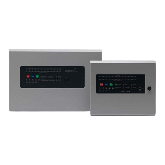
www.acornfiresecurity.com 1 ABOUT THIS PANEL 1.1 PRODUCT OVERVIEW The QuickZone XL panel is available from 4 to 12 Conventional and/or Twin Wire (sav-wire) zones. For the fire alarm engineer, the QuickZone XL has been designed to minimise labour costs by providing ample room for tasks such as wiring and changing batteries. -
Page 6: Cabinet Details
www.acornfiresecurity.com 1.2 CABINET DETAILS www.acornfiresecurity.com... -
Page 7: Circuit Boards
www.acornfiresecurity.com 1.3 CIRCUIT BOARDS QuickZone XL panels comprise of two main circuit boards plus optional ancillary boards TPCA01-X4 Master PCB TPCA03 - LED Display & Controls PCB www.acornfiresecurity.com... - Page 8 www.acornfiresecurity.com ANCILLARY CIRCUIT BOARDS QZXL-ZEC Std spec 4 zone extension card QZXL-HSZEC High spec 4 zone extension card • • 4 x conventional or Twin Wire 4 x conventional or Twin Wire zone circuits zone circuits • 2 x switched –ve outputs •...
-
Page 9: Main Pcb Terminals
www.acornfiresecurity.com 1.4 MAIN PCB TERMINALS www.acornfiresecurity.com... -
Page 10: Zone Card Terminals
www.acornfiresecurity.com 1.5 ZONE CARD TERMINALS Drawing shows the high spec version of the zone extension PCB (CZXL-HSZEC). The std version does not contain the additional outputs or sounder circuits shown at the bottom. www.acornfiresecurity.com... -
Page 11: Technical Specification
www.acornfiresecurity.com 1.6 TECHNICAL SPECIFICATION Electrical Specification Inputs & Outputs - TPCA01-X2/X4 Main PCB Terminal capacity 0.5mm to 2.5mm solid or stranded wire PSU @ output Power supply voltage control line For temperature compensation control PSU Input + - supply input. Diode protected for Max input current 3 amps. -
Page 12: Power Supply Module
www.acornfiresecurity.com 1.7 POWER SUPPLY MODULE Power Supply Specification Mains supply 230V +10% / -15% 50Hz max current 1A Mains supply fuse 4 Amp (F4A 250V) Not accessible for servicing. Internal to switch mode power unit Internal power supply rating 3.0 Amps total including battery charging Maximum load shared between outputs = 2.4A 21.27 –... -
Page 13: Design Considerations
www.acornfiresecurity.com This guide is intended as an aid to 2 DESIGN CONSIDERATIONS designers and installers of fire detection systems. It is NOT to be A few handy tips 2.1 SYSTEM DESIGN & PLANNING used as a substitute to BS5839 which should be read in full. What is a detection zone? In order to direct those responding to a fire alarm signal, particularly the fire service, to the area of a fire, all buildings, other than very small buildings, need to be divided into detection zones. -
Page 14: Cable Types & Limitations
www.acornfiresecurity.com General • Fire Alarm Control Panels should be installed at a location appropriate for staff and fire fighters • All mains supply isolators must be double pole and suitably marked • All joints to be fire resisting, junction boxes to be labelled ‘FIRE ALARM’. •... -
Page 15: General Conventional System Schematic
www.acornfiresecurity.com 2.2 GENERAL CONVENTIONAL SYSTEM SCHEMATIC www.acornfiresecurity.com www.advancedco.com... -
Page 16: General Twin Wire System Schematic
www.acornfiresecurity.com 2.3 GENERAL TWIN WIRE SYSTEM SCHEMATIC www.acornfiresecurity.com www.advancedco.com... -
Page 17: Installation
www.acornfiresecurity.com 3 INSTALLATION 3.1 SAFETY Suppliers of articles for use at work are required under section 6 of the Health and Safety at Work Act 1974 to ensure as reasonably as is practical that the article will be safe and without risk to health when properly used. An article is not regarded as properly used if it is used “without regard to any relevant information or advice”... -
Page 18: Esd Precaution
www.acornfiresecurity.com 3.2 ESD PRECAUTION Electronic components are vulnerable to damage by Electrostatic Discharges (ESD). An ESD ATTENTION OBSERVE PRECAUTIONS wrist strap, suitably grounded, should be worn at all times when handling pcbs. These wrist FOR HANDLING ELECTROSTATIC SENSITIVE DEVICES straps are designed to prevent the build-up of static charges, not only within a person’s body, but on many other materials. -
Page 19: Mains Connections
www.acornfiresecurity.com Typical panel layout Drawing shows typical internal layout of the panel cabinet with two 3.2Ah, 12v batteries fitted 3.5 MAINS CONNECTIONS Do not connect the mains supply to the panel until you are fully conversant with the layout and features of the equipment. A rating plate is attached to the power supply module describing the nature of the supply permitted. -
Page 20: Connecting The Batteries
www.acornfiresecurity.com 3.6 CONNECTING THE BATTERIES Batteries of even very small capacity are capable of delivering very high currents which can cause fire or injury, therefore battery connections should be done with caution. The panel is supplied with battery leads already connected to the battery terminals on the main PCB. These leads are coloured red for +ve and black for -ve. -
Page 21: Setup & Programming
www.acornfiresecurity.com 4 SETUP & PROGRAMMING 4.1 NETWORK PANELS SETUP The system can support up to 8 networked control panels, 1x Master and up to 7x Slaves. Comms PCB To run a network, a Comms PCB (TPCA05) must be fitted to each control panel. Any QZXL or QZXL32 panel from 4 to 32 zones with software version 4.0 and above may be used. - Page 22 www.acornfiresecurity.com Programming The Master panel will need to be programmed for the number of networked panels on the system. See Panel wide programming settings, code 2-1-2-3, option 10 (Set number of Network Slave Panels on System). Addressing Each panel needs to have a unique address. The addressing is done using the 4-way DIL switches on each of the COmms PCBs using binary code values, see diagram below.
-
Page 23: Twin Wire Mode
www.acornfiresecurity.com 4.2 TWIN WIRE MODE What is Twin Wire? Twin Wire is what is often referred to as Sav Wire. The technology enables sounders and beacons to be connected to the same circuit as the detectors and call points. This can result in greatly reduced installation time and cost. -
Page 24: Zone Interface Function
www.acornfiresecurity.com 4.3 ZONE INTERFACE FUNCTION This setting configures the last zone on the panel, (i.e. zone 4 on a 4 zone, zone 8 on an 8 zone and zone 12 on a 12 zone), to be used for interconnection from other control panels. It is possible, in the Level 3 engineering programming, to setup any zone for this function;... -
Page 25: Level 3 Engineering Options
www.acornfiresecurity.com 4.4 LEVEL 3 ENGINEERING OPTIONS A series of programmable engineering options are available. These programming modes are initiated by entering a four digit code using buttons 1 - 4 on the keypad followed by the ENTER button. To access Level 3 options, first set switch 3 on the 3 way DIL switch located on the main PCB to the ‘ON’... -
Page 26: Programming Options Index
www.acornfiresecurity.com 4.5 PROGRAMMING OPTIONS INDEX The following programmable options and settings are available. Option/Setting Description Code(s) Page View History View the last 40 events 1111 Set Fault Buzzer Volume Set the fault buzzer volume to high or low 2224 Clear All Disablements Remove all disablements which have been set for any 1121 zone, sounder circuit, output or delay... - Page 27 www.acornfiresecurity.com View History The control panel stores a log of the last 40 events which have occurred. This is useful for identifying intermittent faults or activations. Enter the above code and press ENTER, the most recent event that has occurred is displayed. Use the ENTER button to progress backwards through the indications.
- Page 28 www.acornfiresecurity.com Set Fault Buzzer Volume There are two levels of volume for the internal fault buzzer, high and low. Enter the above code and press the ENTER button to increase or decrease the fault buzzer tone from the previous level. Setting will change when ENTER button is pressed.
- Page 29 www.acornfiresecurity.com Panel Wide Settings There are 11 general, panel wide, settings available. Enter the above code and press the ENTER button. The 11 programmable options are represented by fire zone LEDs 1 - 11. Use button 1 to move to option required as per table;...
- Page 30 www.acornfiresecurity.com Press button 1 to move to next option or press and hold button 1 for 3 seconds to exit programming mode 2-1-2-3. (The panel will confirm the new access code one more time before exiting the programming mode). www.acornfiresecurity.com www.advancedco.com...
- Page 31 www.acornfiresecurity.com OPTION 2. Set Number of Repeater Panels on System If repeater panels are to be used, the quantity on the system, 1- 8, must be set up for monitoring purposes. An incorrect quantity will cause a repeater fault to be shown on the panel. With the zone 2 fire LED lit, the amber, fault LEDs will show the current quantity of repeaters set 0 - 8.
- Page 32 www.acornfiresecurity.com OPTION 4. Turn Off Battery Monitoring (EN54!) The battery monitoring may be disabled for applications where this is appropriate such as non fire alarm use or where no battery backup is required. Note: There is no remote PSU fault input is available on the QuickZone XL With the zone 4 FIRE LED lit, the amber, fault LEDs will show the current setting.
- Page 33 www.acornfiresecurity.com OPTION 6. Change Network / Repeater Comms Monitoring Type (EN54!) The network & repeater panels are designed to be wired in a fault tolerant (fail safe) loop configuration, from comms A to B and back to the main panel again (see drawing below). This enables repeater panels to still work if there is a break in the cables.
- Page 34 www.acornfiresecurity.com OPTION 7. Set Number of Output Cards Up to 2 output / relay cards may be added to each control panel to provide additional common or zonal outputs. The presence of the cards must be setup to enable operation. With the zone 7 fire LED lit, the amber, fault LEDs (zone 1 &...
- Page 35 www.acornfiresecurity.com OPTION 11. Inhibit Fire & Fault Buzzer on Network Slave Panel It is possible to inhibit the fire and/or fault buzzers of the network slave panels. This is useful if the panels are to be mounted together for a larger system. This option must be set on each individual slave panel. With the zone 11 fire LED lit press the ENTER button.
- Page 36 www.acornfiresecurity.com Zone Function Settings There are 8 functional settings available for each zone. These are as follows: Fire latching Normally a zone latches a fire input signal. This setting allows the panel to clear automatically when a fire signal is removed. This is useful for interfacing purposes. Short circuit as alarm (EN54!) For Older non EN54 or BS5839 compliant systems.
- Page 37 www.acornfiresecurity.com With the required zone for editing LED lit, press the ENTER button to enter ‘editing mode’. The fire zone 1 LED will now pulse to indicate the editing of attribute 1 (fire latching) for the selected zone. Use button 1 to scroll to the attribute that requires editing, indicated by a pulsing fire LED 1 - 9 as per table below.
- Page 38 www.acornfiresecurity.com Gate Valve Indication The gate valve open position (i.e. ready to allow water to pass through the valve in the event of a fire) is the normal default valve position and can be indicated on the panel with the red fire LED. If the gate valve is closed, the zone fault LED is illuminated.
- Page 39 www.acornfiresecurity.com Select zone(s) to be programmed for Gate Valve or Fire Pump status monitoring as per ‘Zone Function Settings’ programming mode 3-1-2-1. With the require zone for editing LED lit, press the ENTER button the enter ‘editing mode’. The fire zone 1 LED will now pulse to indicate the editing of attribute 1 (fire latching) for the selected zone. Use button 1 to scroll to pulsing fire LED 8 (gate valve &...
- Page 40 www.acornfiresecurity.com DEPENDENCY MODES Dependency modes are features described in EN54-4 for the processing of confirmation alarms. It is a requirement by some monitoring stations and local fire authorities in order to reduce the possibility of false alarms. The QuickZone XL has 3 dependency mode options, A, B & C. Only one type can be applied to the panel but any or all zones can be independently set for dependency mode.
- Page 41 www.acornfiresecurity.com Dependency Mode Selection To change the dependency mode type for the panel, enter the above code and press ENTER (panel is set to type A by default). The amber, fault / disabled / test LED 1 will pulse and the current setting will be indicated by a steady amber, fault / disabled / test LED as per table below.
- Page 42 www.acornfiresecurity.com Dependency mode Twin Wire detector compatibility If using dependency mode, QuickZone XL panels are designed to work with the following conventional detectors:- • Apollo Series 65 • Apollo Orbis • Hochiki CDX • Nittan Evolution Conventional However, if also using Twin Wire mode the panels are optimised for use with Apollo Series 65 heads & 45681- 206 Sav-Wire bases.
- Page 43 www.acornfiresecurity.com EN54 Sounder Resound Options By default, after an initial fire condition and the (blue) Silence Alarms button has been activated, any new fire condition in a different zone will cause the alarms to resound. It is possible to change this on a zonal basis so that any new alarm in a different zone will not resound the alarms.
- Page 44 www.acornfiresecurity.com Apply Delay to Outputs for Selected Zones The activation of sounder circuits and aux outputs can be delayed in response to selected zones. The actual delay time is set up in the panel wide programming options, 2-1-2-3. The setting of delays here applies to all sounder circuits, all aux outputs or all sounder circuits and all aux outputs.
- Page 45 www.acornfiresecurity.com Input Function Settings The QuickZone XL has two inputs located on the main circuit board, Class Change (CC) and Alert (PUL). Switching a negative voltage into these inputs will cause the alarm sounders to operate. The Class Change input (CC) will cause the alarms to sound continuously and the Alert input (PUL) will cause the alarms to pulse.
- Page 46 www.acornfiresecurity.com Output Programmability & Miscellaneous All of the relays & outputs on the control panel’s main circuit board (TPC-A01) have default functions, i.e. operate on fire or fault. The function for each of these outputs, however, can be changed. The outputs can also be programmed to have different responses for selected zones.
- Page 47 www.acornfiresecurity.com Relay & Output Responses to Selected Zones Each of the relays and switched -ve outputs on the main circuit board and high spec zone extension cards can be independently programmed to respond in one of three different ways for each zone, ON, OFF or PULSING. NOTE: Before any programming can be applied to the outputs on the main circuit board, they must first be made programmable using code 4-1-4-2.
- Page 48 www.acornfiresecurity.com Conventional Sounder Circuit Responses to Selected Zones Each of the conventional sounder circuits on the main circuit board and high spec zone extension cards can be independently programmed to respond in one of three different ways for each zone, ON, OFF or PULSING. Enter the above code and press the ENTER button.
- Page 49 www.acornfiresecurity.com Twin Wire Sounder Circuit Responses to Selected Zones If using Twin Wire zones the sounders on each of the Twin Wire circuits can be programmed to respond to each Twin Wire zone in the same way as the conventional sounder circuits. The process is exactly the same as with the conventional sounder circuits, but using the above code.
- Page 50 www.acornfiresecurity.com Relay & Output Functional Options Each of the relays and switched -ve outputs on the main circuit board and high spec zone extension cards can be independently programmed with a custom response to; Silence Alarms (including, Silence button or input programmed for remote Silence Alarms), Evacuate (including, Resound button, input programmed for Evacuate or 220O ‘Evacuate’...
- Page 51 www.acornfiresecurity.com When finished, press and hold Button 1 for 3 seconds to save setting and exit programming mode. Twin Wire Sounder Circuit Functional Options If using Twin Wire zones, the sounders on each of the Twin Wire circuits can be programmed with a custom response to various panel functions in the same way as the relays and switched -ve outputs.
- Page 52 www.acornfiresecurity.com www.acornfiresecurity.com www.advancedco.com...
- Page 53 www.acornfiresecurity.com Output Relay Network Responses The Fire relays and switched negative outputs in the panel will, by default, activate continuously for any fire condition from the entire network. The Fault relay and other switched negative outputs will also activate continuously, by default, if they have been made programmable using programming option 4-1-4-2.
- Page 54 www.acornfiresecurity.com Sounder Circuit Network Responses The six possible sounder circuits in the panel will, by default, activate continuously for any fire condition from the entire network. This option enables the default to be changed for each of the local circuits. The response can be either; CONTINUOUS, PULSING or NONE when a fire condition is received from any other panel in the network.
- Page 55 www.acornfiresecurity.com Comms PCB Output Functional Options If a repeater Comms PCB (TPCA05) has been fitted to the panel, the 6, swtched -ve outputs on the PCB can also be independently programmed with a custom response to; Silence Alarms (including, Silence button or input programmed for remote Silence Alarms), Evacuate (including, Resound button, input programmed for Evacuate or 220Ω...
- Page 56 www.acornfiresecurity.com System Diagnostics Mode System faults can occur if a PCB in the control panel or one of the repeater panels stops working. This may be due to a fault condition, loss of power, software lockup or memory checksum error. A system fault can also occur if the internal PCB configuration or number of repeater panels has not been correctly set up in the panel wide programming options (2-1-2-3).
- Page 57 www.acornfiresecurity.com REPEATER PANEL SETUP & PROGRAMMING The QuickZone XL can support up to 8, fully functional repeater panels on the network which can be either the 12-way repeater panels or Remote Display Units or a combination of both. N.B. The 12-way repeater panel will only display the first 12 zone of any network system.
- Page 58 www.acornfiresecurity.com Network System Note: Repeater panel addresses are parallel to network slave panel addresses on a network system. i.e. a repeater and a network slave panel can both have address 01 on the network. www.acornfiresecurity.com www.advancedco.com...
- Page 59 www.acornfiresecurity.com Wiring The repeater panels are designed to be wired in a fault tolerant (fail safe) loop configuration, from comms A to B and back to the main panel again (see diagram). This enables repeater panels to still work if there is a break in the cables.
-
Page 60: Operating
www.acornfiresecurity.com 5 OPERATING 5.1 PANEL CONTROLS & INDICATIONS Activate Controls In normal standby mode the keypad controls are inactive to protect from unauthorised operation. Controls can be activated by using the ‘Activate Controls’ key switch or by entering a four digit code using the keypad. The use of a code entry to activate the controls is enabled by default but can be disabled in the Level 3 engineering functions. -
Page 61: Status Led Indicators
www.acornfiresecurity.com 5.1.1 Status LED Indicators LED On LED Pulsing Zones in Fire 1 - 12 Indicates alarm condition in zone. Zone Fault/Disabled/Test Indicates zone circuit is disabled or in test Indicates a fault in the zone circuit mode 1 - 12 Supply Healthy: Indicates mains and/or battery supply is present... -
Page 62: Disable Mode
www.acornfiresecurity.com 5.2 DISABLE MODE Disable Mode is used to disable or isolate individual zone circuits or all sounder circuits or all auxiliary outputs. To initialise Disable Mode, firstly activate the controls by turning the key switch or by entering the four digit code. Then press and hold the Disable Mode button (1) for 3 seconds. -
Page 63: Test Mode
www.acornfiresecurity.com 5.3 TEST MODE Test Mode is used when testing the fire alarm system. In test mode the devices in the zone(s) in test, detectors and call points etc., can be activated and the panel will automatically reset, enabling the system to be tested by one person. -
Page 64: Fault Diagnosis
www.acornfiresecurity.com 5.4 FAULT DIAGNOSIS If the panel has detected a fault on the system, the General Fault LED will be illuminated and the internal fault buzzer will sound. Secondary LEDs will also be illuminated depending on the location of the fault. Pressing and holding the ENTER button will reveal more detailed information about the location and type of fault. -
Page 65: Functionality During A System Fault
www.acornfiresecurity.com 5.5 FUNCTIONALITY DURING A SYSTEM FAULT A system fault is indicated when a processor controlling a function in the panel has a watchdog time out or processor failure. In the event of a system fault the particular board affected may not be functional. The following indications may be observed. -
Page 66: Service & Maintenance
www.acornfiresecurity.com 6 SERVICE & MAINTENANCE The following section is a summary of the requirements in BS5839 Part 1 For comprehensive information a copy of BS5839 Part 1 can be purchased from the British Standards Institution via their web site at www.bsi-global.com. 6.1 THE NEED FOR MAINTENANCE Your Fire Alarm System is working 24 hours a day, 365 days a year. - Page 67 www.acornfiresecurity.com WEEKLY TEST The call point test key should be inserted firmly and deliberately into the bottom of the manual call point. Once activated it may be necessary to wait up to four seconds before the alarms sound. Your manual call points may not be the same as the ones described above. If not please refer to your service and maintenance company for instructions.
-
Page 68: Periodic Inspection & Servicing
www.acornfiresecurity.com 6.4 PERIODIC INSPECTION & SERVICING Inspection & servicing should only be carried out by a ‘Competent Person’ who has sufficient knowledge to check the whole system. This would normally be a qualified electrical contractor or fire alarm specialist. Inspection & servicing visits are normally conducted on a quarterly basis unless such factors as a dirty environment warrant servicing on a more regular basis. -
Page 69: Schedule Of Testing Log Book
www.acornfiresecurity.com 6.4.1 SCHEDULE OF TESTING LOG BOOK This Section is to be used to record ALL Weekly Tests of The Fire Alarm System DATE & DEVICE TESTED & COMMENTS INITIALS OF LOCATION TESTER (IF ANY) TIME OF TEST www.acornfiresecurity.com www.advancedco.com... - Page 70 www.acornfiresecurity.com SCHEDULE OF TESTING This Section is to be used to record ALL Weekly Tests of The Fire Alarm System DATE & DEVICE TESTED & COMMENTS INITIALS OF LOCATION TESTER (IF ANY) TIME OF TEST www.acornfiresecurity.com www.advancedco.com...
- Page 71 www.acornfiresecurity.com SCHEDULE OF TESTING This Section is to be used to record ALL Weekly Tests of The Fire Alarm System DATE & DEVICE TESTED & COMMENTS INITIALS OF LOCATION TESTER (IF ANY) TIME OF TEST www.acornfiresecurity.com www.advancedco.com...
- Page 72 www.acornfiresecurity.com SCHEDULE OF TESTING This Section is to be used to record ALL Weekly Tests of The Fire Alarm System DATE & DEVICE TESTED & COMMENTS INITIALS OF LOCATION TESTER (IF ANY) TIME OF TEST www.acornfiresecurity.com www.advancedco.com...
-
Page 73: False Alarms, Faults & Engineers Visit
www.acornfiresecurity.com 6.4.2 FALSE ALARMS, FAULTS & ENGINEERS VISIT Fault / Reason for Action taken Date Work Completed Engineers Details Call-Out www.acornfiresecurity.com www.advancedco.com... - Page 74 www.acornfiresecurity.com FALSE ALARMS, FAULTS & ENGINEER VISITS Fault / Reason for Action taken Date Work Completed Engineers Details Call-Out www.acornfiresecurity.com www.advancedco.com...
- Page 75 www.acornfiresecurity.com FALSE ALARMS, FAULTS & ENGINEER VISITS Fault / Reason for Action taken Date Work Completed Engineers Details Call-Out www.acornfiresecurity.com www.advancedco.com...
- Page 76 www.acornfiresecurity.com FALSE ALARMS, FAULTS & ENGINEER VISITS Fault / Reason for Action taken Date Work Completed Engineers Details Call-Out www.acornfiresecurity.com www.advancedco.com...
- Page 77 www.acornfiresecurity.com USER INSTRUCTIONS If an alarm condition is present YOU MUST FOLLOW YOUR NORMAL FIRE DRILL PROCEDURES. A responsible person should then:- Check the control panel to see which area or zone has caused the system to go into alarm. This will be indicated by a pulsing red LED on the front of the control panel.
- Page 78 www.acornfiresecurity.com This page is intentionally left blank. www.acornfiresecurity.com www.advancedco.com...
- Page 79 www.acornfiresecurity.com USER NOTES www.acornfiresecurity.com www.advancedco.com...
- Page 80 Advanced Electronics Ltd The Bridges, Balliol Business Park, Newcastle upon Tyne, NE12 8EW. UK Doc Number: 680-216 Tel: +44 (0)345 894 7000 Revision: Email: sales@advancedco.com Web: www.advancedco.com www.acornfiresecurity.com www.advancedco.com...
Need help?
Do you have a question about the Quick Zone XL Series and is the answer not in the manual?
Questions and answers