
Subscribe to Our Youtube Channel
Related Manuals for Advanced LIFELINE Px-100


Summary of Contents for Advanced LIFELINE Px-100
- Page 1 Paging Control Product Manual The operation and functions described in this manual are available from Software Version PX100-001-00 onwards. www.advancedco.com...
- Page 2 Item Specification Details Enclosure Steel IP30 RAL7035 Dimensions H x W 288 x 348 x 78 x D mm Weight (excluding 3.9Kg batteries) Temperature -5°C to 40°C Humidity (RH) 95% Max Cable Entries 6x top / 4x bottom / 1x rear (20mm knockouts) AC Supply 230V AC +/- 15%, xxA...
-
Page 3: Table Of Contents
Table of Contents Page INTRODUCTION............................. 5 ............................. 5 TANDARDS ........................5 AUTIONS AND ARNINGS ............................6 ESCRIPTION 1.3.1 Px-100 Series............................. 6 ........................6 NSTALLATION PPROVALS 1.4.1 Fire System Installations ........................6 1.4.2 Wiring Regulations ..........................6 1.4.3 Radio Licence ............................ 6 OPERATION .............................. - Page 4 4.2.2 Message Buttons ..........................25 4.2.3 Inputs .............................. 25 4.2.3.1 Input Text .............................. 25 4.2.3.2 Action ..............................26 4.2.3.3 Monitored .............................. 26 4.2.3.4 Type: ..............................26 4.2.3.5 Pager Group: ............................26 4.2.3.6 Trigger SleepCom ..........................26 4.2.4 Outputs ............................27 4.2.4.1 Mode ..............................
-
Page 5: Introduction
1 Introduction 1.1 Standards Advanced Electronics Ltd declares that the product identified below conforms to the essential requirements specified in the RTTE Directive 1999/5/EC: On-site paging EN 300 224-2 ERM On-Site Paging EN 301 489-2 ERM EMC Radio Paging Equipment Px-100 This product is of the Equipment Type “Class 2”... -
Page 6: Description
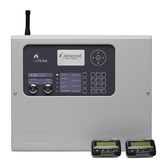
Refer to the User Manual (Document No. 680-191) for a quick guide to operation. 1.3.1 Px-100 Series The LIFELINE Px-100 is a Control Panel for communication of alarm, fault, test and other conditions to hand held or fixed paging receivers for the purpose of communicating those conditions to persons with deafness or hard of hearing. -
Page 7: Operation
2 Operation Display Navigation Buttons D E F A B C G H I J K L M N O P Q R S T U V W X Y Z E S C M E N U Status Indicators Function Buttons Number Buttons 2.1 Controls and Indications... -
Page 8: Function Buttons
2.1.3 Function Buttons The following table contains a list of all of the control button functions available. Button Description Access Level Function Button Level-1 or Level-2 Programmable message function – the function will Depends on be identified on slide-in label text. Programming Press to send the programmed message. -
Page 9: Key Switches
2.1.7 Key Switches The key switches are used to enable access to the system and to configure the system to operating modes. Switch Operation 2-Position: Enables user controls and Level-2 access – key is ACCESS L003 trapped in the enable position. (Controls) MODE 3-Position: Enables test and engineer modes in addition to... -
Page 10: User Functions
2.3 User Functions Operating Modes – The panel has three basic operating modes selected by the position of the front panel key- switch (or by menu option). Normal Mode The normal (quiescent) display is shown opposite. The display will show events and other information as required. - Page 11 Fault Conditions [System Status] If the panel detects a fault condition, the 1 of 1 conditions: details are shown on the display. The Fault INPUT 8 LED will flash. OPEN CIRCUIT As with all transmissions, the display will LAST MESSAGE SENT… also show the text of the last transmitted FAULT >INPUT 8 >OPEN message for 30 sec after the last key press.
-
Page 12: Level 1 Menu Options
2.3.1 Level 1 Menu Options Press the MENU button. [Level 1 Menu] The Level 1 menu shows three options. ENABLE CONTROLS VIEW LED TEST Use the buttons to select the required option. Press the ✔ button to select. 2.3.1.1 Enable Controls Enable controls is normally activated using the front panel key-switch. -
Page 13: Led Test
[Panel Levels] In addition to the parameters opposite, the SYSTEM VOLTS 13.31V transmitter current is available. This is BATTERY (V) 13.52V shown in milliamps. CHARGER (V) 13.94V CHARGER (I) 322mA TEMPERATURE 25deg Use the buttons to scroll through the readings. Press ESC to return to the previous menu. -
Page 14: Operating Mode
This option will activate the internal buzzer for five (5) seconds. 2.3.2.3 OPERATING MODE Operate Test Engineer This function is normally activated using the front panel key-switch. Insert the key and turn anti-clockwise or clockwise to select the test or engineers mode as required. The key can only be removed in the normal operating mode. -
Page 15: Installation
3 Installation 3.1 Identification of Parts The following diagram shows the major parts of the panel. The Px-100 comprises of a back box, chassis plate electronic assembly, aerial assembly and a cover. The chassis plate is fixed to the back box with two screws. The cover is fixed to the back box with two hex (Allen) key screws. -
Page 16: Removing The Chassis
3.2.2 Removing the Chassis It is recommended that the chassis be removed before fitting the panel to the wall. To remove the chassis: Disconnect the earth cable connecting the chassis to the spade terminal on the rear enclosure. Remove the two screws holding the chassis to the back box and carefully remove the chassis from the rear enclosure. -
Page 17: Recommended Cable Routing Arrangement
3.2.5 Recommended Cable Routing Arrangement It is recommended that the typical routing arrangement shown in the diagrams AC MAINS opposite be employed. INPUT / OUTPUT SIGNALS Alternative entry in back Segregate the low voltage of box wiring (DC Power and Field Wiring) from any AC Mains Wiring. -
Page 18: Wiring Installation
3.3 Wiring Installation All electrical wiring installation work should be carried out in accordance with the code of practice or applicable national standards appropriate to the country of installation. To maintain electrical integrity of the SELV wiring on the DC Power and communications lines all SELV wiring should be segregated from the LV mains wiring and be wired using cable with insulation suitable for the application. -
Page 19: Battery Installation
3.3.2 Battery Installation The panel requires a single 12V battery for standby operation. The battery leads are connected onto the base card via a plug, as shown in the diagram opposite. Refer to the Specifications for minimum and maximum battery sizes allowed. -
Page 20: Switch Inputs
Connect RX input to panel TX output Connect GND to panel GND can be used. Cable size: 28-16AWG (0.1mm -1.5mm This interface can be used for serial connection to Base Card Connections. the Mx range of fire alarm control systems offered by Advanced Electronics Ltd. www.advancedco.com... -
Page 21: Rs485 Interface
This interface can be used for serial connection to the Mx range of fire alarm control systems offered Base Card Connections. by Advanced Electronics Ltd. 3.3.7 USB Interface The Px-100 is equipped with a USB I/F Circuit. This can be used for connection to a PC for use with the PC Tools. -
Page 22: Programming
4 Programming 4.1 Introduction 4.1.1 Access Levels The panel operation is protected from inadvertent and erroneous misuse by means of four access levels. These levels are as follows: Level 1 Untrained user Level 2 Authorised User Level 3 Commissioning, Service and Maintenance Level 4 Commissioning, Service and Maintenance –... -
Page 23: Changing Text Descriptions
To change the text description, first highlight the text description within the appropriate programming option and then press the ✔ button. The display then changes to show the text entry dialogue screen. For example: KEY IN TEXT >ADVANCED SITE 2 < pqrs... -
Page 24: Level 3 Menu Functions
[General Text] The menu shows three configurable items. PANEL NAME: ADVANCED SITE 2 TEST TEXT: TEST FAULT TEXT: FAULT Use the buttons to highlight the required text item and then press the ✔ button to select it. -
Page 25: Message Buttons
4.2.2 Message Buttons This menu allows the configuration of the text message to be transmitted when the button is pressed, whether the button is operative at Level-1 and/or Level-2 and whether this button will be used to trigger a SleepCom unit associated with the system. -
Page 26: Action
4.2.3.2 Action To change the action, press the ✔ button and a further menu with options is shown. [Input Action] ↓ The menu shows the input actions available. NOT IN USE TRANSMIT –ONCE TRANSMIT – REPEAT TEST MODE TEST OVERRIDE The following input actions are possible: Action Function... -
Page 27: Outputs
4.2.4 Outputs This menu allows the outputs to be configured. [Prog. Outputs] The menu shows the output modes available. RELAY 1: ANY INPUT ON RELAY 2: GENERAL FAULT RELAY 3: Use the buttons to highlight the required output and then press the ✔ button to select it. [Output Settings] The menu shows the output settings available. -
Page 28: Tools
4.2.5 Tools This menu allows the basic transmitter functionality to be tested and configured. [Tools Menu] The menu shows the options available for WALK TEST testing and configuring the transmitter. SEND TEST MESSAGE TRANSMITTER POWER 4.2.5.1 Walk test This menu allows a walk-test to be controlled from the level-3 menu. Activates a special sequence which transmits a test message repeatedly (time interval dependant on configuration) to allow a one-man walk test of the building to assist in ascertaining reception coverage. -
Page 29: Passwords
Use the buttons to highlight the required power level and then press the ✔ button to select it. Refer to the Site Survey section for the procedure and tools / settings required to undertake the task of surveying the site and commissioning the panel for optimal transmitter power / reception. 4.2.6 Passwords This menu allows the four user passwords and the engineering password to be adjusted. -
Page 30: Out Of Range
This parameter is used to denote which of the 2 serial communication ports is in use. The options are RS-232 or RS-485. The LifeLine panel may be connected to an Mx Fire System (Advanced Electronics Ltd) via a serial link. This link may take the form of an RS-232 or RX-485 standard – normally the RS-232 port will be used to connect directly to an MXP-047 interface unit. -
Page 31: Program
4.2.7.10 Program The display shows the current version of software installed in the panel. The operating program is protected by a method using a checksum. A fault condition will be indicated if the memory contents have altered such that the checksum is incorrect. Press the button to show the checksum [Program Checksum] The checksum value will depend on the version... -
Page 32: Serial Messages And Pager Groups
4.2.10.2 Serial Messages and Pager Groups Using the MXP-047 Interface unit, a similar Pager Group configuration can be realised for a serial connection to an MX Fire System. In this case the ‘Address’ parameter associated with the ‘Pager Zones’ edit screen of the MXP-047 configuration tool relate directly to the Pager Group designations of the LifeLine control panel. -
Page 33: Service And Maintenance
5 Service and Maintenance 5.1 Maintenance Schedule This equipment should be maintained in accordance with the regulations and codes appropriate to the country and location of installation. The following is recommended if no other regulations apply. 5.1.1 Daily Actions The site operator / user should perform the following checks and actions: a) The panel indicates normal operation. -
Page 34: Replacement Of Components
5.2 Replacement of Components In general, all of the components parts used in the construction of the panel have been selected for long life and reliability. However, certain components may require to be changed on a regular service basis. The details of these are as follows: 5.2.1 Liquid Crystal Display Expected Life:... -
Page 35: Spares
5.2.3 Spares Part Number Description PXS-001 Px-100 Chassis Assembly PXS-002 Px-100 Back Box Assembly PXS-003 PX-100 Cover Assembly PXS-004 PX-100 Antenna EXP-005 Switch End-of-Line Module (Pack of 5) For all other items, please refer to the sales part list for the sales item part number. www.advancedco.com... -
Page 36: Site Survey
5.3 Site Survey The procedure outlined in this section details how to perform either an initial or an on-going site survey to configure the optimal transmitter power setting. The objective is to minimise the power setting to prevent excessive interference spread outside the building whilst maintaining reception at all required locations in the building. -
Page 37: Appendices
6 Appendices 6.1 Appendix 1 – Forgotten Level 3 Password Should the Level-3 password be forgotten, contact Customer Support to obtain a temporary permit number to regain access to the panel programming functions. Customer Support will require a decryption key displayed by the panel. To obtain this number, attempt to gain access to the Level-3 Programming Functions entering “1”... -
Page 38: Appendix 2 - Recommended Fire Rated Cables
6.2 Appendix 2 – Recommended Fire Rated Cables The following table provides a list of suitable fire rated cables with standard (30 minute) and enhanced (120 minute) classification. Refer to Document No. 680-088 for an up to date list. Core Sizes (mm) 5839-1 Rated Manufacturer Cable Type... -
Page 39: Appendix 3 - Site Configuration Record
6.3 Appendix 3 – Site Configuration Record 6.3.1 Site Pagers and Pager Group Allocation 1. Determine how many different User Groups are required for the system. Consider how many groups of users there are requiring different types of message. Example Site Pager Record Site Pager Record User Group User Group... -
Page 40: Px-100 Configuration Record
3. Assign which Pager Groups each of the User Group pagers will respond to. Note that a maximum of 4 Pager Groups can be assigned, if this limit causes difficulty consider whether any Message Types can be combined. Example Pager Configuration Site Pager Configuration Pager Group Pager Group... -
Page 41: Message Buttons
6.3.2.2 Message Buttons Button Pager Access Level (1/2) Sleepcom Group (1-12) 1 / 2 Y / N 1 / 2 Y / N 1 / 2 Y / N 1 / 2 Y / N 6.3.2.3 Outputs Relay Mode (Tick One) Inverted? Y / N Y / N... -
Page 42: Inputs
6.3.2.4 Inputs Input Pager Action (Tick One) Monitored? Normally Sleep- Group Closed? com? (1-12) Note: Text, Pager Group, Monitored & SleepCom input settings are only relevant when the action is configured as “Transmit – Once” or “Transmit – Repeat”. 6.3.2.5 Transmitter Power Transmitter Power setting (Tick One) 25mW 50mW... -
Page 43: Appendix 4 - Slide-In Template
6.4 Appendix 4 – Slide-In Template An electronic editable version (Word™) of the template can be dowloaded from the website – see www.advel.co.uk. If required, use the default slide-in label or write in the required text on the second label. ... - Page 44 This page is intentionally left blank www.advancedco.com...
- Page 45 This page is intentionally left blank www.advancedco.com...
- Page 46 This page is intentionally left blank www.advancedco.com...
- Page 47 USER NOTES www.advancedco.com...
- Page 48 Doc Number: 680-190 Revision: 01 Advanced Electronics Ltd First Issued: 2013-mm-dd Moorland Way, Cramlington, Northumberland, NE23 1WE UK Tel: +44 (0)1670 707 111 Fax: +44 (0)1670 707 222 Email: sales@advancedco.com Web: www.advancedco.com www.advancedco.com...
Need help?
Do you have a question about the LIFELINE Px-100 and is the answer not in the manual?
Questions and answers