Table of Contents
Advertisement
Quick Links
INSTRUCTION LEAFLET IL15466
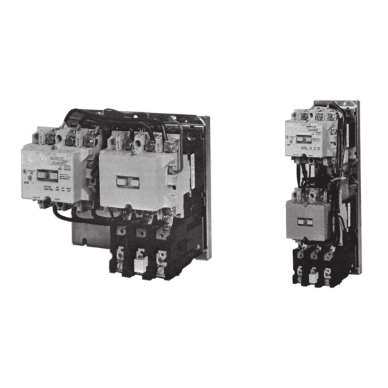
Instructions for A210, A250
Size 3 or 4 Reversing Motor Controller
THE CONTROLLER
An A210 or A250 motor controller, when wired as shown in the
appropriate connection diagram will operate as a full voltage starter and
will give protection against overload, but not against short circuit currents,
when wired and provided with overload relay (OLR) heaters as listed
in heater selection tables or when used with any means of inherent
protection activated by motor temperature.
The controller should be protected against short circuits by providing
branch circuit protection not to exceed the maximum protective device
ratings listed in Table II.
This industrial type control is designed to be installed, operated, and
maintained by adequately trained workmen. These instructions do not
cover all details, variations, or combinations of the equipment, its storage,
delivery, installation, check out, safe operation, or maintenance. Care
must be exercised to comply with local, state, and national regulations,
as well as safety practices, for this class of equipment.
Effective MAY 2011
Supersedes MARCH 1989
AUXILIARY CONTACTS - L56
(RATED B600)
Two L56's, each with one normally open pole
and one normally closed pole, are supplied as
the holding circuit auxiliary and electrical interlock
between the two coil circuits. A maximum of three
L56 auxiliary units can be installed in the recesses
of each contactor. These may be mounted with
the terminals in line with the power poles or may
be mounted with the terminals in a right angle
relationship to the power poles. They mount by
means of a spring clip which snaps into locations
provided in the motor controller unit. To remove the
L56 disengage the top spring clip, by pressing on
the extended tab, and withdraw the unit.
Advertisement
Table of Contents

Related Manuals for Eaton A210


Summary of Contents for Eaton A210
- Page 1 AUXILIARY CONTACTS - L56 THE CONTROLLER (RATED B600) An A210 or A250 motor controller, when wired as shown in the appropriate connection diagram will operate as a full voltage starter and Two L56’s, each with one normally open pole will give protection against overload, but not against short circuit currents,...
- Page 2 INSTRUCTION LEAFLET IL15466 Instructions for A210, A250 Size 3 or 4 Reversing Motor Controller Effective May 2011 EATON CORPORATION www.eaton.com...
- Page 3 INSTRUCTION LEAFLET IL15466 Instructions for A210, A250 Size 3 or 4 Reversing Effective May 2011 Motor Controller EATON CORPORATION www.eaton.com...
- Page 4 INSTRUCTION LEAFLET IL15466 Instructions for A210, A250 Size 3 or 4 Reversing Motor Controller Effective May 2011 EATON CORPORATION www.eaton.com...
- Page 5 INSTRUCTION LEAFLET IL15466 Instructions for A210, A250 Size 3 or 4 Reversing Effective May 2011 Motor Controller EATON CORPORATION www.eaton.com...
- Page 6 INSTRUCTION LEAFLET IL15466 Instructions for A210, A250 Size 3 or 4 Reversing Motor Controller Effective May 2011 MAINTENANCE - First Turn Off Power (10) located to the immediate left and right of the arc box. Remove connector straps to the overload relay. Pull the loosened upper base To Inspect Contacts structure (9) forward.
Need help?
Do you have a question about the A210 and is the answer not in the manual?
Questions and answers