Advertisement
Quick Links
INSTRUCTION LEAFLET IL17053
Instructions for A201, A211, A251
Size 6, 2 and 3 Pole Contactors,
Nonreversing or Reversing
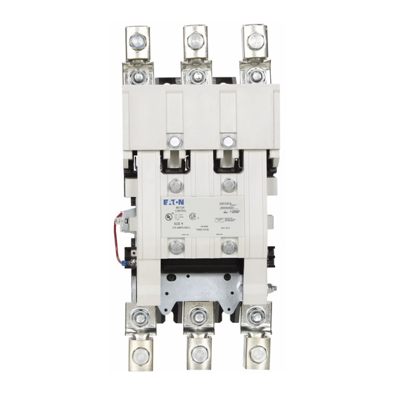
THE CONTACTOR
A201 contactors are designed for the control of inductive or non-
inductive loads at voltages between 120 and 600, AC. The units are
suitable for mounting on either steel or insulated panels. All parts are
front removable.Contactors should be protected against short circuits by
branch circuit protective devices selected in accordance with the National
Electrical Code (NEC).
This motor controller is suitable for use on a circuit capable of delivering
not more than the current (rms symmetrical amperes) shown below in
circuits rated not more than the voltage shown in Table I.
INSTALLATION
This industrial type control is designed to be installed, operated, and
maintained by adequately trained workmen. These instructions do not
cover all details, variations, or combinations of the equipment, its storage,
delivery, installation, check out, safe operation, or maintenance. Care
must be exercised to comply with local, state, and national regulations,
as well as safety practices, for this type of equipment. See page 5 for
mounting dimensions and terminal information.
Mount the contactor on a vertical surface with the line terminals above
the load terminals. Once installed, the assembly should be checked
to ensure proper operation of the basic contactor mechanism and
accessory devices before power is applied.
Effective MAY 2011
Supersedes JUNE 1989
The following list and the MAINTENANCE
instructions
a) The crossbar and springs must operate freely.
b) Auxiliary contacts and mechanical interlocks
must be properly installed and adjusted.
c) The proper operating coil must be installed and
properly connected.
d) The crossbar must be in position. The contactor
will not operate if the crossbar is rotated forward,
out of position.
e) The arc box must be in place. The contactor
must never be operated in a power circuit unless
the arc box is securely bolted in place.
f) The main contacts must have overtraveI and
spring force and move freely.
should be used as a guide:
Advertisement

Related Manuals for Eaton A201


Summary of Contents for Eaton A201
- Page 1 THE CONTACTOR A201 contactors are designed for the control of inductive or non- inductive loads at voltages between 120 and 600, AC. The units are suitable for mounting on either steel or insulated panels. All parts are front removable.Contactors should be protected against short circuits by...
- Page 2 INSTRUCTION LEAFLET IL170053 Instructions for A201, A211, A251 Size 6, 2 and 3 Pole Contactors, Effective May 2011 Nonreversing or Reversing EATON CORPORATION www.eaton.com...
- Page 3 Instructions for A201, A211, A251 Size 6, 2 and 3 Pole Contactors, INSTRUCTION LEAFLET IL17053 Effective May 2011 Nonreversing or Reversing EATON CORPORATION www.eaton.com...
- Page 4 INSTRUCTION LEAFLET IL170053 Instructions for A201, A211, A251 Size 6, 2 and 3 Pole Contactors, Effective May 2011 Nonreversing or Reversing EATON CORPORATION www.eaton.com...
- Page 5 Instructions for A201, A211, A251 Size 6, 2 and 3 Pole Contactors, INSTRUCTION LEAFLET IL17053 Effective May 2011 Nonreversing or Reversing EATON CORPORATION www.eaton.com...
- Page 6 INSTRUCTION LEAFLET IL17053 Instructions for A201, A211, A251 Size 6, 2 and 3 Pole Contactors, Nonreversing or Reversing Effective May 2011 Eaton Corporation Electrical Sector 1111 Superior Ave. Cleveland, OH 44114 United States 877-ETN-CARE (877-386-2273) Eaton.com © 2011 Eaton Corporation...
Need help?
Do you have a question about the A201 and is the answer not in the manual?
Questions and answers