Table of Contents
Advertisement
Quick Links
Instruction Leaflet IL16958
A200 Size 00, 0, 1 3 Pole Motor Controller
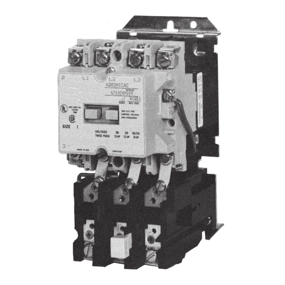
Figure 1. Size 1 A 200 Controller
THE CONTROLLER
The A200 motor controller, when wired as shown in Figure
6 or 7 , will operate as a full voltage starter and will give
protection against overload, but not against short circuit
currents, when wired and provided with overload relay (OlR)
Heaters as listed in heater selection tables or when used
with any means of inherent protection activated by motor
temperature.
The controller should be protected against short circuits by
providing branch circuit protection not to exceed the maximum
protective device ratings listed in Table II.
This industrial type control is designed to be installed, perated,
and maintained by adequately trained work-men. These
instructions do not cover all details, variations, or combinations
of the equipment, its storage, delivery, installation, check out,
safe operation, or maintenance. Care must be exercised to
comply with local, state, and national regulations, as well as
safety practices, for this class of equipment.
Effective May 2011
Supersedes August 1992
Figure 2. Dimension Drawings (Dim. in inches)
AUXILIARY CONTACTS - TYPE J
One normally-open pole adjacent to the power poles is
supplied as the holding circuit auxiliary. A maximum of four
Type J auxiliary units can be installed in the recesses of
each contactor. These may be mounted with the terminals
in line with the power poles or may be mounted with the
terminals in a right angle relationship to the power poles.
Auxiliary contacts mount by means of a spring clip and
retainer screw.
Advertisement
Table of Contents

Related Manuals for Eaton A200


Summary of Contents for Eaton A200
- Page 1 Figure 1. Size 1 A 200 Controller THE CONTROLLER The A200 motor controller, when wired as shown in Figure 6 or 7 , will operate as a full voltage starter and will give protection against overload, but not against short circuit...
- Page 2 TYPE A OVERLOAD RELAY (See Figure 4) To remove the unit rotate the retainer screw several times The A200 motor controller can be equipped with a Type A block type (counterclockwise) and then slide the auxiliary contact unit out of non-ambient compensated overload relay (unmarked and with red the recess.
- Page 3 Instruction Leaflet IL16958 For A200 Size 00, 0, 1 Effective May 2011 3 Pole Motor Controller Heaters should be selected on the basis of the actual full load WARNING: current and service factor as shown on the motor nameplate or in the manufacturer’s published literature.
- Page 4 3 Pole Motor Controller COIL The A200 motor controller is available with a single or dual voltage coil. When equipped with a single voltage coil. the contactor is wired as shown in Figures 6 and 7 . A connection diagram for a dual voltage coil is shown in Figure 5.
- Page 5 Instruction Leaflet IL16958 For A200 Size 00, 0, 1 Effective May 2011 3 Pole Motor Controller Figure 8. Control Station Connection Diagram SHORT - CIRCUIT WITHSTAND shown below in circuits rated not more than the voltage shown This motor controller is suitable for use on a circuit capable of below (Table V).
- Page 6 1111 Superior Ave. Cleveland, OH 44114 United States 877-ETN-CARE (877-386-2273) Eaton.com © 2011 Eaton Corporation Eaton is a registered trademark of Eaton All Rights Reserved Corporation. Publication No. IL16958 / 001 May 2011 All other trademarks are property of their...
Need help?
Do you have a question about the A200 and is the answer not in the manual?
Questions and answers