Table of Contents
Advertisement
Quick Links
Advertisement
Table of Contents

Subscribe to Our Youtube Channel
Related Manuals for Rish Eine NX


Summary of Contents for Rish Eine NX
- Page 1 OPERATING MANUAL Rish Eine NX 1 Phase DMAN-00IM-1047 Rev_B 11/2023...
-
Page 2: Table Of Contents
Rish Eine NX PROGRAMMABLE DPM AC Volt Meter ( 1Φ ) : DPM - V AC Ammeter ( 1Φ ) : DPM - A Installation & Operating Instructions Section Contents Introduction Measurement Reading Screens Programming 3.1 Set Up Screens Installation 4.1 EMC Installation Requirements... -
Page 3: Introduction
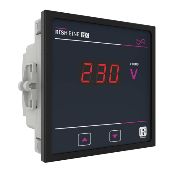
1. Introduction The DPM Series is a panel mounted 96 x 96mm Digital Panel Meters for the measurement of AC Voltage and current in three phase or single phase systems. The instrument integrates accurate measurement technology. The parameters are displayed with Ultra high brightness LED display with 14mm Digit height which enables to take readings from long distance. - Page 4 Press UP and DOWN key simultaneously to enter into setup menu The meter shows only relevant setup screens according meter model START...
-
Page 5: Programming
3. Programming The following sections comprise step by step procedures for configuring the DPM for individual user requirements. To access the set-up screens touch and hold the “ ” and “ ” keys simultaneously. This will take the user into the Sys Type Screen Followed by “Sys” on Display (Section 3.1) . 3.1 Set Up Screens 3.1.1 Potential Transformer Primary Value for V This screen displays “Pt.P”... - Page 6 3.1.2 Current Transformer Primary Value (for A) This screen displays “Ct.P” message followed by previously set CT primary value on display. This screen enables user to set CT primary from 1A to 9999A and default value 5A. Pressing the “ ”...
- Page 7 Potential Transformer Secondary Value Confirmation This screen will only appear following an edit of the Potential Transformer Secondary Value. If the set value is to be corrected, pressing the “ ” key will return to the “Potential Transformer Secondary Value Edit” stage. Pressing the “...
-
Page 8: Installation
4. Installation Mounting of DPM is featured with easy “Click fiting” mounting. Push the meter in panel slot (size 92 x92 mm), it will click fit into panel with the four integral retention clips on two sides of meter. If required Additional support is provided with swivel screws (optional) as shown in figure. As the front of the enclosure conforms to IP 50. -
Page 9: Emc Installation Requirements
4.1 EMC Installation Requirements This product has been designed to meet the certification of the EU directives when installed to a good code of practice for EMC in industrial environments, e.g. 1. Screened output and low signal input leads or have provision for fitting RF suppression components, such as ferrite absorbers, line filters etc., in the event that RF fields cause problems. -
Page 10: Wiring
4.3 Wiring Input connections are made directly to screw-type terminals with indirect wire pressure. Numbering is clearly marked on the connector. Choice of cable should meet local regulations. Terminal for inputs will accept up to 4mm (12 AWG) or 2.5mm stranded cable. Note : 1) It is recommended to use wire with lug for connection with meter. -
Page 11: Specifications
6. Specifications : Input voltage (V) : Nominal Input Voltage 480VLN (ACRMS) (FS) Max continuous input voltage 519 VLN (OL>1.083 X PT Primary). Nominal input voltage burden <0.3 VA approx at 230V System PT Primary values 57.5VL-N to 900kV L-N Programmable onsite Input current (A) : Nominal Input Current Ranges (1A or 5A) - Page 12 Reference conditions for Accuracy : Reference temperature 23 C + 2 C Input waveform Sinusoidal (distortion factor 0.005) Auxiliary supply voltage Nominal Value + 1 % Nominal Value + 1 % Auxiliary supply frequency Input Frequency 50 Hz or 60 Hz + 2 % Accuracy + 0.5% of FS.
- Page 13 Environmental conditions Operating temperature 0 to 55 C Storage temperature -25 to 70 C Relative humidity 0 .. 90 % (Non condensing) Minimum 3 minute Warm up time Shock Half sine wave, Peak acceleration 30gn (300 m/s^2). Vibration 10 .. 55 Hz, 0.15mm amplitude Enclosure Front IP50...
- Page 14 The Information contained in these installation instructions is for use only by installers trained to make electrical power installations and is intended to describe the correct method of installation for this product. However, Manufacturer has no control over the field condition which influence product installation.
Need help?
Do you have a question about the Eine NX and is the answer not in the manual?
Questions and answers