Table of Contents
Advertisement
Advertisement
Table of Contents

Related Manuals for Rish Master 3430


Summary of Contents for Rish Master 3430
- Page 1 Operating Manual RISH Master 3430 RISH Master 3430 %THD...
-
Page 2: Table Of Contents
INDEX Multi-function Digital Meter Installation & Operating Instructions Section Contents Introduction Measurement Reading Screens Programming 3.1 Password Protection 3.2 Set Up Screens 3.2.1 System Type 3.2.2 Potential Transformer Primary value 3.2.3 Potential Transformer Secondary value 3.2.4 Current Transformer Primary value 3.2.5 Current Transformer Secondary value 3.2.6 Reset 3.2.7 Auto Scrolling... - Page 3 3.2.14 Pulse duration 3.2.15 Pulse rate 3.2.16 Parameter setting for Analog output -1 3.2.17 Parameter setting for Analog output -2 3.2.18 Energy update rate 3.2.19 Energy digit reset count. 3.2.20 Energy display on Modbus Analog output option Relay Output (optional) Rs485 MODBUS Output Phaser Diagram Installation...
-
Page 4: Introduction
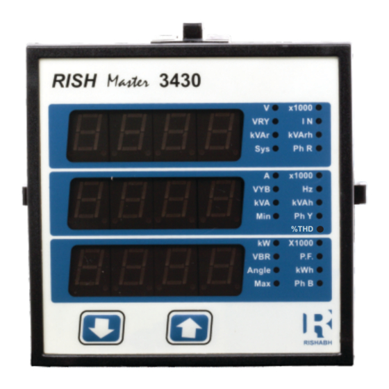
1. Introduction The 3430 is a panel mounted 96 x 96mm DIN Quadratic Digital metering system for the measurement important electrical parameters like AC voltage, AC Current, Frequency, Power, Energy(Active / Reactive / Apparent) . The instrument integrates accurate measurement technology (All Voltages & Current measurements are True RMS upto 15th Harmonic) with 3 line 4 digits Ultra high brightness LED display. - Page 5 TABLE 1: Units of Measured Parameters Measurement Volts System Voltage Amps System Current Volts Voltage VL1-N(4wire only) Volts Voltage VL2-N(4wire only) Volts Voltage VL3-N(4wire only) ( for 3 / 4 wire) Volts Voltage VL1-L2 ( for 3 / 4 wire) Volts Voltage VL2-L3 ( for 3 / 4 wire)
- Page 6 Units of Measured Parameters Measurement ( for 3 / 4 wire) V1 THD* ( for 3 / 4 wire) V2 THD* ( for 3 / 4 wire) V3 THD* ( for 3 / 4 wire) I1 THD ( for 3 / 4 wire) I2 THD ( for 3 / 4 wire) I3 THD...
-
Page 7: Measurement Reading Screens
Measurement Reading Screens In normal operation the user is presented with one of the measurement reading screens out of several screens. These screens may be scrolled through one at a time in incremental order by pressing the “ Up key” and in decremental order by pressing “... - Page 8 Parameter Screens 3 Phase Phase Power Factor R* System Voltage Reactive Phase Power Factor Y* System Current Energy Phase Power Factor B* System Active Power Export R Phase V L-N* Apparent Voltage % Y Phase V L-N* Energy B Phase V L-N* VRY V L-L Min.
- Page 9 *Note :Sys type selection screen is not available in 1 phase.
-
Page 10: Programming
3. Programming The following sections comprise step by step procedures for configuring the 3430 for individual user requirements. To access the set-up screens press and hold the “ Down” and “ Up” Key simultaneously for 5 seconds. This will take the User into the Password Protection Entry Stage (Section 3.1). - Page 11 x1000 KVAr KVArh Ph R x1000 KVAh Ph Y %THD x1000 P.F. Angle Ph B Enter Password, second digit entered, prompt for third x1000 digit. KVAr KVArh (* Denotes that decimal point will be flashing). Ph R x1000 Use the “ Down”...
- Page 12 Enter Password, fourth digit entered, awaiting x1000 verification of the password. KVAr KVArh Ph R x1000 KVAh Ph Y %THD x1000 P.F. Angle Ph B x1000 KVAr KVArh Ph R x1000 Password confirmed. KVAh Ph Y %THD x1000 Pressing “ Down”...
- Page 13 New / Change Password (*Decimal point indicates that this will be flashing). x1000 KVAr KVArh Ph R Pressing the “ Down” key will scroll the value of the first digit from 0 through to 9, the value will wrap from 9 x1000 KVAh round to 0.
-
Page 14: Set Up Screens
New / Change Password, third digit entered, prompting x1000 for fourth digit. (* denotes that decimal point will be KVAr KVArh flashing). Ph R Pressing the “ Down” key will scroll the value of the x1000 KVAh fourth digit from 0 through to 9, the value will wrap from Ph Y %THD 9 round to 0. -
Page 15: Potential Transformer Primary Value
System Type Confirmation This screen will only appear following the edit of system type. If system type is to be Downed again, x1000 KVArh KVAr Ph R Pressing the “ Up” key sets the displayed value and x1000 x1000 will advance to “Potential Transformer Primary Value KVAh KVAh Ph Y... - Page 16 Potential Transformer primary Digit Edit x1000 Pressing the “ Down” key will scroll the value of KVArh KVAr Ph R the most significant digit from 0 through to 9 unless x1000 x1000 the presently displayed Potential Transformer Primary KVAh KVAh Ph Y Ph Y Value together with the Current Transformer Primary...
-
Page 17: Current Transformer Primary Value
Potential Transformer Primary Value Confirmation x1000 This screen will only appear following an edit of the KVArh KVAr Potential Transformer Primary Value. Ph R x1000 x1000 If the scaling is not correct, pressing the “ Down” KVAh KVAh Ph Y Ph Y key will return to the “Potential Transformer Primary %THD... -
Page 18: Current Transformer Secondary Value
Note : the flashing decimal point indicates the cursor position, a steady decimal point will be present to identify the scaling of the number until the cursor position coincides with the steady decimal point position. At this stage the decimal point will flash. When the least significant digit has been set pressing the “... - Page 19 Primary Value results in a maximum power of greater than 666.6 MVA in which case the digit x1000 range will be restricted, the value will wrap. KVArh KVAr Ph R Example: If primary value of PT is set as x1000 x1000 692.8kV L-L (max value) then primary value KVAh...
-
Page 20: Reset
3.2.5 Current Transformer Secondary Value This screen is used to set the secondary value for Current Transformer. Secondary value “5” for 5A or x1000 “1” for 1A can be selected. Pressing “ Up” key KVArh KVAr Ph R accepts the present value and advances to the x1000 x1000 Reset parameter screen (See Section 3.2.6) - Page 21 3.2.6 Reset Parameter : The following screens allow the users to reset the All parameters,Energy , Lo(Min), hi(Max). Pressing “ Up” key advances to Auto scroll selection screen x1000 KVArh KVAr Ph R Pressing the “ Down” key will enter the “Reset x1000 x1000 option”...
- Page 22 Reset ALL Confirmation. x1000 Pressing the “ Down” key will re-enter the KVArh KVAr Ph R “Reset option Select mode. x1000 x1000 KVAh KVAh Pressing “ Up” key resets ALL the readings Ph Y Ph Y %THD %THD and advances to the Auto scroll. x1000 P.F.
-
Page 23: Auto Scrolling
3.2.7 Auto Scrolling : This screen allows user to enable screen scrolling. x1000 KVAr KVArh Auto scrolling Edit. Ph R x1000 Pressing “ Up” key accepts the present status and KVAh Ph Y %THD advance to the Low Current noise cutoff x1000 P.F. - Page 24 Low current noise cutoff Confirmation. x1000 KVAr KVArh pressing the “ Down” key will re-enter the “Low Ph R current Noise cutoff Edit” mode. x1000 KVAh Ph Y Pressing “ Up” key set displayed value and %THD x1000 Advance to the Rs485 address selection. P.F.
- Page 25 Enter Address, first digit entered, prompt for second x1000 digit (* Denotes that decimal point will be flashing). KVAr KVArh Ph R x1000 Use the “ Down” key to scroll the value of the KVAh second digit Ph Y %THD x1000 P.F.
-
Page 26: Rs 485 Baud Rate
3.2.10 RS 485 Baud Rate : This screen allows the user to set Baud Rate of RS 485 port. The values displayed on screen are in kbaud . x1000 Pressing “ Up” key accepts the present value and KVArh KVAr Ph R advance to the Parity Selection (see section 3.2.11). -
Page 27: Rs 485 Parity Selection
3.2.11 RS 485 Parity Selection : This screen allows the user to set Parity & number of stop bits of RS 485 port. Pressing “ Up” key accepts the present value and x1000 advance to the Pulse output 1 selection KVArh KVAr (see section 3.2.12). - Page 28 3.2.12. Assignment of Energy to pulse output 1 : This screen allows the user to assign pulse output1 to energy Pressing “ Up” key accepts the present setting x1000 and advance to “Assignment of Energy to Pulse KVArh KVAr Output 2”(see section 3.2.13). Ph R x1000 x1000...
- Page 29 3.2.13. Assignment of Energy to pulse output 2 : This screen allows the user to assign pulse output 2 to energy Pressing “ Up” key accepts the present setting and advance to “Pulse Duration”(see section x1000 3.2.14). KVArh KVAr Ph R Pressing the “...
- Page 30 3.2.14 Pulse Duration : This screen applies to the Relay Pulsed output only. This screen allows the user to set Relay energise time in milliseconds. Pulse Duration Edit. x1000 Pressing “ Up” key accepts the present value and KVArh KVAr Ph R advance to the Pulse rate (see section 3.2.15).
- Page 31 3.2.15. Pulse Rate This screen applies to the Relay Output option only. The screen allows user to set the energy pulse rate divisor. Divisor values can be selected through 1,10,100,1000 in Wh . Pressing “ Up” key accepts the presents value x1000 and advances to the “Analog output 1”...
- Page 32 3.2.16 Analog Output 1 Selection : ( Optional ) This screen is for analog output 1 only . It allows the user to set analog output 1 to corresponding measured parameter . Refer table “ Parameter for Analog output “. Pressing “...
- Page 33 3.2.17 Analog Output 2 Selection : ( Optional ) This screen is for analog output 2 only . It allows the user to set analog output 2 to corresponding measured parameter . Refer table “ Parameter for Analog output “. Pressing “...
- Page 34 3.2.18 Energy Update Rate : This screen is for energy update rate. it allows user to set energy update rate in minutes. It is settable from x1000 x1000 1 to 60 min. KVArh KVArh KVAr KVAr Ph R Ph R x1000 x1000 Pressing the “...
- Page 35 Ex. If energy display on modbus is set Wh & It will set Energy digit count to 10 then energy will reset after “9,999,999,999” & then will Rollback to zero. Pressing “ Up key “ will advance to Energy digit reset count confirmation screen. Pressing the “...
- Page 36 Pressing the “ Up” key advances to the returns to Measurement screen. Energy Display On Modbus Confirmation. x1000 KVArh KVAr This screen will only appear following an edit of the Ph R Energy Display On Modbus. x1000 x1000 KVAh KVAh Pressing the “...
- Page 37 4. Analog Output ( optional ) : This module provides two d.c. isolated outputs .There are two output options 1) Two 0 - 1mA outputs , internally powered . 2) Two 4 - 20mA outputs , internally powered . The 0 -1mA output module has an 0V return on each end of the 4 way connector ( Please refer section 15 for connection details ) On both modules the output signals are present on pins A1(Analog Output 1) &...
- Page 38 Diagram 1 : ( 4 -20 mA ) 0 (12 mA) 270 (8 mA) 90 (16 mA) 181 (4 mA) 180 (20 mA) Diagram 2 : ( 0 - 1 mA ) 0 (0.5 mA) 270 (0.25 mA) 90 (0.75 mA) 181 (0 mA) 180 (1 mA)
- Page 39 TABLE 2 : Parameter for Analog Output Range Parameter 3P 4W 3P 3W 1P 2W Analog Output None – INPUT VOLTAGE L1 0 - 100 % 2 INPUT VOLTAGE L2 0 - 100 % ...
- Page 40 Range Parameter 1P 2W 3P 3W 3P 4W Analog Output 0 - 120 % 27 ACTIVE POWER SUM 29 APPARENT POWER SUM 0 - 120 % 31 REACTIVE POWER SUM 0 - 120 % ...
- Page 41 5. Relay output (Optional) : This instrument is provided with either 1 or 2 relay for pulse output . Pulse Output : Pulse output is the potential free, very fast acting relay contact which can be used to drive an external mechanical counter for energy measurement. This instrument’s pulse output can be congured to any of the following parameter...
- Page 42 6. RS 485 ( ModBus ) Output : This instrument supports MODBUS (RS485) RTU protocol( 2-wire ) . Connection should be made using twisted pair shielded cable. All "A" and "B" connections are daisy chained together. The screens should also be connected to the “Gnd” terminal. To avoid the possibility of loop currents, an Earth connection should be made at one point on the network.Loop (ring) topology does not require any termination load.
- Page 43 The each byte in RTU mode has following format: 8-bit binary, hexadecimal 0-9, A-F 2 hexadecimal characters contained in each 8-bit eld of the message 4 bytes (32 bits) per parameter. Format of Data Bytes Floating point format ( to IEEE 754) Most signicant byte rst (Alternative least signicant byte rst) 2 byte Cyclical Redundancy Check (CRC) Error Checking Bytes...
- Page 44 This function code is not supported by the instrument. Illegal function Attempt to access an invalid address or an attempt to read Illegal Data or write part of a oating point value Address Attempt to set a oating point variable to an invalid value Illegal Data Value Accessing 3 X register for reading measured values:...
- Page 45 Number of register Hi : Most signicant 8 bits of Number of registers requested. Number of register Lo : Least signicant 8 bits of Number of registers requested. (Note : Two consecutive 16 bit register represent one parameter.) Response: Volt3 (219.25V) 43 (Hex) 5B (Hex) 01 (Hex) 04 (Hex) 04 (Hex)
- Page 46 Address Parameter Modbus Start Address Hex 1P 2W 3P 4W 3P 3W High Byte (Register) Low Byte 30015 30017 30019 30021 30023 30025 VAR1 ...
- Page 47 Address Parameter Modbus Start Address Hex 1P 2W 3P 4W 3P 3W High Byte (Register) Low Byte 30067 Phase Angle Ave 30069 Phase Angle Sum 30071 Freq 30073 Wh Import ...
- Page 48 Address Parameter Modbus Start Address Hex 3P 4W 3P 3W 1P 2W High Byte (Register) Low Byte Varh Export 30151 (On Update Rate) 30153 (On Update Rate) Model Number 30197 Version Number ...
- Page 49 Accessing 4 X register for Reading & Writing : Each setting is held in the 4X registers .ModBus code 03 is used to read the current setting and code 16 is used to write/change the setting. Refer Table 5 for 4 X Register addresses. Example : Reading System type System type : Start address = 0A (Hex)
- Page 50 Response: System Type ( 3phase 4 wire = 3 ) 01 (Hex) Device Address 03 (Hex) Function Code Byte Count 04 (Hex) Data Register1 High Byte 40 (Hex) Data Register1Low Byte 40 (Hex) Data Register2 High Byte 00 (Hex) Data Register2 Low Byte 00(Hex) EE (Hex) CRC Low...
- Page 51 Byte Count 04 (Hex) Data Register-1High Byte 40 (Hex) Data Register-1 Low Byte 00(Hex) Data Register-2 High Byte 00(Hex) Data Register-2 Low Byte 00(Hex) 66 (Hex) CRC Low CRC High 10 (Hex) Byte Count : Total number of data bytes received. Data register 1 High Byte : Most signicant 8 bits of Data register 1 of the parameter requested.
- Page 52 Start Address High : Most signicant 8 bits of starting address of the parameter requested. Start Address low :Least signicant 8 bits of starting address of the parameter requested. Number of register Hi : Most signicant 8 bits of Number of registers requested. Number of register Lo : Least signicant 8 bits of Number of registers requested.
- Page 53 Address Parameter Modbus Start Address Hex Parameter Read / Write (Register) Low Byte High Byte 40037 System Power R/Wp 40039 Energy digit reset count 40041 Register Order/Word Order R/Wp CT Secondary 40043 R/Wp 40045 R/Wp PT Secondary R/Wp 40049 Pulse1 Parameter select 40061 R/Wp Pulse2 Parameter select...
- Page 54 Explanation for 4 X register : Address Parameter Description This address is used to set energy display on MODBUS in Wh, 40005 Energy display K Wh & M w h. Write one of the following value to this address. on Modbus 1 = Energy in Wh.
- Page 55 Address Parameter Description 40019 Rs485 Set-up This address is used to set the baud rate, Parity, Number of Code stop bits. Refer to Table 6 for details. 40021 Node This register address is used to set Device address Address between 1 to 247 . This address is used to set pulse divisor of the Pulse output.
- Page 56 Address Parameter Description PT Primary This address allows the user to set PT Primary value. 40033 The maximum settable value is 692.8kV L-L depends on the per phase 666.6MVA Restriction of power combined with CT primary 40035 CT Pimary This address allows the user to set CT Primary value. The maximum settable value is 9999 &...
- Page 57 Address Parameter Description This address is used to read and write the CT secondary value CT secondary 40043 write one of the following values to this address. 1=1A CT secondary 5=5A CT secondary writing any other value will return an error. 40045 PT secondary This address is used to read and write the PT secondary value.
- Page 58 Address Parameter Description 40077 This address is used to activate or de-activate the Auto scroll Auto setting. Scroll 0-Deactivate 1 (Decimal)-Activate Writing any other value will return an error. This address is used to activate or de-activate the 30 mA noise 30mA Noise 40079 current elimination write...
- Page 59 Address Parameter Description The user can set respective Energy Overow starting count 40119 Energy in these registers. Valid range is 0-999999. Overow 40129 Start Count Table 6 : RS 485 Set-up Code Decimal value Parity Baud Rate Stop Bit 19200 NONE 19200 NONE...
- Page 60 Table 7 : Pulse1 & Pulse2 Conguration Conguration Code Import Active Energy Export Active Energy Import Reactive Energy Export Reactive Energy Apparent Energy 6.1 User Assignable Modbus Registers: This instrument contains the 20 user assignable registers in the address range of 0x200 (30513) to 0x226 (30551) (see Table 8).
- Page 61 Address Parameter Modbus Start Address (Hex) Assignable Register High Byte Low Byte (Register) Number. Assignable Reg 7 30525 Assignable Reg 8 30527 30529 Assignable Reg 9 30531 Assignable Reg 10 30533 Assignable Reg 11 30535 Assignable Reg 12 Assignable Reg 13 30537 Assignable Reg 14 30539...
- Page 62 Address Parameter Modbus Start Address (Hex) Mapping Register High Byte Low Byte (Register) Number. 40521 Mapped Add for register #0x0210 40522 Mapped Add for register #0x0212 40523 Mapped Add for register #0x0214 40524 Mapped Add for register #0x0216 40525 Mapped Add for register #0x0218 40526 Mapped Add for register #0x021A Mapped Add for register #0x021C...
- Page 63 Byte Count 04 (Hex) Voltage 2 * Data Register-1High Byte 00 (Hex) (3X Address 0x0002) Data Register-1 Low Byte 02 (Hex) Power Factor 1 * Data Register-2 High Byte 00 (Hex) (3X Address 0x001E) Data Register-2 Low Byte 1E (Hex) CB (Hex) CRC lOW CRC High...
- Page 64 Query: 01 (Hex) Device Address 04 (Hex) Function Code Start Address High 02 (Hex) 00 (Hex) Start Address Low Number of Registers Hi 00 (Hex) Number of Registers Lo 04 (Hex) ** F0 (Hex) CRC Low CRC High 71 (Hex) Start Address High : Most signicant 8 bits of starting address of User assignable register.
- Page 65 Data Register-3 High Byte 3F (Hex) Data Register-3 Low Byte 80 (Hex) Power Factor 1Data Data Register-4 High Byte 00 (Hex) Data Register-4 Low Byte 00 (Hex) 79 (Hex) CRC Low CRC High 3F (Hex) User Assignable mapping Registers User Assignable Data Registers (Starting (Starting ( 4X Registers Table10 )
- Page 66 To get the data through User assignable Register use following steps: 1) Assign starting addresses(Table3) of parameters of interest to a “User assignable mapping registers” in a sequence in which they are to be accessed (see section “Assigning parameter to user assignable registers”) 2) Once the parameters are mapped data can be acquired by using “User assignable data register “...
- Page 67 Sign of Sign of Sign of Inductive / Connections Quadrant Active Reactive Power Capacitive Power ( P ) Power ( Q ) Factor ( PF ) Import Import Export Export Inductive means Current lags Voltage Capacitive means Current leads Voltage When the instrument displays Active power ( P )with “...
- Page 68 As the front of the enclosure conforms to IP54 it is protected from water spray from all directions, additional protection to the panel may be obtained by the use of an optional panel gasket. The terminals at the rear of the product should be protected from liquids. The instrument should be mounted in a reasonably stable ambient temperature and where the operating temperature is within the range -10 to 55 C .
- Page 69 3. To protect the product against permanent damage, surge transients must be limited to 2kV pk. It is good EMC practice to suppress differential surges to 2kV at the source. The unit has been designed to automatically recover in the event of a high level of transients.
-
Page 70: Connection Diagrams
8.4 Auxiliary Supply instrument should ideally be powered from a dedicated supply, however it may be powered from the signal source, provided the source remains within the limits of the chosen auxiliary voltage. 8.5 Fusing It is recommended that all voltage lines are tted with 1 amp HRC fuses. 8.6 Earth/Ground Connections For safety reasons, CT secondary connections should be grounded in accordance with local regulations. - Page 71 3-PHASE 4-WIRE UNBALANCED LOAD DIGITAL METERING SYSTEM 2 5 8 11 1 3 4 6 7 9 13 14 SUPPLY P1 S1 P1 S1 SINGLE PHASE DIGITAL METERING SYSTEM SUPPLY P1 S1...
- Page 72 10. Specication : System 3 Phase 3 Wire / 3 phase 4 Wire programmable at site 1 Phase 2 Wire as per order Inputs Nominal input voltage (AC RMS) Phase-Neutral 57.7 - 346 V Line-Line 100 - 600 V Max continuous input voltage 120% of Rated Value Max short duration input voltage 2 x Rated Value...
- Page 73 Operating Measuring Ranges Voltage 10 .. 120 % of Rated Value Current 5 .. 120 % of Rated Value Frequency 40 .. 70 Hz 0.5 Lag ... 1 ... 0.8 Lead Power Factor Accuracy Accuracy 1: Voltage 0.5 % of range ...
- Page 74 0.5 % of range Re - Active Energy 0.5 % of range Apparent Energy 1 % of Unity Power Factor 1 % of range Angle 1 % of Output end value Analog Output 1 % Total Harmonic Distortion Neutral Current ...
- Page 75 Current Range 10... 100% of Nominal Value. 20... 100% of Nominal Value for THD. cosØ / sinØ = 1 Power For Active / Reactive Power & Energy 10... 100% of Nominal Current & 50... 100% of Nominal Voltage. Power Factor / Phase Angle 40...
- Page 76 Standards EMC Immunity IEC 61326 10V/m min-Level 3 industrial low level electromagnetic radiation environment IEC 61000-4-3. IEC 61010-1 , Year 2001 Safety IP for water & dust IEC 60529 Isolation Dielectric voltage withstand 2.2 kV RMS 50 Hz for 1 minute test between circuits and between all electrical circuits accessible surfaces...
-
Page 77: Analog Output Option
Pulse output Option ( 1 or 2 Relay ) : Relay 1NO + 1NC Switching Voltage & Current Switching Voltage & Current 240VDC , 5Amp. Default Pulse rate Divisor 1 per Wh (up to 3600W), 1 per kWh (up to 3600kW), 1 per MWh (above 3600 kW) Programmable on site Pulse rate Divisors... - Page 78 11. Connection for Optional Pulse Output / RS 485 / Analog Output ( rear view of the instrument ) : 1. RS 485 Output + One Pulse + Two Analog Output N/O N/C COM A2 Gnd RS 485 Relay 2 0 - 1mA 2.
- Page 79 The Information contained in these installation instructions is for use only by installers trained to make electrical power installations and is intended to describe the correct method of installation for this product. It is the user's responsibility to determine the suitability of the installation method in the user’s eld conditions.
Need help?
Do you have a question about the Master 3430 and is the answer not in the manual?
Questions and answers