Table of Contents
Advertisement
Advertisement
Table of Contents

Related Manuals for Rish OPTIMA VAF


Summary of Contents for Rish OPTIMA VAF
- Page 1 Operating Manual RISH OPTIMA VAF 2-60-006-00-00511_Rev. B - 9/2023...
-
Page 2: Table Of Contents
DIGITAL MULTIFUNCTION INSTRUMENT Programmable Multi-function Digital Panel Meter Installation & Operating Instructions Section Contents Introduction Measurement Reading Screens Programming 3.1 Password Protection 3.2 Set Up Screens 3.2.1 System Type 3.2.2 Potential Transformer Primary value 3.2.3 Current Transformer Primary value 3.2.4 Potential Transformer Secondary value 3.2.5 Current Transformer Secondary value 3.2.6 Reset 3.2.7 Auto Scrolling... - Page 3 Installation 4.1 EMC Installation Requirements 4.2 Case Dimensions and Panel Cut-out 4.3 Wiring Auxiliary Supply Fusing Earth / Ground Connections Connection Diagrams Optional Pluggable Module Specification...
-
Page 4: Introduction
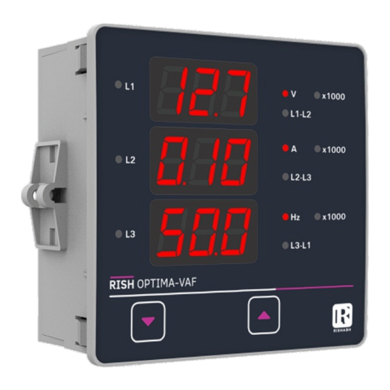
1. INTRODUCTION The VAF is a panel mounted 96 x 96mm DIN Quadratic Digital Panel Meter for the measurement of important electrical parameters like AC Voltage, AC Current, RPM, Frequency. The instrument integrates accurate measurement technology (All Voltages & current measurements are True RMS upto 15th Harmonic) with 3 line 3 digits Ultra high bright LED display. -
Page 5: Programming
3. Programming The following sections comprise step by step procedures for conguring the VAF for individual user requirements. To access the set-up screens press and hold the “DOWN” and “UP” keys Simultaneously. This will take the User into the Password Entry screen (Section 3.1). In Setup mode, if none of the key pressed within 1 min, it will returns operation to the measurement mode. - Page 6 Enter Password, rst digit entered, prompt for second digit.(* Denotes Volt x1000 that decimal point will be ashing). L1-L2 x1000 Press the “DOWN” key to scroll the value of the second digit from 0 L2-L3 through to 9, the value will wrap from 9 round to 0. x1000 L3-L1 Press the “UP”...
- Page 7 Password Incorrect. The unit has not accepted the Password entered. x1000 Volt L1-L2 x1000 Pressing the “DOWN” key will return to the Enter Password stage. L2-L3 x1000 Pressing the “UP”key exits the Password menu and returns operation to L3-L1 the measurement reading mode. New / Change Password (*Decimal point indicates that this will be ashing).
-
Page 8: Set Up Screens
New / Change Password, second digit entered, prompting for third digit. Volt x1000 (*decimal point indicates that this will be ashing). L1-L2 x1000 Pressing the “DOWN” key will scroll the value of the third from 0 through L2-L3 to 9, the value will wrap from 9 round to 0. x1000 L3-L1 Pressing the “UP”... -
Page 9: Potential Transformer Primary Value
System Type Edit Volt x1000 L1-L2 This screen appears only if “DOWN” key is pressed in previous Menu. x1000 L2-L3 Pressing “DOWN” scrolls through the values available. x1000 L3-L1 Pressing “UP” Key advances to the system type Conrmation menu. System Type Conrmation x1000 Volt L1-L2... - Page 10 Initially the PT value must be selected pressing the “DOWN” key will move the decimal point position to the right side until it reaches # # #. after which it will return to #. # # with x1000 annunciation. Pressing the “UP” key accepts the present multiplier (Decimal Point position with x1000 annunciation and advances to the “Potential Transformer Primary Digit Edit”...
-
Page 11: Current Transformer Primary Value
Screen showing display of 11.0 k VL-L i.e. 11000 Volts Line to Line indicating steady decimal point and cursor ashing at the “hundreds of volts” position as shown below. Potential Transformer Primary Value Conrmation Volt x1000 L1-L2 This screen will only appear following an edit of the x1000 Potential Transformer Primary Value. -
Page 12: Potential Transformer Secondary Value
3.2.4. Potential Transformer Secondary Value This screen is used to set the secondary value for Potential Transformer Volt x1000 Secondary value from 100V to 500VL-L. L1-L2 x1000 Pressing “UP” key accepts the present value and then advances to L2-L3 Current Transformer Secondary value edit mode. x1000 L3-L1 Pressing the “DOWN”... -
Page 13: Current Transformer Secondary Value
3.2.5. Current Transformer Secondary Value This screen is used to set the secondary value for Current Transformer Volt x1000 Secondary value from 1 and 5 Amperes. L1-L2 x1000 Pressing “UP” key accepts the present value and then advances to L2-L3 RESET menu.. -
Page 14: Reset
3.2.6. Reset The following screens allow the users to reset the run hour, ON Hour, No. Volt x1000 Of Interruptions, Min and Max. Values of Voltage and Current. L1-L2 x1000 Pressing the “DOWN” key will enter the “Reset edit” menu. L2-L3 x1000 L3-L1... - Page 15 3.2.7 Screen Auto scrolling / Fixed Screen selection This menu allow to select scrolling or xed screen. Volt x1000 L1-L2 Pressing “UP” key enters conrmation of Fixed Screen. x1000 L2-L3 Pressing of “DOWN” key enters to Edit menu. x1000 L3-L1 Fixed Screen / Auto Scrolling Edit.
- Page 16 3.2.8 No. of Poles Selection : This screen enables to set No. of poles on a Generator of which RPM is to be measured and to which the instrument is connected to measure its Volt x1000 L1-L2 output parameters. x1000 L2-L3 Pressing “DOWN”...
-
Page 17: Relay Limit Parameter (Optional)
3.2.9 Relay Limit Parameter selection (Optional) This screen enables user to select Parameter for limit monitoring via a Volt x1000 Relay. L1-L2 x1000 Pressing “UP” key selects the displayed parameter for monitoring and L2-L3 enters trip point selection screen. x1000 L3-L1 Pressing “DOWN”... - Page 18 Trip point selection This screen will not appear if parameter None (00) is Selected in previous Volt x1000 menu. The trip point can be set as % of the Nominal value of L1-L2 selected parameter (Refer Table 2). x1000 L2-L3 Pressing “DOWN”...
-
Page 19: Installation
4. Installation Mounting of VAF is featured with easy “Clip- in” Panel mounting. Push the meter in panel slot (size 92 x92 mm), it will click t into panel with the four integral retention clips on two sides of meter. Swivel screw If required Additional support is provided with swivel Retention clip for... -
Page 20: Emc Installation Requirements
4.1 EMC Installation Requirements This product has been designed to meet the certication of the EU directives when installed to a good code of practice for EMC in industrial environments. e.g. screened output and low signal input leads or have provision for tting RF suppression components, such as ferrite absorbers, line lters etc., in the event that RF elds cause problems. -
Page 21: Case Dimensions And Panel Cut-Out
4.2 Case Dimension and Panel Cut Out 55 mm 96 mm 92mm+0.8 62 mm Display Area 4 mm With optional Panel Cutout 42 mm Limit switch. 4.3 Wiring Input connections are made directly to screw-type terminals with indirect wire pressure. Numbering is clearly marked on the connector. -
Page 22: Fusing
MODEL : OPTIMA VAF INPUT :500VL-L, 5A/1A, 45-65Hz P1 S1 AUX SUPPLY :40V-300V AC-DC , 3VA SR NO : 14/02/3232 ORDER CODE : RISH OPTIMA VAF - 3L- EA - L 3-PHASE 3-WIRE UNBALANCED LOAD AUX. LIMIT SW. 13 14... -
Page 23: Optional Pluggable Module
6. Optional Pluggable Module Max continuous input 120% of Rated value voltage Max short duration 2 x Rated value (1s Insert the Addon Assembly here and input voltage application repeated t the assembly with the screws 10 times at 10s intervals) Nominal input voltage <... - Page 24 Auxiliary Relay External Auxiliary 40V to 300V AC/DC Settable parameters as per table 2 Supply (+/- 5%) Trip Point setting 10%...120% of set range of parameter 20V to 40V AC / (except frequency 20V to 60V DC which is 10%...100%) Frequency Range 45 to 65 Hz Hysteresis...
- Page 25 Applicable Standards: Environmental IEC 61326 Operating temperature -10 to +55°C Immunity IEC 61000-4-3. Storage temperature -20 to +65°C 10V/m min – Level 3 Relative humidity 0... 90% non industrial Low level condensing Safety IEC 61010-1-2010 , Warm up time Minimum 3 minute Permanently Shock 15g in 3 planes...
- Page 26 WARRANTY Dear Customer, You are now the privileged owner of MFM, a product that ranks the rst of its kind in the world. Company provides 12 months warranty from the original date of Purchase against defective material and workmanship. In the unlikely event of failure of the instrument / accessories within the warranty period. Company will repair meter / accessories free of charge.
Need help?
Do you have a question about the OPTIMA VAF and is the answer not in the manual?
Questions and answers