Table of Contents
Advertisement
Quick Links
Advertisement
Table of Contents

Related Manuals for Rish ED 4311 Mod


Summary of Contents for Rish ED 4311 Mod
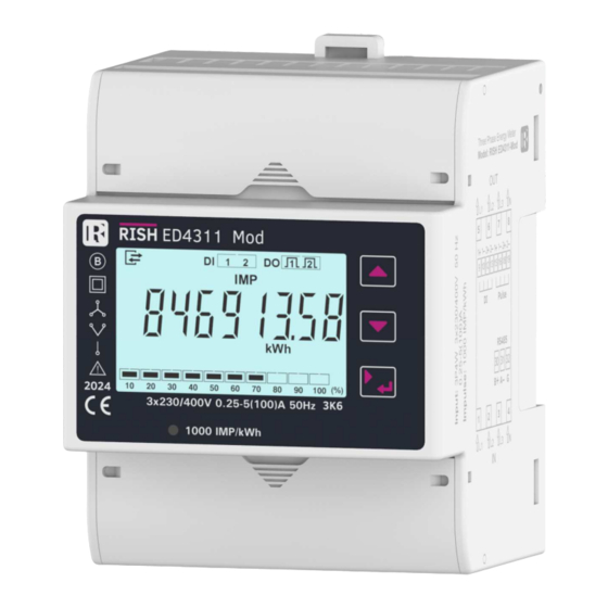
- Page 1 Operating Manual RISH ED 4311 Mod / 4301 4TS...
-
Page 3: Table Of Contents
DIRECT CONNECTED ENERGY METER Installation & Operating Instructions Section Contents Introduction LCD Display 2.1 Introduction LCD Display Symbols and Indications 2.2.1 Digital Input Indication 2.2.2 SO/DI Output Indication 2.2.3 Communication Indication 2.2.4 Tariff Energy Indication 2.2.5 Load Graph Indication 2.3 Measurement Screens Navigation Map 2.4 Setup Screens Navigation Map Programming 3.1 Password Protection... - Page 4 3.2.3.1.1.3 Parameter Selection 3.2.3.1.1.4 Pulse Duration 3.2.3.1.1.5 Pulse Rate 3.2.3.1.1.6 Quit SO Output Selection 3.2.3.2 SO 2 Selection 3.2.3.3 Quit Output Parameters 3.2.4 Display Parameters 3.2.4.1 Backlit 3.2.4.2 Display Test Screen 3.2.4.3 Quit Display Parameters 3.2.5 Reset Parameters 3.2.5.1 Partial Energy Reset 3.2.5.2 Max Demand Reset 3.2.5.3 Setup Parameter Reset 3.2.5.4 Code Reset...
-
Page 5: Introduction
1. INTRODUCTION The Direct Connected Energy Meter is a DIN Rail mounted Digital Meter, primarily for bidirectional Active, Reactive and Apparent Energy measurement intended for use in industrial, commercial and residential electrical energy metering. It also accurately measures important electrical parameters like Voltage, Current, Frequency, Active, Reactive and Apparent Power, and Power Factor in Three Phase and Single Phase Networks. -
Page 6: Lcd Display Symbols And Indications
2. LCD Display 2.1. Introduction The meter displays more than 100 measurement parameters including Total Energies, Tariff, Partial and Per Phase Energies and also other important electrical parameters like Max Demand, Voltage, Current, Frequency, Active Power, Reactive Power, Apparent Power and Power Factor on individual screens. The screens are mapped in such an intuitive way that the user can easily navigate through all parameters using front three keys. -
Page 7: So/Di Output Indication
2.2.2. SO Output Indication The meter has two opto-isolated pulse outputs that can be configured for any one of the Active (Total /Import /Export) or Reactive (Total/Import/Export) Energy parameter. The status of digital output is indicated on LCD as shown below: Pulse output at SO1. - Page 8 TABLE 1 : Measurement Parameters: Parameter On Modbus On Display Parameters 3P 4W 3P 3W 1P 2W 3P 4W 3P 3W 1P 2W Import Active Energy Export Active Energy ...
- Page 9 TABLE 1 : Measurement Parameters (contd.): Parameter On Modbus On Display Parameters 3P 4W 3P 3W 1P 2W 3P 4W 3P 3W 1P 2W T1 Partial Export Reactive Energy T2 Import Active Energy ...
- Page 10 TABLE 1 : Measurement Parameters (contd.): Parameter On Modbus On Display Parameters 3P 4W 3P 3W 1P 2W 3P 4W 3P 3W 1P 2W T4 Partial Export Active Energy T4 Partial Import Reactive Energy ...
- Page 11 TABLE 1 : Measurement Parameters (contd.): Parameter On Modbus On Display Parameters 3P 4W 3P 3W 1P 2W 3P 4W 3P 3W 1P 2W System Phase Angle L1, L2, L3 Phase Angle ...
- Page 12 2.3. Measurement Parameters Screen Navigation Map : UP KEY : DOWN KEY : RIGHT KEY T1 Total Active Energy L1 Total Active Energy Total Active Energy L2 Total Active Energy T2 Total Active Energy L3 Total Active Energy T3 Total Active Energy L1 Import Active Energy T4 Total Active Energy L2 Import Active Energy...
- Page 13 Measurement Parameters Screens Navigation Map cont... T1 Total Apparent Energy L1 Total Apparent Energy Total Apparent Energy L2 Total Apparent Energy T2 Total Apparent Energy L3 Total Apparent Energy T3 Total Apparent Energy T4 Total Apparent Energy Partial Import Active Energy Partial Total Active Energy T1 Partial Import Active Energy T2 Partial Import Active Energy...
- Page 14 Measurement Parameters Screens Navigation Map cont... Partial Import Reactive Energy Partial Total Reactive Energy T1 Partial Import Reactive Energy T2 Partial Import Reactive Energy T3 Partial Import Reactive Energy T4 Partial Import Reactive Energy Partial Export Reactive Energy T1 Partial Export Reactive Energy T2 Partial Export Reactive Energy T3 Partial Export Reactive Energy T4 Partial Export Reactive Energy...
- Page 15 Measurement Parameters Screens Navigation Map cont... System Apparent Power Max Demand Current Max Demand L1 System Current Max Demand Current Max Demand L2 Current Max Demand L3 Voltage L1 System Voltage Voltage L2 Voltage L3 Voltage L12 Voltage L23 Voltage L31 Current L1 System Current Current L2...
- Page 16 Measurement Parameters Screens Navigation Map cont... Power Factor L1 System Power Factor Power Factor L2 Power Factor L3 Phase Angle L1 System Phase Angle Phase Angle L2 Phase Angle L3 Voltage THD L1 System Voltage THD Voltage THD L2 Voltage THD L3 Current THD L1 System Current THD Current THD L2...
- Page 17 Meter Info Screens: This screen helps the user to know some basic parameters without being able to edit them. The Parameters are : Address, Baud Rate, Parity/Stop Bit, Software Version, Serial Number, Input-Output Options and Power Fail counts. This screens will show the This screens will show the This screens will show the parity and stop bit.
-
Page 18: Setup Screens Navigation Map
2.4. Setup Parameters Screens Navigation Map CodE (PassWord ) SEL (Select) SYS. PArA. Ser. PArA. Out. PArA. diSP. PArA. (System Parameter) (Serial Comm.Parameter) (Output Parameter) (Display Parameter) (Sec 3.2.2) (Sec 3.2.1) (Sec 3.2.3) (Sec 3.2.4) Addr. tYP. SEL. S0.1 (Modbus Address) (System Type / Network) bACLit. -
Page 19: Programming
3. PROGRAMMING The following sections comprise step by step procedures for configuring the Energy Meter according to individual user requirements. To access the set-up screens press and hold “Enter” key for 5 seconds. This will take the user into the Password Protection Entry Stage (Section 3.1). 3.1. - Page 20 Enter Password, second digit entered, prompt for third digit. Press the “ ” key to scroll the value of first digit from 0 through to 9, the value rolls back from 9 round to 0 and “ ” key to scroll the value of first digit from 9 through to 0, the value rolls back from 0 round to 9.
- Page 21 Password Incorrect. The unit has not accepted the Password entered The unit automatically returns to the Enter Password stage. New / Change Password Prompting for first digit. Press the “ ” and “ ” keys to scroll the value of first digit from 0 through to 9 and from 9 through to 0,respectively with digit roll around feature.
-
Page 22: Menu Selection
New/ Change Password, third digit entered, prompting for fourth digit. . Press the “ ” and “ ” keys to scroll the value of second digit from 0 through to 9 and from 9 through to 0, respectively with digit roll around feature. - Page 23 3.2.2. Communication Parameter Selection This screen is used to select the different communication parameters like “Address selection”, “RS485 Parity & Stop Bits”, “RS485 Baud Rate”, etc. Pressing the “ ” key allows the user to set different Communication parameters (see Section 3.2.2.1 to 3.2.2.3). Pressing the “...
-
Page 24: System Type
3.2.5. Reset Parameter Selection This screen is used to reset different parameters like partial energy, maximum demand etc.. Pressing the “ ” key allows the user to reset different parameters (see Section 3.2.6.1 to Section 3.2.6.4 ). Pressing the “ ”... -
Page 25: Demand Integration Time
3.2.1.2. Demand Integration Time This screen is used to set the period over which current and power readings are to be integrated. The Unit of displayed value is minutes. Pressing the “ ” key enables editing and pressing keys “ ”... -
Page 26: Communication Parameter Selection
3.2.2. Communication Parameter Selection 3.2.2.1. Address Setting This screen allows the user to set RS 485 address for the meter. The allowable range of addresses is 1 to 247. Press “ ” to enter into edit mode, blinking of digits indicates that editting is enabled. -
Page 27: Rs 485 Parity
3.2.2.3. RS 485 Parity and Stop Bit This screen allows the user to set Parity and Number of Stop Bits of RS 485 port. Pressing “ ” key accepts the present value and advances to “Quit Communication Parameters” screen (see section 3.2.2.4).Similarly, pressing “... -
Page 28: Output Parameter Selection
3.2.3. Output Parameter Selection This screen applies to the SO Output option selection. Pressing “ ” key advances to “SO Output Selection” menu (see Section 3.2.3.1). 3.2.3.1. SO1 Output Selection Pressing “ ” and “ ” keys scrolls through the following screens: SO. -
Page 29: None Output
3.2.3.1.1. Output Selection for SO1 or SO2 Menu Pressing “ ” key makes the following options available for SO1 Output and SO2 Output : 0. None: SO Output is disabled (see Section 3.2.3.1.1.1) 1. Pulse: SO Output is enabled and in pulse mode (see Section 3.2.3.1.1.2) Press “... -
Page 30: Parameter Selection
3.2.3.1.1.3. Parameter Selection This screen allows the user to assign energy for pulse output. Pressing “ ” key accepts the present setting and advance to “Pulse rate selection” (see section 3.2.3.1.1.4) and pressing “ ” key accepts the present setting and advance to “Pulse Output” selection (see section 3.2.3.1.1.2). -
Page 31: Pulse Rate
3.2.3.1.1.5. Pulse Rate The screen allows user to set the following pulse rates: 0.01, 0.1, 1, 10, 100, 500 and 1000 impulse/(kWh or kVARh). Pressing “ ” key accepts the present selection and takes to the “Pulse Duration”menu (See section 3.2.4.1.1.1.5) and pressing “ ”... -
Page 32: Display Parameters
3.2.4. Display Parameter Selection 3.2.4.1. Backlit This screen allows the user to switch the backlit on or configuration off time delay. Pressing the “ ” and “ ” keys advances to “Display Test Screen” (see Section 3.2.5.2) and “Quit Display Parameters” menu (see Section 3.2.5.3), respectively. -
Page 33: Display Test Screen
3.2.4.2. Display Test Screen This screen allows the user to check if there is any fault in one of the symbols or segments on the LCD display by completely turning on the display. Pressing “ ” and “ ” key advances to Quit Screen (see Section 3.2.5.3) and Backlit Screen (see Section 3.2.5.1) respectively. -
Page 34: Reset Parameters
3.2.5. Reset Parameter Selection 3.2.5.1. Partial Energy Reset This screen allows the user to reset the Partial Energy Registers. Pressing the “ ” and “ ” keys advances to “Max Demand Reset” (see Section 3.2.6.2) and “Quit Reset Parameters” menu (see Section 3.2.6.5), respectively. -
Page 35: Code Reset
3.2.5.4. Code Reset This screen allows the user to reset the Password to default value 0000. Pressing the “ ” and “ ” keys advances to “Factory Reset Parameter” (see Section 3.2.6.5) and “Setup Parameter Reset” menu (see Section 3.2.6.3), respectively. Pressing the “... -
Page 36: Digital Input
4. Digital Input : The meter is provided with 2 Digital Inputs for selection of 4 active tariff for energy metering. 4.1. Digital Input and Tariff Selection: TABLE 2 : Relationship between Digital Input and Tariff Number of DI = 2; Tariff = 4 Digital Input 1 Digital Input 2 Tariff number Tariff 1 HIGH... -
Page 37: Rs485 (Modbus) Output
6. RS 485 (ModBus) Output : The Instruments supports MODBUS (RS485) RTU protocol (2-wire ) . Connection should be made using twisted pair shielded cable. All "A" and "B" connections are daisy chained together. The screens should also be connected to the “Gnd” terminal. To avoid the possibility of loop currents, an Earth connection should be made at one point on the network. -
Page 38: Accessing 3X And 4X Register For Reading Measured Values
The function code is not supported by Meter Illegal function Attempt to access an invalid address or an Illegal Data Address attempt to read or write part of a floating point value Attempt to set a floating point variable to an invalid value Illegal DataValue 6.1. - Page 39 4X Response: Watt2 (2000 W) 01 (Hex) 03 (Hex) 04 (Hex) 44 (Hex) FA (Hex) 00 (Hex) 00 (Hex) CE (Hex) F2 (Hex) Device Function Byte Data Register1 Data Register1 Data Register2 Data Register2 Low Byte Address Code Count High High Byte High Byte Low Byte...
- Page 40 TABLE 4.1 Continued... 30029 40029 VAR L3 30031 40031 Power Factor L1 30033 40033 Power Factor L2 30035 40035 Power Factor L3 30037 40037 Phase Angle L1 30039 40039 Phase Angle L2 30041 40041 Phase Angle L3 30043 40043 Voltage Avg 30045 40045 Voltage Sum...
- Page 41 TABLE 4.1 Continued... 30103 40103 KVA Max Demand 30105 40105 Current Demand 30107 40107 Max Current Demand 30109 40109 30111 40111 Active Import Energy 30113 40113 30115 40115 Active Export Energy 30117 40117 30119 40119 Reactive Import Energy 30121 40121 30123 40123 Reactive Export Energy...
- Page 42 TABLE 4.2 : 3X and 4X register addresses for Demand Values Start Address Hex 3X Start Address Hex 4X Address Address Parameter Parameter (3X) (4X) Number High Byte Low Byte High Byte Low Byte 30501 40501 System Current Demand 30503 40503 L1 Current Demand 30505...
- Page 43 TABLE 4.3 : 3X and 4X register addresses for Energy Addr. Addr. Start Addr Hex 3X Start Addr Hex 4X Parameters (3X) (4X) High Byte Low Byte High Byte Low Byte 31803 41803 Import Active Energy 41807 31807 Export Active Energy 31811 41811 Import Reactive Energy...
- Page 44 TABLE 4.3 Continued... Addr. Addr. Start Addr Hex 3X Start Addr Hex 4X Parameters (3X) (4X) High Byte Low Byte High Byte Low Byte T4 Export Reactive Energy 31959 41959 T4 Total Active Energy 31971 41971 T4 Total Reactive Energy 31975 41975 T4 Total Apparent Energy...
- Page 45 TABLE 4.3 Continued... Addr. Addr. Start Addr Hex 3X Start Addr Hex 4X Parameters (3X) (4X) High Byte Low Byte High Byte Low Byte 32123 42123 Partial Total Apparent 32127 42127 T1 Partial Import Active Energy 32131 42131 T1 Partial Export Active Energy 32135 42135 T1 Partial Import Reactive Energy...
- Page 46 TABLE 4.4 : 3X and 4X register addresses for Long Energy Addr. Addr. Start Addr Hex 3X Start Addr Hex 4X Parameters (3X) (4X) High Byte Low Byte High Byte Low Byte 32803 42803 Import Active Energy 32807 42807 Export Active Energy 42811 32811 Import Reactive Energy...
- Page 47 TABLE 4.4 Continued... Addr. Addr. Start Addr Hex 3X Start Addr Hex 4X Parameters (3X) (4X) High Byte Low Byte High Byte Low Byte T4 Export Reactive Energy 32959 42959 T4 Total Active Energy 32971 42971 T4 Total Reactive Energy 32975 42975 T4 Total Apparent Energy...
- Page 48 TABLE 4.4 Continued... Addr. Addr. Start Addr Hex 3X Start Addr Hex 4X Parameters (3X) (4X) High Byte Low Byte High Byte Low Byte 33123 43123 Partial Total Apparent 33127 43127 T1 Partial Import Active Energy 33131 43131 T1 Partial Export Active Energy 33135 43135 T1 Partial Import Reactive Energy...
-
Page 49: Accessing 4X Register For Reading & Writing Settings
6.2. Accessing 4X register for Reading & Writing Settings: Each setting is held in the 4X registers. ModBus code 03 is used to read the Demand Integration Time. Refer TABLE 4 for 4X Register addresses. Example: Reading System type System type: Start address = 1772 (Hex) Number of registers = 02 Note: Number of registers = Number of Parameters x 2 Query :... - Page 50 Example : Writing System type System type : Start address = 1772 (Hex) Number of registers = 02 Note: Number of registers = Number of Parameters x 2 Query:( Change System type to 3phase 3wire = 2 ) Byte Count : Total number of data bytes received. 01 (Hex) Device Address Data register 1 High Byte : Most significant 8 bits of Data...
- Page 51 TABLE 6 : 4X register addresses Address Parameter Modbus Start Address Parameter Default Value Register Number High Byte Low Byte 46001 Type 46003 Demand Time Integration 46005 Auto Scroll 46007 Address 46009 Baud Rate (Read Only) 9600 46011 Parity (Read Only) 46013 RS485 Setup Code 46015...
- Page 52 Explanation for 4X register : NOTE: Writing any invalid values (non-applicable values) to any of the following locations will result in modbus error. Ad d res s Param eter Des c rip tio n Reg is ter This address is used to set the System type. Write one of the following value to this address.
- Page 53 This address allows the user to set the Pulse Duration of Pulse Output 2 to 46031 Pulse Output 2 Pulse Duration 60ms, 100ms or 200ms. 46033 Not to use This address indicates the active tariff (Read Only). 46035 Active Tariff 1: Tariff 1 2: Tariff 2 3: Tariff 3...
- Page 54 This register indicates the no of tim es the m eter has suffered loss of 46053 Power Fail Count power. 46055 Serial Num ber This address is read only and displays the Serial No. of the m eter. 46057 Date of Manufacturing This address allows user to check when the Hardware is m anufactured.
- Page 55 TABLE 7 : RS485 Setup Code : Baud Rate Parity Stop Bit Decimal Value NONE 4800 NONE 4800 EVEN 4800 4800 NONE 9600 9600 NONE 9600 EVEN 9600 19200 NONE 19200 NONE 19200 EVEN 19200 38400 NONE 38400 NONE 38400 EVEN 38400 57600...
-
Page 56: User Assignable Modbus Registers
6.4. User Assignable Modbus Registers: The Instrument contains 20 user assignable registers in the address range of 0x1450 (35201) to 0x1476 (35239) for 3X registers (see TABLE 8) and address range of 0x1450 (45201) to 0x1476 (45239) for 4X registers (see TABLE 8). - Page 57 TABLE 9 : User Assignable mapping register ( 4X registers) Address Modbus Start Address (Hex) Assignable Register (4X) High Byte Low Byte Map Address for Assignable Register 1 410001 Map Address for Assignable Register 2 410002 Map Address for Assignable Register 3 410003 Map Address for Assignable Register 4 410004...
- Page 58 Assigning parameter to User Assignable Registers: To access the Voltage2 (3X address 0x0002) and Power Factor1 (3X address 0x001E) through user assignable register assign these addresses to 4x register (TABLE 9) 0x2710 and 0x2711 respectively. Response: Assigning Query: 01 (Hex) Device Address 01 (Hex) Device Address...
- Page 59 Reading Parameter data through User Assignable Registers: In assigning query, Voltage 2 & Power Factor 1 parameters were assigned to 0x2710 & 0x2711 (TABLE 9) which will point to user assignable 3x registers 0x1450 and 0x1452 (TABLE 8). So to read Voltage2 and Power Factor1 data reading query should be as below.
-
Page 60: Installation
7. Installation The Instrument should be mounted in a reasonably stable ambient temperature and where the operating temperature is within the range defined by the technical specification. Vibration should be kept to a minimum and the product should not be mounted where it will be subjected to excessive direct sunlight. Instrument DIN Rail Clip DIN Rail... -
Page 61: Case Dimensions
4. ESD precautions must be taken at all times when handling this product. 7.2. Case Dimensions 65mm 44mm 5.8mm Display Area 72mm 7.3. Name Plate... -
Page 62: Wiring
7.4. Wiring Input connections are made directly to screw-type terminals with indirect wire pressure. Numbering is clearly marked at the connector location. Choice of cable should meet local regulations. Note : It is recommended to use wire with lug for connection with meter. Wire: It is suggested to use wire with a temperature rating of at least 83 Deg. -
Page 63: Connection Diagrams
8. Connection Diagrams 8.1. Connection of L1, L2, L3 and LN (IN and OUT): 3-PHASE 4-WIRE NETWORK 3-PHASE 3-WIRE NETWORK 1-PHASE 2-WIRE NETWORK... - Page 64 8.2. Connection for SO Output, Optional Digital Input & RS 485 Location of Modbus, 2 SO Outputs & 2 Digital Inputs Screw Plug DI 1 DI 2 SO 1 SO 2 Display Area Screw Plug A Gnd RS 485 Note : Ensure Screw Plug is inserted before connections to RS485, SO and DI is made.
-
Page 65: Specifications
9. Specifications System : 3P4W/3P3W/1P2W programmable on site Measurement Parameters: Reference Voltage (U ) 230 VLN (400 VLL) Operating Voltage Range 100 - 289 VLN (173 - 500 VLL) Power consumption in Voltage Circuit < 2 W (10 VA) per phase Starting Current (I = 0.04*I ) 20 mA Minimum Current (I... - Page 66 Current ± 0.5% of Nominal value Frequency ± 0.2% of Mid frequency Active Power ± 1% of range max Reactive Power ± 1% of range max Apparent Power ± 1% of range max Power Factor ±1% of unity VTHD and ITHD ±4% (THD>=15%) Pulse Outputs : SO1 and SO2...
- Page 67 Digital Input : 20... 300 VAC / 10... 60 VDC High Installation : Installation Indoor Enclosure IP51 (IEC 60529: 1989) Housing (4 Module DIN 43880) Dimensions 72 mm X 90 mm X 65 mm Weight 350 gm Mounting Snap-on 35 mm DIN Rail Safety : Safety Standard According to EN50470...
- Page 68 Wiring Guidelines : Current Input Wire Size 1 to 25 mm^2 Current/Voltage Tightening Torque 3 Nm RS485 / SO / DI Wire Size 0.1 to 2.5 mm^2 (Solid/Stranded with pin type lug) Rs485 / SO / DI Tightening Torque 0.3 to 0.4 Nm ***********************************************************************************************...
Need help?
Do you have a question about the ED 4311 Mod and is the answer not in the manual?
Questions and answers