Table of Contents
Advertisement
Quick Links
Advertisement
Table of Contents

Related Manuals for Rish DELTA POWER NX


Summary of Contents for Rish DELTA POWER NX
- Page 1 Operating Manual RISH DELTA POWER NX AMAN-00IM-0117_Rev.E - 02/2024...
- Page 2 DIGITAL MULTIFUNCTION INSTRUMENT Programmable Multi-function Digital Panel Meter Installation & Operating Instructions Section Contents Introduction Measurement Reading Parameters Programming 3.1 Password Protection 3.2 Menu Selection 3.2.1 System Parameter Selection Screen 3.2.1.1 System Type 3.2.1.2 Potential Transformer Primary Value 3.2.1.3 Potential Transformer Secondary Value 3.2.1.4 Current Transformer Primary Value 3.2.1.5 Current Transformer Secondary Value 3.2.1.6 Noise Cutoff...
- Page 3 3.2.4.1.1.1.4 Hysteresis selection 3.2.4.1.1.1.5 Energizing delay time 3.2.4.1.1.1.6 De-energizing delay time 3.2.5 Quit screen Run-Hour On-Hour Number of Interruption Negative Sign Indication Relay Output 8.1 Limit Switch RS 485 (ModBus) Output 9.1 User Assignable Modbus Register Phasor Diagram Installation 11.1 EMC Installation Requirements 11.2 Case Dimensions and Panel Cut-out 11.3 Wiring...
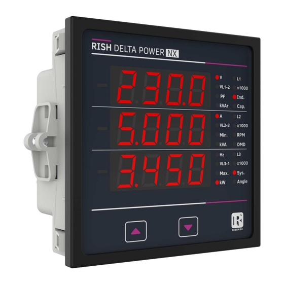
- Page 4 1. Introduction The Multifunction Meter is a panel mounted 96 x 96mm DIN Quadratic Digital Panel Meter, which measures important electrical parameters in 3P4W, 3P3W, 1P3W (Split Phase) and 1P2W networks and replaces the multiple analog panel meters. It measures electrical parameters like AC Voltage, Current, Frequency, Power Factor, Active Power, Reactive Power, Apparent Power.
- Page 5 :- UP Key scrolls through L1 Voltage, L2 Voltage, L3 Voltage, L12 Voltage, L23 Voltage, L31 Voltage, L1 Current, L2 Current, L3 Current, Neutral Current , System RPM, System Frequency, L1 Reactive Power, L1 Apparent Power, L1 Active Power, L2 Reactive Power, L2 Apparent Power, L2 Active Power, L3 Reactive Power, L3 Apparent Power, L3 Active Power, L1 Power Factor, L2 Power Factor, L3 Power Factor, L1 Phase Angle, L2 Phase Angle, L3 Phase Angle, System Reactive Power, System Apparent...
- Page 6 2. Measurement Parameters √ : Available TABLE 1: Measured Parameters x : Not Available Measured Parameter Unit 3P4W 3P3W 1P2W 1P3W System Voltage System Current Voltage L1 ...
- Page 7 Table 1 : Continued Measured Parameter Unit 3P4W 3P3W 1P2W 1P3W Phase Angle L1 Degree Phase Angle L2 Degree Phase Angle L3 Degree System RPM ...
- Page 8 Setup Parameter Screens CodE (PassWord ) Exit from setup parameter to Main Display SEL (Select) " " " " " " " " " " " " " " quit SYS PArA rESEt Ser PArA Out PArA (Exit Menu) (System Parameter) (Serial Comm.Parameter) (Reset Parameter) (Output Parameter)
- Page 9 3. Programming The following sections comprise step by step procedures for configuring the Multifunction Meter for individual user requirements. To access the set-up screens press and hold the “ ” and “ ” key simultaneously for 5 seconds. This will take the user into the password protection entry stage (section 3.1). 3.1.
- Page 10 Enter Password, fourth Pressing the “ ” key to advance the operation digit entered, awaiting to the next digit and sets the first digit, in this case to “2” verification of the password. New/Change Password, first digit entered, prompting for second digit.
- Page 11 New Password Confirmed 3.2.3 Reset Parameter Selection Screen Pressing the “ ” key will return to the “New/Change This screen is used to reset Password ”. the different parameters. Pressing the “ ” key will K r h Pressing the “ ” key allows advances to the Menu the user to reset different Selection screen (See...
-
Page 12: Potential Transformer Primary Value
Initially the “multiplier must be selected, pressing the 3.2.1 System Parameters Selection “ ” key will move the decimal point position to the 3.2.1.1 System Type right until it reaches # # #.# after which it will return to #. # # #. This screen is used to set the Pressing the “... -
Page 13: Potential Transformer Secondary Value
When the least significant digit has been set pressing If the scalling is not correct, pressing the “ ” key the “ ” key will advance to the Potential Transformer will return to the “Potential Transformer Secondary Primary Value confirmation stage. Value Edit screen. -
Page 14: Demand Integration Time
3.2.1.5 Current Transformer Secondary Value Setting 30 displays measured currents as 0 below 30 mA. This screen is used to set the value for Current Transformer 3.2.1.8 Auto Scrolling Secondary value, “5” for 5A or “1” for 1A can be selected. L3 L1 Hz P F M K W h This screen allows user to... -
Page 15: Rs 485 Baud Rate
V A h 3.2.2 Communication Parameter Selection 3.2.2.2 RS 485 Baud Rate 3.2.2.1 Address Setting This screen allows the user This screen applies to the RS 485 to set Baud Rate of RS 485 port. output only. This screen allows the The values displayed on user to set RS 485 parameter for screen are in kbaud. - Page 16 Pressing the “ ” key will Reset option “Lo” select: (Reset set the value. Min parameters). Pressing “ ” key will select the value and Pressing the “ ” key again advance to the reset all Low will jump to the Serial parameters.
- Page 17 3.2.4.1.1.1.1 Assignment of Limit Output L1 L2DM L1 L2DM 3.2.4. Output Option Selection Menu to Parameter 3.2.4.1 Configuration of Output W Ø This screen is for Limit output mode selection. It K r h W Ø This screen applies to the allows the user to set Limit output corresponding Relay Output option Selection.
-
Page 18: Trip Point Selection
3.2.4.1.1.1.3 Trip Point Selection Entered the value for third L1 L2DM digit. This screen applies to the Trip Point Selection. Press the “ ” key to advance This screen allows the user to set Trip point for K r h to next Screen the meter. -
Page 19: De-Energizing Delay Time
The second digit entered, Pressing “ ” key accepts the prompt for third digit present value and “ ” key (Blinking digit denotes advance to Configuration of that value will be output. (See section 3.2.4.1) changing).Use the “ ” key Pressing the “... -
Page 20: Number Of Interruption
. Number of Interruption 7. Negative Sign Indication If the segment glows, it indicates negative This screen displays the sign of displayed total no. of times the auxiliary parameter. supply was interrupted. Even if the auxiliary supply is When Power factor lies interrupted count will be in second and third maintained in internal memory. - Page 21 Parameter 3P4W 3P3W 1P2W 1P3W Trip Point Range 100 % Value Hi-En or Hi-DEn Lo-En or Lo-DEn VAr2 10 - 120 % 10 - 100 % VAr3 10 - 120 % 10 - 100 % ...
- Page 22 Hi Alarm Energizing Delay If Hi-Alarm Energized or Hi Alarm De-Energized option The energizing delay can be set in the range from 1 is selected then relay will get Energized or to 10 sec. De-energized,if selected parameter is greater than or De-Energizing Delay equal to trip point.
- Page 23 1) Hi alarm & Energised relay 2) Hi alarm & De-energise relay Relay Energise Relay De-energise Relay De-energise Relay Energise Input Input Trip point Trip point Hysterisis point Hysterisis point Time Time 3) Lo alarm & Energised relay 4) Lo alarm & De-energise relay Relay De-energise Relay Energise Relay Energise...
- Page 24 The each byte in RTU mode has following format: 8-bit binary, hexadecimal 0-9, A-F 2 hexadecimal characters contained in each 8-bit field of the message 4 bytes (32 bits) per parameter. Format of Data Bytes Floating point format ( to IEEE 754) Most significant byte first (Alternative least significant byte first) 2 byte Cyclical Redundancy Check (CRC) Error Checking Bytes...
- Page 25 Note : Number of registers = Number of parameters x 2 Each Query for reading the data must be restricted to 40 parameters or less. Exceeding the 40 parameter limit will cause a ModBus exception code to be returned. Query : 02(Hex) 30 (Hex) 0A (Hex) 01 (Hex) 04 (Hex)
- Page 26 Table 3 : Continued Modbus Modbus Read only parameter value 3P4W 3P3W 1P3W 1P2W 3X Add. 4X Add. 30019 40019 30021 40021 30023 40023 30025 40025 VAR1...
- Page 27 Table 3 : Continued Modbus Modbus Read only parameter value 3P4W 3P3W 1P3W 1P2W 3X Add. 4X Add. 30141 40141 System RPM 30143 40143 Impulse Rate 30145 40145 System Current Max ...
- Page 28 Table 3 : Continued Modbus 3X Modbus Read only parameter value 3P4W 3P3W 1P3W 1P2W Add. 4X Add. 31327 41327 System Min Voltage 31333 41333 Max Current L1 31335 41335 Max Current L2...
- Page 29 Table 3 : Continued Modbus Modbus Read only parameter value 3P4W 3P3W 1P3W 1P2W 3X Add. 4X Add. 31395 41395 Min System VA 31397 41397 Max PF1 31399 41399 Max PF2 ...
- Page 30 Accessing 4 X register for Reading & Start Address High : Most significant 8 bits of starting Writing address of the parameter requested. Start Address low : Least significant 8 bits of starting Each setting is held in the 4X registers. ModBus code address of the parameter requested.
- Page 31 Example : Writing System type Response: System Type System type : Start address = 1772 (Hex) (3 phase 4 wire = 3) Number of registers = 02 01 (Hex) Query:( Change System type to 3P3W = 2 ) Device Address 03 (Hex) Function Code Device Address...
- Page 32 Response: 01 (Hex) Device Address Start address high : Most significant 8 bits of starting address of Function Code 10 (Hex) the parameter requested. Start address low : Least significant 8 bits of starting address of Start Address High 17 (Hex) the parameter requested.
- Page 33 Explanation for 4 X register Address Parameters Description This address is used to set the System Type. Write one of the following value to this address. 1 =1 Phase 2 Wire 4=1 Phase 3 Wire 46003 System Type 2 = 3 Phase 3 Wire 3 = 3 Phase 4 Wire Writing any other value will return error.
- Page 34 Enables to set No. of poles of a Generator of which RPM is to be measured and to which the instrument is connected to monitor its 46039 No Of Poles parameters. setting range is 2 to 40 (multiples of 2 only) This address is used to activate or de-activatethe auto scrolling.
-
Page 35: User Assignable Modbus Registers
This address is used to set the De-Energizing delay between 1 to 46067 Limit 1 Off Delay 10 . Writing any other value will return an error. 46085 Version No. This Address shows The firmware version of device Table 5: RS 485 Set-up Code Table 6: Limit Configuration Select Baud Rate Parity... - Page 36 Table 7 : User Assignable 3X & 4X Data Registers Address Address Modbus Start Address (Hex) Assignable Register (3X) (4X) High Byte Low Byte Assignable Register 1 35201 45201 35203 45203 Assignable Register 2 Assignable Register 3 35205 45205 Assignable Register 4 35207 45207 Assignable Register 5...
- Page 37 Table 8 : User Assignable mapping register ( 4X registers) Address Modbus Start Address (Hex) Assignable Register (4X) High Byte Low Byte Map Address for Assignable Register 1 405501 Map Address for Assignable Register 2 405502 Map Address for Assignable Register 3 405503 Map Address for Assignable Register 4 405504...
- Page 38 Response : Number of register Hi : Most significant 8 bits of number of registers requested. 01 (Hex) Device Address Number of register Lo : Least significant 8 bits of number of registers requested. Function Code 10 (Hex) **Note : Two consecutive 16 bit register 15 (Hex) Start Address High represent one parameter.
-
Page 39: Phasor Diagram
User assignable mapping registers User assignable data registers ( 4X Registers Table11 ) ( 3X, 4X Registers Table 10 ) (Starting Address) (Starting Address) 0x1451 0x1450 0x157D 0x1450 Voltage 2 (0x0002) (16 bit) (16 bit) 0x1453 0x1452 0x157E 0x1452 Power Factor 1 (0x001E) (16 bit) (16 bit) 0x157F... -
Page 40: Installation
11. Installation Caution In the interest of safety and functionality this product must be installed by a qualified engineer, abiding by any local regulations. Voltages dangerous to human life are present at some of the terminal connections of this unit. Panel Ensure that all supplies are de-energised before attempting any connection or disconnection. - Page 41 11.2 Case Dimension & Panel Cut Out 11.1 EMC Installation Requirements This product has been designed to meet the 96 mm certification of the EU directives when installed to a good code of practice for EMC in industrial environments,e.g. Display 1.
-
Page 42: Earth/Ground Connections
11.5 Fusing 3P4W UNBALANCED LOAD DIGITAL METERING SYSTEM It is recommended that all voltage lines are 2 5 8 11 1 3 4 6 7 9 13 14 fitted with 1 amp HRC fuse. 11.6 Earth/Ground Connections For safety reasons, CT secondary connections should be grounded in accordance with local regulations. -
Page 43: Specification
13. Specification System 3P3W, 3P4W, 1P3W And 1P2W programmable at site Nominal Input Voltage (AC RMS) 288.68VLN (500VLL) System PT Primary Values 100 VLL to 1200 VLL programmable on site (1000 MVA maximum power) (1200 kVLL when CT Primary <= 1002 A) System PT Secondary Values 100 VLL to 500 VLL programmable on site Maximum Continuous Input Voltage... - Page 44 Reference conditions for Accuracy Reference Temperature 23 °C + 2 °C Input frequency 50 or 60Hz + 2% Input waveform Sinusoidal (distortion factor 0.005) Voltage Range 40 - 120 % of nominal value Current Range 10 - 120 (200 On request) % of nominal value Input Frequency 50/60 Hz + 2 % Power Range...
- Page 45 Safety IEC 61010-1:2017 IP for Water and Dust IEC 60529 Pollution Degree Installation Category Emission CISPR 11 Isolation High Voltage Test 3.5 kV RMS, 50Hz, 1min All Circuit vs Surface 3.5 kV RMS, 50Hz, 1min Input/AUX vs Others 3.3 kV RMS, 50Hz, 1min Relay/RS485 vs Others Input voltage vs Input Current 2.2 kV RMS, 50Hz, 1 min...
Need help?
Do you have a question about the DELTA POWER NX and is the answer not in the manual?
Questions and answers