Advertisement
Quick Links
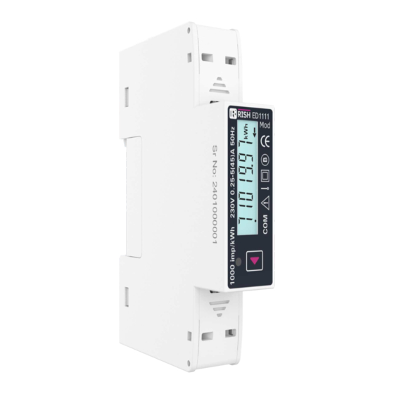
Single Phase Direct connected Energy Meter Din Mount 1U Installation Guide
The Direct Connected Energy Meter is a DIN Rail mounted Digital Meter, primarily for bidirectional
Active, Reactive and Apparent Energy measurement intended for use in industrial, commercial and
residential electrical energy metering. It also accurately measures important electrical parameters
like TRMS Voltage, TRMS Current, Frequency, Active / Reactive and Apparent Power, and Power
Factor in Single Phase Networks. The meter is engineered using advanced microcontroller techno-
logy and is suitable for electrical parameter measurement and monitoring in 1 Phase 2 Wire
Networks. It supports maximum 45 A current measurement on direct connection. It displays
parameters on bright intuitive LCD and also has Pulse Outputs and Impulse LED for energy
monitoring. It supports Tariff Counters selectable via MODBUS Communication as per model. It has
inbuilt industry standard MODBUS RTU for remote monitoring.
Safety Precautions:
All safety related codifications, symbols and instructions that appear in this operating manual or on
the equipment must be strictly followed to ensure the safety of the operating person as well as the
instrument.
If the equipment is not used in a manner specified by the manufacturer it might impair the protection
provided by the equipment.
Do not use the equipment if there is any mechanical damage.
Ensure that the equipment is supplied with correct voltage.
1. Read complete instructions prior to installation and operation of the unit.
2. Risk of electric shock.
3. The equipment in its installed state must not come in close proximity to any heating sources, oils,
steam, caustic vapors or other unwanted process by products.
4. Circuit breaker should be installed and preferably near equipment so that in case of hazards can
be accessed easily for switching off the mains.
Wiring Guidelines:
1. To prevent the risk of electric shock, power supply to the equipment must be Kept OFF while doing
the wiring arrangement.
2. Wiring shall be done strictly according to the terminal layout. Confirm that all connections are
correct.
3. Use lugged terminals.
4. To reduce electromagnetic interference use of wires with adequate ratings and twists of the same
in equal size shall be made with shortest connections.
5. Layout of connecting cables shall be away from any internal EMI source.
6. Cable used for connection to power source, must have across section of 10 mm
These wires shall have current carrying capacity of 45A.
7. Copper cable should be used (Stranded or Single core cable).
8. Before attempting work on device, ensure absence of voltages using appropriate voltage
detection device.
9.Use the wire sizes and tightening torque as listed below
2
Current input wire size 10mm
Tightening torque 0.5Nm
2
RS485/SO wire size 0.1 to 2.5 mm (Solid/Stranded with pin type lug)
Tightening torque 0.3 to 0.4 Nm.
Installation Guidelines
1. This equipment, being normally becomes a part of main control panel and in such case the
terminals do not remain accessible to the user end after installation and internal wiring.
2. Conductors must not come in contact with the internal circuitry of the equipment or else it may
lead to a safety hazard that may in turn endanger life or cause electrical shock to the operator.
3. The equipment shall not be installed in environmental condition other than those mentioned in this
manual.
4. Connector screw must be tightened after installation.
5. Enclosure is IP51 front and IP20 at terminals and to be used in indoor installations only
Dimension: 17.5 x 90 x 65 mm
FRONT
Connection Terminals Detail:
1,2
- Neutral
3
- Line In
4
- Line out
5,6
- Pulse Output
7,8
- RS485 (MODBUS)
Measurement and
Energy / Counter
Screen
Impulse LED
Multifunction
Key
SIDE
RISH ED 1111
Specifications:
Input :
Connections:
Reference Voltage (Un)
Operating Voltage Range
Power consumption in Voltage Circuit: < 2 W (10 VA)
Starting Current (Ist = 0.04*Itr)
Minimum Current (Imin = 0.5*Itr)
Transitional Current (Itr)
Communication
Reference Current (Irf = 10*Itr)
symbol
Maximum Current (Imax > 50*Itr)
Operating Current Range
Short time Over-current
Power consumption in Current Circuit
Frequency
Accuracy :
Active Energy (Import/Export)
Reactive Energy (Import/Export)
Apparent Energy
Voltage
Current
Frequency
Active Power
Reactive Power
Apparent Power
Power Factor
Pulse Outputs :
SO1
Contact Ranges
Pulse Duration
Pulse Rate
Impulse Rate
Communication Interface:
Protocol
Operating Manual
Baudrate
Data Width
Parity Stop Bits
Device Address
Response Time
TABLE 1 : Measurement Parameters:
1. Screen1
Parameter
No.
1
2
3
4
5
6
2
7
8
9
10
11
12
13
14
15
16
17
18
19
20
21
22
23
24
25
26
27
28
TABLE 1 : Measurement Parameters (contd.):
2. Screen 2
Parameter
No.
29
30
31
32
33
34
35
36
37
38
39
40
41
42
43
44
45
46
47
48
49
1 Phase 2 Wire
230 VLN
193 - 253 VLN
20 mA
250 mA
0.5 A
5 A
45 A
0.25-5 A
30*Imax for half-cycle at 50 Hz
< 1 VA per phase
45-65 Hz
Class B as per EN50470-3,
Class 1 as per IEC62053-21
Class 2 as per IEC62053-23
± 1.0 %
± 0.5% of of range max
± 0.5% of Nominal value
± 0.2% of Mid frequency
± 1% of range max
± 1% of range max
± 1% of range max
± 1% of unity
Passive Opto-isolated
5 - 27V DC, 27 mA DC (max)
60 / 100 / 200 millisecond
1 / 10 / 100 / 1000 pulse per kWh
1000 pulse per kWh
RS485 MODBUS RTU
2.4 / 4.8 / 9.6 /19.2 / 38.4 kbps
8
None -1 / None -2/ Even -1 / Odd -1
1- 247
200 millisecond (1000 millisecond for
2.4/4.8 Kbit Baudrate)
Parameters
Import Active Energy
Export Active Energy
Total Active Energy
Import Reactive Energy
Export Reactive Energy
Total Reactive Energy
Total Apparent Energy
Partial Import Active Energy
Partial Export Active Energy
Partial Total Active Energy
Partial Import Reactive Energy
Partial Export Reactive Energy
Partial Total Reactive Energy
Partial Total Apparent Energy
Voltage
Current
Active Power
Reactive Power
Apparent Power
Power Factor
Frequency
Cst - xxxx
Add - xxx
bd - xxxx
Pd - Pd count of meter
Active tariff status
Serial Number
Display Test
Parameters
T1 Import Active Energy
T1 Export Active Energy
T1 Total Active Energy
T1 Import Reactive Energy
T1 Export Reactive Energy
T1 Total Reactive Energy
T1 Total Apparent Energy
T2 Import Active Energy
T2 Export Active Energy
T2 Total Active Energy
T2 Import Reactive Energy
T2 Export Reactive Energy
T2 Total Reactive Energy
T2 Total Apparent Energy
Import W Max Demand
Export W Max Demand
Import VAr Max Demand
Export VAr Max Demand
Import VA Max Demand
Export VA Max Demand
Current Max Demand
On Display On Modbus
--
On Display
On Modbus
Advertisement

Related Manuals for Rish ED 1111


Summary of Contents for Rish ED 1111
- Page 1 RISH ED 1111 Single Phase Direct connected Energy Meter Din Mount 1U Installation Guide Specifications: Input : Connections: 1 Phase 2 Wire Reference Voltage (Un) 230 VLN Operating Voltage Range 193 - 253 VLN Power consumption in Voltage Circuit: < 2 W (10 VA) Measurement and Starting Current (Ist = 0.04*Itr)
- Page 2 Measurement Parameters Screens LCD Display Introduction The meter displays more than 40 measurement parameters including Total Energies, Tariff, Partial and also other important electrical parameters like Max Demand, Voltage, Current, Frequency, Active Power, Reactive Power, Apparent Power and Power Factor on individual screens. The user can easily scroll the Parameter By Pressing key and By Pressing and Holding key for 5 Seconds on screen 2 option the user can see Tarrif &...
Need help?
Do you have a question about the ED 1111 and is the answer not in the manual?
Questions and answers