Table of Contents
Advertisement
Quick Links
Advertisement
Table of Contents

Related Manuals for Rish ED 1100


Summary of Contents for Rish ED 1100
- Page 1 Operating Manual RISH ED 1100 DMAN-00IM-1073...
-
Page 2: Table Of Contents
Index Section Contents Introduction LCD Display 2.1 Introduction LCD Display Symbols and Indications 2.2.1 SO Output Indication 2.2.2 Communication Indication 2.2.3 Tariff Energy Indication 2.3 Setup Screens Navigation Map Programming 3.1 Password Protection 3.2 Setup Menu Selection 3.2.1 Communication Parameter Selection 3.2.1.1 Address Setting 3.2.1.2 RS 485 Baud Rate 3.2.1.3 RS 485 Parity &... - Page 3 Installation 7.1 EMC Installation Requirements 7.2 Case Dimensions 7.3 Nameplate 7.4 Wiring 7.5 Auxiliary Supply 7.6 Fusing Connection Diagrams Specification...
-
Page 4: Introduction
1. INTRODUCTION The Direct Connected Energy Meter is a DIN Rail mounted Digital Meter, primarily for bidirectional Active, Reactive and Apparent Energy measurement intended for use in industrial, commercial and residential electrical energy metering. It also accurately measures important electrical parameters like TRMS Voltage, TRMS Current, Frequency, Active / Reactive and Apparent Power, and Power Factor in Single Phase Networks. -
Page 5: Lcd Display Symbols And Indications
2. LCD Display 2.1. Introduction The meter displays more than 80 measurement parameters including Total Energies, Tariff, Partial and also other important electrical parameters like Max Demand, Voltage, Current, Frequency, Active, Power, Reactive Power, Apparent Power and Power Factor on individual screens. The user can easily scroll and See System Parameter By Pressing Scroll key and By Pressing and Holding Scroll key for 5 Seconds the user can see Tarrif &... -
Page 6: Tariff Energy Indication
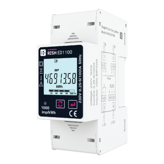
2.2.3 Tariff Energies Indication This Instrument comes with 2 tariff based on Digital Input In the image given here, it indicates that the instrument is currently displaying the selected energy parameter (Import Active Energy) of Tariff 2. These Tariff energies and Demand parameters are available on display screen 2, For opening the Screen 2 Press and hold the Scroll Key for 5 Seconds TABLE 1 : Measurement Parameters:... - Page 7 TABLE 1 : Measurement Parameters (contd.): Parameter Parameters On Display On Modbus Frequency T1 Import Active Energy T1 Export Active Energy T1 Total Active Energy T1 Import Reactive Energy T1 Export Reactive Energy ...
-
Page 8: Setup Screens Navigation Map
2.3 Setup Parameters Screens Navigation Map CodE (PassWord ) Add 001 (Modbus Address) (Sec 3.2.2.1) bd 9600 (Baud Rate) (Sec 3.2.2.2) Prtyn-1 (Parity and Stop Bits) (Sec 3.2.2.3) PLS1out (Pulse Output 1 Para Selection) (Sec 3.2.3.1.1.2) PLS2out (Pulse Output 2 Para Selection) (Sec 3.2.3.1.1.2) Cst 1000 (Pulse Rate) -
Page 9: Programming
3. PROGRAMMING The following sections comprise step by step procedures for configuring the Energy Meter according to individual user requirements. To access the set-up screens press and hold “ ”enter key for 5 seconds. This will take the User into the Password Protection Entry Stage (Section 3.1). 3.1 Password Protection Password protection can be enabled to prevent unauthorized access to set-up screens, when default password protection is not enabled. -
Page 10: Setup Menu Selection
3.2 Setup Menu selection 3.2.1 Communication Parameter Selection 3.2.1.1 Address Setting This screen applies to the RS 485 output. This screen allows the user to set RS 485 address for the meter. The allowable range of addresses is 1 to 247. Press “... -
Page 11: Output Parameter Selection
Pressing the “ ” enter key advances to the “Parity & Stop bit Edit” mode & pressing the “ ’’scroll keys scrolls the value through: nonE1: no parity with one stop bit, nonE2: no parity with two stop bit, EVEn: even parity with one stop bit, odd: odd parity with one stop Pressing enter key sets the value and advances to “output parameter Selection”... -
Page 12: Pulse Duration
3.2.2.3 Pulse Duration This screen applies only to the Pulse Output. This screen allows the user to set pulse Output energization time in milliseconds. Pressing “ ” scroll key accepts the present value and advance to “Demand integration time” screen ( see section 3.2.2.4). Pressing the “... -
Page 13: New / Change Password
3.2.2.7 New / Change Password This screen allows user to set password screen scrolling. Pressing “ ” scroll key accepts the present status and advance to the “quit screen” screen (see Section 3.2.2.8). Pressing the “ ”enter key advances to “Set password Edit” mode and pressing the “... -
Page 14: Digital Input
4. Digital Input : The meter is optionally provided with 1 Digital Inputs for selection of active tariff respectively for energy metering. 4.1 Digital Input and Tariff Selection: TABLE 2 : Relationship between Digital Input and Tariff Digital Input 1 Tariff number Tariff 1 HIGH Tariff 2... - Page 15 6. RS 485 ( ModBus ) Output : The Energy Meter supports MODBUS (RS485) RTU protocol (2-wire ) . Connection should be made using twisted pair shielded cable. All "A" and "B" connections are daisy chained together. The screens should also be connected to the “Gnd” terminal. To avoid the possibility of loop currents, an Earth connection should be made at one point on the network.
- Page 16 The function code is not supported by Meter Illegal function Attempt to access an invalid address or an Illegal Data Address attempt to read or write part of a floating point value Attempt to set a floating point variable to an invalid value Illegal DataValue 6.1 Accessing 3X and 4X register for reading measured values: Two consecutive 16 bit registers represent one parameter.
- Page 17 4X Response: Watt1 (2000 W) 01 (Hex) 03 (Hex) 04 (Hex) 44 (Hex) FA (Hex) 00 (Hex) 00 (Hex) CE (Hex) F2 (Hex) Device Function Byte Data Register1 Data Register1 Data Register2 Data Register2 Address Code Count Low Byte High Byte Low Byte High High Byte...
- Page 18 TABLE 4 : Continued Address Address Hex Address Parameter Parameter (3X) (4X) Number High Byte Low Byte 30029 40029 30031 40031 Power Factor 30033 40033 30035 40035 40037 30037 Angle 30071 40071 Freqency 30073 40073 kW Import Demand 30075 40075 kW Import Max Demand 30077 40077...
- Page 19 TABLE 4 : Continued Address Address Hex Address Parameter Parameter (3X) (4X) Number High Byte Low Byte 30131 40131 Active Energy Overflow Count 30133 40133 Active Energy 30135 40135 Reactive Energy Overflow Count 30137 40137 Reactive Energy 30139 40139 Apparent Energy Overflow Count 30141 40141 Apparent Energy...
- Page 20 TABLE 4 : Continued Address Address Hex Address Parameter Parameter (3X) (4X) Number High Byte Low Byte 30201 40201 T2 Apparent Export Energy 30203 40203 T2 Active Energy Overflow Count 30205 40205 T2 Active Energy 30207 40207 T2 Reactive Energy Overflow Count 30209 40209 T2 Reactive Energy...
- Page 21 6.2 Accessing 4 X register for Reading & Writing Settings: Each setting is held in the 4X registers. ModBus code 03 is used to read the Demand Integration Time. Refer TABLE 5 for 4X Register addresses. Example: Reading System type System type: Start address = 1772 (Hex) Number of registers = 02 Note: Number of registers = Number of Parameters x 2...
- Page 22 Example : Writing System type System type : Start address = 1772 (Hex) Number of registers = 02 Note: Number of registers = Number of Parameters x 2 Query:( Change System type to 3phase 3wire = 2 ) Byte Count : Total number of data bytes received. 01 (Hex) Device Address Data register 1 High Byte : Most significant 8 bits of Data...
- Page 23 6.3 Accessing 4 X register for Long Energy Reading & Writing : For setting Energy start count in long energy format following query format should be used for writing energy start count. First, send query (at address 1790) to unlock the parameter. Query: (Query for Unlock to enter System Active Energy Import) Byte Count : Total number of data bytes transmitted.
- Page 24 Once the Unlock query is sent, next send query for writing Energy start count. For Example: Query for writing energy start count of 999999999 for System Active Import Energy Note: Refer TABLE 2 for register address of the selected parameter. Query: (Query enter System Active Energy Import) Byte Count : Total number of data bytes received.
- Page 25 TABLE 5 : 4 X register addresses Parameter Address Default Values Parameters Register 46001 46003 Demand Integration Time 46005 46007 Measurement Mode Watt 46009 Measurement mode VAR 46011 Nominal voltage 46013 Nominal Current 46015 Nominal Frequency 46017 Reset Parameters 46019 46021 46023 Tariff Configuration...
- Page 26 TABLE 6 : 4 X register addresses Description Parameter Address Description Parameters Register 46001 46003 Demand Integration Time Demand Period represents demand time in minutes The Applicable values are ranging from 5 to 30. 46005 46007 Measurement Mode Watt This address allow to setup total energy measurement modes.
- Page 27 TABLE 6 : Continued Parameter Address Description Parameters Register 46035 Password This Address is used to set & Reset the Password Valid Range of Password can be set is 0000-9999. 1)if password lock is present & if this location is read it will return zero 2)if password lock is present &...
- Page 28 TABLE 7 : RS 485 Setup Codes Buad Rate Parity Parameter No Stop Bit 2400 NONE 2400 NONE 2400 EVEN 2400 4800 NONE 4800 NONE 4800 EVEN 4800 9600 NONE 9600 NONE 9600 EVEN 9600 19200 NONE 19200 NONE 19200 EVEN 19200 38400...
- Page 29 Table 8 : User Assignable 3X & 4X Data Registers Address Address Modbus Start Address (Hex) Assignable Register (3X) (4X) High Byte Low Byte Assignable Register 1 31025 41025 Assignable Register 2 31027 41027 Assignable Register 3 31029 41029 Assignable Register 4 31031 41031 Assignable Register 5...
- Page 30 Table 9 : User Assignable mapping register ( 4X registers) Address Modbus Start Address (Hex) Assignable Register (4X) High Byte Low Byte Map Address for Assignable Register 1 49501 Map Address for Assignable Register 2 49502 Map Address for Assignable Register 3 49503 Map Address for Assignable Register 4 49504...
- Page 31 Response : Number of register Hi : Most significant 8 bits of number of registers requested. 01 (Hex) Device Address Number of register Lo : Least significant 8 bits of number of registers requested. Function Code 10 (Hex) **Note : Two consecutive 16 bit register Start Address High 15 (Hex) represent one parameter.
- Page 32 User assignable mapping registers User assignable data registers ( 4X Registers Table11 ) ( 3X, 4X Registers Table 10 ) (Starting Address) (Starting Address) 0x1451 0x1450 0x157D 0x1450 Voltage 2 (0x0002) (16 bit) (16 bit) 0x1453 0x1452 0x157E 0x1452 Power Factor 1 (0x001E) (16 bit) (16 bit) 0x157F...
-
Page 33: Installation
7. Installation The Instrument should be mounted in a reasonably stable ambient temperature and where the operating temperature is within the range defined by the technical specification. Vibration should be kept to a minimum and the product should not be mounted where it will be subjected to excessive direct sunlight. Instrument DIN Rail Clip DIN Rail... -
Page 34: Case Dimensions
4. ESD precautions must be taken at all times when handling this product. 7.2 Case Dimensions SIDE 7.3 Name Plate... -
Page 35: Wiring
7.4 Wiring Input connections are made directly to screw-type terminals with indirect wire pressure. Numbering is clearly marked at the connector location. Choice of cable should meet local regulations. : It is recommended to use wire with lug for connection with meter. Note Wire: It is suggested to use wire with a temperature rating of at least 83 Deg. -
Page 36: Connection Diagrams
8. Connection Diagrams Connection Terminals Detail: - Neutral - Line In - Line out - SO1 Output 9,10 - SO2 Output 11,12 - DI / TARIFF SIGNAL... -
Page 37: Specification
9. Specification Input : Connections: 1 Phase 2 Wire Reference Voltage 230 VLN Operating Voltage Range : 184 - 276 VLN Power consumption in Voltage Circuit : < 2 W (10 VA) Starting Current (Ist = 0.04*Itr) 20 mA Minimum Current (Imin (0.5*Itr) 250 mA Transitional Current (Itr) 0.5 A... - Page 38 Display Ranges : Active Energy 0.01-99999.99 kWh Reactive Energy 0.01-99999.99 kVARh Apparent Energy 0.01-99999.99 kVAh Active Power 0-99999 W Reactive Power 0-99999 VAR Apparent Power 0-99999 VA Digital Input : High 20... 300 VAC / 10... 60 VDC Installation : Indoor Enclosure IP51 (IEC 60529: 1989)
Need help?
Do you have a question about the ED 1100 and is the answer not in the manual?
Questions and answers