Table of Contents

Subscribe to Our Youtube Channel
Related Manuals for Palmgren 9680157A


Summary of Contents for Palmgren 9680157A
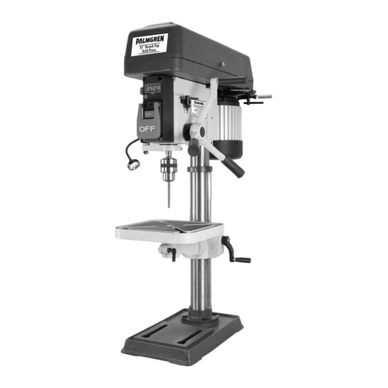
- Page 1 Operating Manual & Parts List 9680157A & 9680158A 15˝ Bench Top Drill Press & 15˝ Floor Model Drill Press Read carefully and follow all safety rules and operating instructions before first use of this product. 964847404-0823...
-
Page 2: Specifications
Remove coating with mild solvents such as mineral spirits Palmgren Drill Presses feature a heavy cast iron base, column collar, and a soft cloth. Nonflam mable solvents are recommended. After work table and head. - Page 3 Palmgren Operating Manual & Parts List 9680157A & 9680158A SAFETY RULES (CONTINUED) • Feed work into a bit or cutter against the direction of rotation of bit or cutter. WORK AREA SHOULD BE READY FOR JOB • Turn the machine off if it jams. A cutter jams when it digs too •...
-
Page 4: Installation
Palmgren Operating Manual & Parts List 9680157A & 9680158A ASSEMBLY (CONTINUED) INSTALLATION MOUNT HEAD ASSEMBLY Refer to Figure 9. MOUNT DRILL PRESS WARNING: Although compact, the drill press head assembly is • Drill press must be mounted to flat level surface. Use shims or heavy. -
Page 5: Electrical Connections
Palmgren Operating Manual & Parts List 9680157A & 9680158A INSTALLATION (CONTINUED) as viewed from shaft end of motor. • A label on the motor describes the possible wiring WARNING: This work should be performed by a qualified configurations. There are many different possible combinations, electrician. -
Page 6: Depth Stop Adjustment
Palmgren Operating Manual & Parts List 9680157A & 9680158A Belt Location A1-5Z B2-5Z A1-4Y Spindle Motor C3-5Z D4-5Z A1-3X B2-4Y A1-2W C3-4Y B2-3X 1491 E5-4Y 1660 D4-3X 1761 C3-2W 2362 D4-2W 2444 E5-3X Figure 5 – Spindle speed adjustments. 3476... -
Page 7: Maintenance
Palmgren Operating Manual & Parts List 9680157A & 9680158A OPERATION (CONTINUED) LUBRICATION Refer to Figures 7 and 8. DIGITAL DISPLAY PANEL Refer to Figure 6. The ball bearings are lubricated at the factory and need no further lubrication. Using 20wt. non-detergent oil, periodically lubricate the •... - Page 8 Palmgren Operating Manual & Parts List 9680157A & 9680158A 12 (54ZW29) 12 (9680157A) 13 (54ZW30) 13 (9680158A) 5 (54ZW30) 5 (9680158A) 6 (54ZW29) 6 (9680157A) 1 (54ZW29) 1 (9680157A) 2 (54ZW30) 2 (9680158A) Figure 7 – Replacement Parts Illustration for Base...
- Page 9 Palmgren Operating Manual & Parts List 9680157A & 9680158A REPLACEMENT PARTS LIST FOR BASE Ref. Description Part Number Qty. Base for 9680157A 963217205 Base for 9680158A 963217210 Column Holder Assembly for 9680157A 963217305 Column Holder Assembly for 9680158A 963217310 M10 × 1.5-40 Hex Head Bolt...
- Page 10 Palmgren Operating Manual & Parts List 9680157A & 9680158A e 8 - Replacement Parts Illustration for Spindle and Drive Figure 8 – Replacement Parts Illustration for Spindle & Drive...
- Page 11 Palmgren Operating Manual & Parts List 9680157A & 9680158A REPLACEMENT PARTS LIST FOR SPINDLE & DRIVE Ref. Ref. Description Part No. Qty. Description Part No. Qty. Feed Shaft Assembly 963214005 Driving Sleeve Assembly 960962405 M10 × 1.5 T=8 Hex Nut...
- Page 12 Palmgren Operating Manual & Parts List 9680157A & 9680158A 72 (9680157A) 73 (9680158A) Figure 9 – Replacement Parts Illustration for Head...
- Page 13 Palmgren Operating Manual & Parts List 9680157A & 9680158A REPLACEMENT PARTS LIST FOR HEAD Ref. Ref. Description Part No. Qty. Description Part No. Qty. Speed Sensor 964854101 M10 × 1.5 T = 8 Hex Nut Self-tapping Screw ST2.2 × 6.5...
- Page 14 Palmgren Operating Manual & Parts List 9680157A & 9680158A NOTES...
- Page 15 Palmgren Operating Manual & Parts List 9680157A & 9680158A NOTES...
- Page 16 9680157A & 9680158A PALMGREN WARRANTY C.H. Hanson / Palmgren warrants their products to be free of defects in material or workmanship. This warranty does not cover defects due directly or indirectly to misuse, abuse, normal wear and tear, failure to properly maintain the product, heated, ground or otherwise altered, or used for a purpose other than that for which is was intended.
Need help?
Do you have a question about the 9680157A and is the answer not in the manual?
Questions and answers