
Subscribe to Our Youtube Channel
Related Manuals for Palmgren 9680130


Summary of Contents for Palmgren 9680130
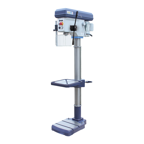
- Page 1 9680130 operating manual & parts list 16'' Drill press W/PF Read carefully and follow all safety rules and operating instructions before first use of this product.
-
Page 2: Table Of Contents
1.16 Accident report ............................13 1.17 Electronics .............................13 Inspection deadlines..........................13 1.18 Technical specification Emissions ..............................14 Dimensions DH28FS(9680130 ) ......................16 Assembly Scope of delivery ...........................18 Transport ...............................18 Set-up and assembly ..........................18 3.3.1 Installation site requirements......................19 Installation..............................19 3.4.1 Fixing............................19 First commissioning ..........................20 3.5.1 Electrical connection ........................20... - Page 3 Operation Control and indicating elements ......................22 4.1.1 Drilling machine DH28FT - DH28FS(9680130) ................. 22 4.1.2 Control panel ..........................23 Safety..............................23 Switching on the machine........................24 Switching off the machine........................24 Speed variation............................24 4.5.1 Speed table ..........................24 Drill depth stop............................25 Automatic spindle sleeve feed ........................25 Disassembly, assembly of drill chucks and drill bits ................
- Page 4 8.2.2 Säule und Bohrtisch - Column and drilling table ................. 38 Ersatzteilliste - Parts list ......................... 39 Bohrfutterschutz - Drill chuck protection....................43 Schaltplan - Wiring diagram DH28FT/DH28FS ( 9 6 8 0 1 3 0 ) ..............44...
-
Page 5: Safety
Safety Glossary of symbols provides further instructions calls on you to act listings This part of the operating instructions explains the meaning and use of the warning notes included in these operating instructions, defines the intended use of the drilling machine, ... -
Page 6: Safety Instructions (Warning Notes)
Safety instructions (warning notes) 1.2.1 Classification of hazards We classify the safety warnings into different categories. The table below gives an overview of the classification of symbols (ideogram) and the warning signs for each specific danger and its (possible) consequences. Symbol Alarm expression Definition / consequence... -
Page 7: Intended Use
Switching on forbidden! Pull out the mains plug! Read the operating instruc- Do not climb onto the tions before commission- machine! ing! Wear protective glasses! Wear protective gloves! Wear safety shoes! Wear a protective suit! Use ear protection! Only switch during stand- Protect the environment! Contact address still! -
Page 8: Reasonably Foreseeable Misuse
Reasonably foreseeable misuse Any use other than that specified under "Intended use" or any use beyond that described will be deemed non-intended use and is not permissible. Any other use has to be discussed with the manufacturer. It is only allowed to process metal, cold and non-inflammable materials with the drilling machine. -
Page 9: Qualification
If the drilling machine is used and maintained by personnel who are not duly qualified, there may be a risk resulting from incorrect or unsuitable maintenance of the geared drill. INFORMATION Everyone involved in the assembly, commissioning, operation and maintenance must be duly qualified, ... -
Page 10: User Positions
User positions The operator position is in front of the drilling machine. Safety measures during operation CAUTION! Danger due to inhaling dust and mist that is hazardous to health. Dependent on the material which need to be processed and the used auxiliaries dusts and mist may be caused which might impair you health. -
Page 11: Safety Check
1.10 Safety check Check the drilling machine before each start-up or at least once per shift. Inform the person responsible immediately of any damage, defects or changes in the operating function. Check all safety devices at the beginning of each shift (with the machine stopped), ... -
Page 12: 1.11.2 Drill Chuck Guard
Emergency-stop Master switch Img.1-1: Master switch 1.11.2 Drill chuck guard Adjust the guard to the correct height before you start working. To do so, slacken the clamping screw, set the required height and re-tighten the clamping screw. There is a switch integrated in the spindle protection mounting which monitors the closed posi- tion. -
Page 13: Safety During Operation
1.13 Safety during operation We provide information about the specific dangers when working with and on the drilling machine in the descriptions for these types of work. WARNING! Before switching on the drilling machine make sure that there are no dangers generated for persons, ... -
Page 14: Accident Report
grounding cables. Check if they are working properly! 1.16 Accident report Inform your supervisors and Optimum Maschinen Germany GmbH immediately in the event of accidents, possible sources of danger and any actions which almost led to an accident (near misses). -
Page 15: Technical Specification
Technical specification The following information represents the dimensions and indications of weight and the manu- facturer‘s approved machine data. Electrical connection DH28FS/9680130 115V ~60 Hz 1PH Connection Drilling capacity Drilling capacity in steel [mm]/inch 28/1.1'' Throat [mm] 200/7.87'' Spindle sleeve stroke [mm] 105/4.13''... - Page 16 INFORMATION This numerical value was measured on a new machine under the operating conditions specified by the manufacturer. The noise behaviour of the machine might change depending on the age and wear of the machine. Furthermore, the noise emission also depends on production engineering factors, e.g. speed, material and clamping conditions.
- Page 17 Schwerpunkt/Centre of gravity Img.2-1: Dimensions DH28FT...
-
Page 18: Dimensions Dh28Fs(9680130 )
Dimensions DH28FS Schwerpunkt/Centre of gravity Img.2-2: Dimensions DH28FS... -
Page 19: Assembly 3.1 Scope Of Delivery
Assembly Scope of delivery When the machine is delivered, please check immediately that it has not been damaged during transport. Compare the scope of delivery with the attached packing list. Transport Centres of gravity Load suspension points (Marking of the positions for the load suspension gear) Prescribed transport position ... -
Page 20: Set-Up And Assembly
Set-up and assembly 3.3.1 Installation site requirements Organize the working area around the drilling machine according to the local safety regulations. INFORMATION In order to attain good functionality and a high processing accuracy as well as a long service life of the machine, the place of installation should fulfil certain criteria. -
Page 21: First Commissioning
ATTENTION! Tighten the fixing screws of the drilling machine only as much that it is safely fixed and cannot break away or tilt over. If the fixing screws are too tight in particular in connection with an uneven substructure it may result in a broken stand of the machine. -
Page 22: Warming Up The Machine
3.5.2 Warming up the machine ATTENTION! If the drilling machine and in particular the drilling spindle is immediately operated at maximum load when it is cold it may result in damages. If the machine is cold, e.g. directly after having transported the machine, it should be warmed up at a spindle speed of only 500 1/min for the first 30 minutes. -
Page 23: Operation
Operation Control and indicating elements 4.1.1 Drilling machine DH28FT - DH28FS(9680130) Img.4-1: DH28FT Pos. Designation Pos. Designation Belt drive with housing Lever for spindle sleeve feed Emergency-stop Automatic quill feed activation Drill chuck On , Off Table height adjustment Drilling table... -
Page 24: Control Panel
4.1.2 Control panel Machine illumination ON / OFF Fuses, fine-wire fuses Emergency-stop pushbutton Selector switch rotational direction Left hand motion/ clockwise Push button "ON" rotation Clamping lever Drill depth stop Push button "OFF" Img.4-2: Operating elements on the control panel Safety Commission the machine only under the following conditions: The machine is in proper working order. -
Page 25: Switching On The Machine
Switching on the machine Switch on the master switch. Select the direction of rotation. Actuate the push button "ON". Switching off the machine CAUTION! Only press the emergency stop button in a genuine emergency. You should not use the emergency-stop button to stop the machine during normal operation. -
Page 26: Drill Depth Stop
Drill depth stop Use the drilling depth stop when drilling several holes of the same depth. Loosen the locking screw and turn the graduated collar until the required drilling depth matches with the indicator. Re-tighten the locking screw. Automatic spindle sleeve feed The drilling depth stop is adjustable in the range of 0-95 mm. -
Page 27: Before Starting Work
4.10 Before starting work Before starting work, select the desired speed. It is depending on the used drilling diameter and on the material. WARNING! For drilling jobs, it is necessary to clamp the workpiece firmly to prevent the bit catching on the pieces. -
Page 28: Maintenance
Maintenance In this chapter you will find important information about Inspection, Maintenance and Repair. ATTENTION! Properly performed regular maintenance is an essential prerequisite for operational safety, failure-free operation, long service life of the machine and ... - Page 29 Interval Where? What? How? Examination for outside damages. Start of shift "Safety check“ on page 48 After each maintenance or repair work Lubricate the drill column regularly with commercial oil, machine oil, engine oil. Lubricate the toothed rod regularly with commercial grease (e.g.
-
Page 30: Repair
Repair 5.3.1 Customer service technician For any repair work request the assistance of an authorised customer service technician. Con- tact your specialist dealer if you do not have customer service's information or contact Stürmer Maschinen GmbH in Germany who can provide you with a specialist dealer's contact informa- tion. -
Page 31: Malfunctions
Malfunctions Cause/ Malfunction Solution possible effects Motor is hot • Wrong electrical connection of 400V • "Electrical connection“ on page machines Noise during work. • Spindle is too little lubricated • Lubricate spindle (only possible • Tool is blunt or wrongly clamped when disassembled) •... -
Page 32: Appendix 7.1 Copyright
Appendix Copyright This document is protected by copyright. All derived rights are reserved, especially those of translation, re-printing, use of figures, broadcast, reproduction by photo-mechanical or similar means and recording in data processing systems, either partial or total. Subject to technical changes without notice. Terminology/Glossary Term Explanation... -
Page 33: Advice For Disposal / Options Of Reuse
Advice for disposal / Options of reuse: Please dispose of your equipment in an environmentally friendly manner, by not placing waste in the environment but in a professional manner. Please do not simply throw away the packaging and later the disused machine, but dispose of both in accordance with the guidelines laid down by your city council/local authority or by an authorised disposal company. -
Page 34: Disposal Of Electrical And Electronic Components
separately and professionally. In case of doubt, please contact your municipal waste manage- ment. If appropriate, call on the help of a specialist waste disposal company for the treatment of the material. 7.4.4 Disposal of electrical and electronic components Please make sure that the electrical components are disposed of professionally and according to the statutory provisions. - Page 35 Fragile goods (Goods require careful handling) Protect against moisture and humid environment Prescribed position of the packing case (Marking the top surface - arrows pointing up) Maximum stacking height Example: not stackable - do not stack a second pack- ing case on top of the first one.
-
Page 36: Ersatzteile - Spare Parts
Ersatzteile - Spare parts Bohrkopf - Drilling head 8-1: Bohrkopf - Drilling head... -
Page 37: Pinolenvorschub - Spindle Sleeve Feed
Pinolenvorschub - Spindle sleeve feed 8-2: Pinolenvorschub - Spindle sleeve feed... -
Page 38: Keilriemenantrieb - V-Belt Drive
8.2.1 Keilriemenantrieb - V-belt drive 29-1 97-1 31-1 36-2 36-3 36-4 36-5 34-1 36-1 29-1 8-3: Keilriemenantrieb - V-belt drive... - Page 39 8.2.2 Säule und Bohrtisch - Column and drilling table 100-1 75-1 71-1 19-1 20-1 83-1 15-1 15-1 10-2 10-1 8-4: Säule und Bohrtisch DH28FS- Column and drilling table DH28FS...
- Page 40 Ersatzteilliste - Parts list DH28FT - DH28FS Menge Grösse Artikelnummer Pos. Bezeichnung Designation Qty. Size Item no. Standfuss Base 030202841 Säule Column DH28FS 0302028402 Säule Column DH28FT 0302026002 Zahnstange Toothed rack 030202843 Zahnrad Toothed wheel 030202414 Antriebsschnecke Drive screw 030202415 Spindel Spindle 030202847...
- Page 41 34-1 Paßfeder Feather key Platte Schließer Plate closer Innensechskantschraube Socket head screw M6x15 36-1 Scheibe Washer 36-2 Innensechskantschraube Socket head screw 36-3 Scharnier Articulation 36-4 Scheibe Washer 36-5 Sechskantmutter Hexagonal nut Spindelmutter Spindle nut 0302028437 37-1 Kugellager Ball bearing 6004-2Z 0406004ZZ 37-2 Innensechskantschraube...
- Page 42 Distanzscheibe Distance plate 0302024183 Innensechskant - 83-1 Threaded pin M6x6 Stiftschraube Sechskantmutter Hexagon nut Kugel Ball Ø6mm 042KU06 Feder Feather 0302028493 Gewindestift Setscrew M6x20 Auswerfer Eejector 0302028495 Sicherungsring Circlip 97-1 Sicherungsring Circlip Lager Bearing 6203 0406203R Ring Ring 0302028499 Gewindestift Setscrew M8x15 100-1...
- Page 43 Riemenscheibe Pulley 03020284148 Nadellager Needle bearing Sicherungsring Retaining ring 042SR42W Kugellager Ball bearing 61806 04061806 Welle Shaft 03020284152 Kugellager Ball bearing 6004 0406004 Sicherungsring Retaining ring 042SR15W Zahnrad Gear 03020284155 Kugellager Ball bearing 6002 0406002R Welle Shaft 03020284157 Passfeder Fitting key 5x5x14 042P5516 Passfeder...
- Page 44 Sechskantmutter Hexagon nut Gewindestift Grub screw M6x12 Zylinderstift Cylindrical pin 4x12 Schraube Screw M6x12 Schraube Screw Schraube Screw M5x16 Scheibe Washer 03020284191 Schraube Screw M6x12 Transformator (ohne Transformer (without 0302024196 Abbildung) illustration) Contactor (without Schütz (ohne Abbildung) 230V 16A 0460025 illustration) Bohrfutterschutz - Drill chuck protection Bohrfutterschutz - Drill chuck protection...
- Page 46 Index Abmessungen ............. 20 Obligations Accident report ............ 51 user ..............46 Anschluss Operating material ..........52 elektrisch ............18 Operation .............60 Assembly ............56 Aufstellen ............23 Personal protective equipment ......49 Pflichten Bedien- und Anzeigeelemente ......26 Bediener ............11 Bedienung ............26 Pictograms ............43 Bestimmungsgemäße Verwendung ......
Need help?
Do you have a question about the 9680130 and is the answer not in the manual?
Questions and answers